NTI ENVIROMUX Series Installation And Operation Manual
Remote power reboot switch with iec320 c13 outlet
Hide thumbs
Also See for ENVIROMUX Series:
- Installation and operation manual (150 pages) ,
- Manual (59 pages) ,
- Instruction manual (19 pages)

Related Manuals for NTI ENVIROMUX Series


Summary of Contents for NTI ENVIROMUX Series
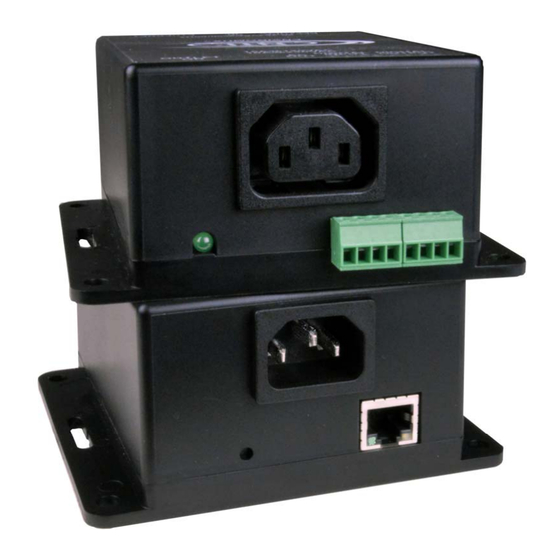
- Page 1 ® ENVIROMUX Series PWR-RMT-RBT-C13 Remote Power Reboot Switch with IEC320 C13 Outlet Installation and Operation Manual PWR-RMT-RBT-C13 (Front and Rear View) MAN436 Rev Date 9/11/2023...
- Page 2 TRADEMARK ENVIROMUX and the NTI logo are registered trademarks of Network Technologies Inc in the U.S. and other countries. All other brand names and trademarks or registered trademarks are the property of their respective owners. COPYRIGHT Copyright © 2023 by Network Technologies Inc. All rights reserved. No part of this publication may be reproduced, stored in a retrieval system, or transmitted, in any form or by any means, electronic, mechanical, photocopying, recording, or otherwise, without the prior written consent of Network Technologies Inc, 1275 Danner Drive, Aurora, Ohio 44202.
-
Page 3: Table Of Contents
TABLE OF CONTENTS Introduction..................................1 Supported Web Browsers ............................... 2 Materials ..................................2 Connectors and LEDs ..............................3 Installation ..................................4 DIN Clip Installation ..............................6 Device Discovery Tool..............................7 How to Use the Device Discovery Tool ........................7 Operation Via Web Interface ............................8 Log In and Enter Password ............................ - Page 4 Figure 15- Status of Trigger Sources ............................... 14 Figure 16- Administration Page Settings............................15 Figure 17- Network Settings page ..............................16 Figure 18- Outputs page as viewed by the User..........................19 Figure 19- Trigger Sources page as viewed by the User ......................... 19 Figure 20- Pop-up for switching to manual trigger ...........................
-
Page 5: Introduction
NTI Power Remote Rebooter with C13 Connection INTRODUCTION The ENVIROMUX® Remote Power Reboot Switch is used to remotely reboot and control power (ON/OFF) to a server or other powered device over IP. Two operating modes for power reboot: Manual – select the outlet and turn the power on/off/cycle. -
Page 6: Supported Web Browsers
CAT5/5e/6/6a/7 (CATx) unshielded twisted-pair cable(s) terminated with RJ45 connectors wired straight thru- pin 1 to pin 1, etc. for Ethernet connection Contact your nearest NTI distributor or NTI directly for all of your cable needs at 800-RGB-TECH (800-742-8324) in US & Canada or 330-562-7070 (Worldwide) or at our website at http://www.networktechinc.com... -
Page 7: Connectors And Leds
NTI Power Remote Rebooter with C13 Connection CONNECTORS AND LEDS LABEL CONNECTOR/LED DESCRIPTION RESTORE DEFAULTS Button For manually resetting the PWR-RMT-RBT-C13 to default settings- press and hold for 5 seconds to activate IEC 320 C14 Plug For connecting a line service cord... -
Page 8: Installation
3. Connect the "ETHERNET" port to your LAN with a CAT5,5e/6/6a/7 cable. This cable can be up to 328 feet in length. 4. Connect the AC OUT receptacle to a 120VAC (maximum 15A) or 240VAC (maximum 10A) device to be controlled using a suitable cable (see page 2 for cables offered by NTI). Figure 2- Connect AC OUT cable... -
Page 9: Figure 3- Connect Digital Input Sensors
NTI Power Remote Rebooter with C13 Connection 5. Connect the DIGITAL IN terminals to sensors that will act as triggers to power the PWR-RMT-RBT-C13 On and OFF. Dry contact sensors can be connected to the PWR-RMT-RBT-C13 using 26-16AWG wire. Up to 2 sensors can be connected. -
Page 10: Din Clip Installation
NTI Power Remote Rebooter with C13 Connection DIN Clip Installation If you purchased the DIN clip option for your PWR-RMT-RBT-C13 (PWR-RMT-RBT-C13-D), the clips can be attached using the hardware provided. Pass the screw through the flat washer, then through a hole in the mounting flange, and screw it tightly into the threaded hole in the clip. -
Page 11: Device Discovery Tool
Tip: If your Windows program asks which program to open the NTIDiscover.jar file with, select the Java program. Figure 7- Device Discovery Tool Click on the “Detect NTI Devices” button to start the discovery process. After a short time, the tool will display all NTI devices on your network, along with their network settings. -
Page 12: Operation Via Web Interface
Discovery Tool to identify the IP address to enter when logging in to the PWR-RMT-RBT-C13. Note: The computer using the Device Discovery Tool and the NTI Device must be connected to the same subnet in order for the Device Discovery Tool to work. If no devices are found, the message “No Devices Found” will be displayed. -
Page 13: Figure 9- Initial Screen- Outputs State
NTI Power Remote Rebooter with C13 Connection With a successful log in, the “Outputs” page with a menu at left will appear on the screen: Figure 9- Initial screen- Outputs state From this initial page, the administrator can use the menu to the left to manage all the functions of the PWR-RMT-RBT-C13. -
Page 14: Figure 10- Outputs Page With Trigger Type Set To Auto
NTI Power Remote Rebooter with C13 Connection With Trigger Type set to Auto, Trigger Sources and their status are shown Triggers that are not checked (next page) are not listed When Triggers are checked but the Trigger Type is "Manual", Triggers are listed... -
Page 15: Outputs
NTI Power Remote Rebooter with C13 Connection Outputs Figure 11- Output Control Settings Output Control Settings Description Name Enter the name you would like to be applied to the output Output Control Choose whether you want the output to be controlled manually, or automatically by configured trigger... -
Page 16: Figure 12- Set Digital Input Sensors Specified Time Period Before Causing A Trigger
NTI Power Remote Rebooter with C13 Connection Digital Input sensors need to be in a new state for a specified amount of time before a trigger can occur. Click "Edit" to open Sensor Settings page. Figure 12- Set Digital Input sensors specified time period before causing a trigger You can enter a custom description for the sensor connected to Digital In #1 and #2. -
Page 17: Figure 14- Configure Timer Settings
NTI Power Remote Rebooter with C13 Connection IP Device Settings Description (continued) Retries Enter the number of times an IP address should be pinged before it is considered unresponsive Unresponsive Action Choose whether the Trigger will be Latching (continuous) or Cycling (active for the configured cycle duration) A Latching trigger will remain triggered until IP device state changes. -
Page 18: Trigger Sources
NTI Power Remote Rebooter with C13 Connection Trigger Sources On this page you can see the status of each trigger, and if you click "Edit" you will have access to Sensor Settings (Figure 12), IP Device Settings (Figure 13) and Timer Settings (Figure 14). -
Page 19: Administration Pages
NTI Power Remote Rebooter with C13 Connection Administration Pages See page 20 for further explanation of this feature. Default Username: root Default Password: nti (all lower case characters) Figure 16- Administration Page Settings The System Settings section includes the serial number, MAC address, firmware version, web page version, unit name that the user assigns, and a check box to disable the pop-up warning messages (enabled by default- see page 20). -
Page 20: Figure 17- Network Settings Page
NTI Power Remote Rebooter with C13 Connection Under Administration you will find the Network Settings page. Figure 17- Network Settings page Network Settings Description Enable DHCP Place a checkmark to allow a DHCP server to assign the IP address and other network settings, otherwise static network settings will be as assigned below manually. - Page 21 Select whether the time should be shown in AM/PM or 24 Hour NTP Server Apply the IP address or URL of your preferred NTI server NTP Frequency Enter the frequency, in minutes, at which to query the NTP server (range is 5-1440) Note: This rebooter always needs to have a valid NTP server.
-
Page 22: Support Page
NTI Power Remote Rebooter with C13 Connection Support Page The Support Page provides a link for downloading a copy of the current product manual. Logout Page Click "Logout" to completely logout of the PWR-RMT-RBT-C13. Note: If you quickly decide you want to log back in, be sure to change the URL to just the IP address of the PWR-RMT-RBT-C13. -
Page 23: User Access
NTI Power Remote Rebooter with C13 Connection User Access The "User" access is very limited, as compared to the "Administrator" access. The "User" can view the status of Ouputs and Trigger Sources, but cannot change any device settings The "User" can still change the state of the device and change between manual and auto Trigger Type. -
Page 24: Pop-Up Messages
NTI Power Remote Rebooter with C13 Connection Pop-Up Messages Under Administration Pages, System Settings, you have the option to disable pop-up messages. These messages will remind you of the consequences of certain actions you might take in the course of controlling the behavior of the Rebooter. -
Page 25: Figure 21- Pop-Up For Changing Trigger Type
NTI Power Remote Rebooter with C13 Connection Figure 21- Pop-up for changing trigger type When in Output Control Settings, if you change the Logical Function of the IP Device Auto Trigger Settings from "OR" to "AND", a pop-up message will warn you that the trigger cycle behavior may be masked by the output logic setting. -
Page 26: Figure 23- Disable Pop-Ups On System Settings Page
NTI Power Remote Rebooter with C13 Connection These pop-up messages can be disabled by clicking the box under Administration Pages, System Settings, Place a checkmark here to disable the pop-up warning messages. Figure 23- Disable pop-ups on System Settings page... -
Page 27: Firmware Upgrade
NTI Power Remote Rebooter with C13 Connection FIRMWARE UPGRADE The PWR-RMT-RBT-C13 may, at times, have changes made to its firmware. These changes can easily be applied after installation. There are two files that make up the PWR-RMT-RBT-C13 programming, a Firmware file, and a Webpage file. The release notes that accompany the files when you download them from our webpage will describe what has changed. - Page 28 NTI Power Remote Rebooter with C13 Connection Click on "Rebooter Main Page" to take you to the webpage.
- Page 29 NTI Power Remote Rebooter with C13 Connection If the file you try to upload is the wrong kind of file, the following error message will be displayed: Wrong file If the file you try to upload has been corrupted and will no longer work in the Rebooter, the following error message will be...
-
Page 30: Http Rest Api
NTI Power Remote Rebooter with C13 Connection HTTP REST API You can use HTTP REST API to read and control status of Rebooter outputs. There are 3 API’s total: 2 to get the AC output and Digital Output status and 1 to change the state of the AC Output or Digital Outputs. - Page 31 NTI Power Remote Rebooter with C13 Connection 2. API to get AC Output and Digital Output names and current operation mode Request Type: GET Endpoint: /output.json HTTP Auth required Response Format: JSON Response contains AC Output and Digital Output names and mode in arrays in “outdata”. Trigger names can be found in “trigname”.
- Page 32 NTI Power Remote Rebooter with C13 Connection 3. API to change AC Output or Digital Output status or their Operation Mode Request Type: GET Endpoint: /updateOut.html HTTP Auth required Response Format: JSON Required parameters: “oid” is the index of Outputs ranging from 0 to 2 ...
-
Page 33: Technical Specifications
NTI Power Remote Rebooter with C13 Connection TECHNICAL SPECIFICATIONS Power 90 to 264 VAC at 50 or 60 Hz Power Switching up to 15 Amps at 105-125 VAC, 10 Amps at 210-240 VAC. Power Consumption 1.4W Input connector One IEC 320 C14 plug... -
Page 34: Catx Cable
NTI Power Remote Rebooter with C13 Connection CATx Cable The CATx connection cable (CAT5/5e/6/6a/7) between the LAN and the PWR-RMT-RBT-C13 must be terminated with RJ45 connectors and must be wired according to the EIA/TIA 568 B industry standard. Wiring is as per the table and drawing below.
Need help?
Do you have a question about the ENVIROMUX Series and is the answer not in the manual?
Questions and answers