NTI Enviromux Series Installation Manual
Digital input/output expander
Hide thumbs
Also See for Enviromux Series:
- Installation and operation manual (150 pages) ,
- Manual (59 pages) ,
- Instruction manual (19 pages)
Advertisement
Quick Links
ENVIROMUX
ENVIROMUX-DI16DO(R)16
Digital Input/Output Expander
Installation Manual
The ENVIROMUX-DI16DO(R)16 Digital Input/Output Expander enables the connection of up to 16 additional digital sensors and
output devices using just one RJ45 Sensor port on an ENVIROMUX-2D, ENVIROMUX-5D, or ENVIROMUX-16D Server
Environment Monitoring System (SYSTEM).
The ENVIROMUX-DI16DO16 includes digital outputs with an open-collector design for the control of up to 16 relays, solenoids,
LEDs, and other devices that operate at voltages between 0-24VDC (maximum 500mA).
The ENVIROMUX-DI16DOR16 includes digital outputs with a normally-open SPST relay design for the control of up to 16 different
devices that operate at a maximum125VAC (0.5A maximum) or maximum 30VDC (1.0A maximum).
Features
The ENVIROMUX-DI16DO16 and ENVIROMUX-DI16DOR16 have many features in common, and several differences, detailed
below:
Features in common:
•
Interfaces with the SYSTEM via the RJ45 Sensor Port
•
Digital inputs:
16 screw terminal pairs for connecting dry contact devices
o
One screw terminal pair for tachometer; 0 to 255 Hz
Accepts 26 to 16AWG wire
o
o
Potential free
Voltage range: 0 to +36VDC
o
o
Over-voltage surge protected
•
Supports 18-24AWG CAT5/5e/6 cable up to 500 ft. (152.4 m)
Feature differences:
Feature
ENVIROMUX-DI16DO16
•
Digital outputs
•
•
•
•
•
Power supply
Requires 75mA at 5VDC (Powered by
SYSTEM)
Dimensions (WxDxH)
6.49x3.10x1.08 in (165x79x27 mm)
®
Series
16 screw terminal pairs for open-
collector outputs
Accepts 26 to 16AWG wire
Rated sink current: 500mA per output
+5VDC, 22kΩ pull-ups
Voltage range: 0 to +24VDC
Over-voltage surge protected
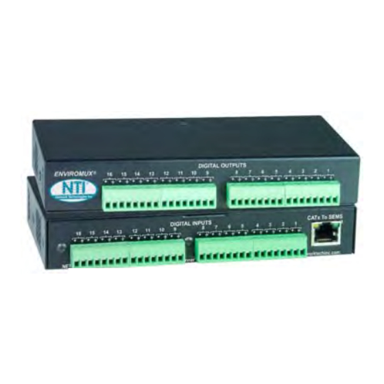
ENVIROMUX-DI16DO16 (Front and Rear View)
ENVIROMUX-DI16DOR16 (Rear View)
ENVIROMUX-DI16DOR16
• 16 screw terminal pairs for normally-open relay
contact outputs
• Accepts 26 to 16AWG wire
• Potential free
• Rated switching load: 0.5A @ 125 VAC, 1.0A @
±30VDC
• Fused
Includes 120VAC or 240VAC at 50 or 60Hz-5VDC/3.0A
AC Adapter
6.49x3.10x1.78 in (165x79x45 mm)
1
Advertisement

Related Manuals for NTI Enviromux Series


Summary of Contents for NTI Enviromux Series
- Page 1 ® ENVIROMUX Series ENVIROMUX-DI16DO16 (Front and Rear View) ENVIROMUX-DI16DO(R)16 Digital Input/Output Expander Installation Manual ENVIROMUX-DI16DOR16 (Rear View) The ENVIROMUX-DI16DO(R)16 Digital Input/Output Expander enables the connection of up to 16 additional digital sensors and output devices using just one RJ45 Sensor port on an ENVIROMUX-2D, ENVIROMUX-5D, or ENVIROMUX-16D Server Environment Monitoring System (SYSTEM).
-
Page 2: Installation
Installation 1. Connect the Expander to the SYSTEM using up to 500 feet (152.4 m) of 18-24AWG CAT5, 5e, or 6 cable. 2. Dry contact sensors can then be connected to the Expander using 26-16AWG wire. Up to 16 sensors can be connected. - Page 3 3a. Digital Outputs on the ENVIROMUX-DI16DO16 have an open-collector design for the control of up to 16 relays, solenoids, LEDs, and other devices that operate at voltages between 0-24VDC (maximum 500mA). Devices connected to Digital Outputs will display in the “Remote Output Relay” list in the SYSTEM web interface for assignment to sensor alert responses. 3b.
- Page 4 Web Interface- Summary Page The Summary Page of the SYSTEM will display sensors connected to the ENVIROMUX-DI16DO(R)16 in a separate list labeled “Remote Digital Inputs”. (The image below demonstrates the summary page with two ENVIROMUX-DI16DO16 Digital Expanders connected.) The SYSTEM will also recognize the number 1 connector set on the ENVIROMUX-DI16DO(R)16 as a possible tachometer connector, displaying its status under “Sensors”.
- Page 5 When configuring the Remote Digital Inputs for connection to a water sensors or dry-contact sensors, configure them just as you would any other Digital Input as described in the manual for the SYSTEM. When configuring the use of Remote Output Relays, configure them also as described for Output Relays in the manual for the SYSTEM.
- Page 6 SNMP Custom Type ID: Use this field if SNMP traps will be used for alert notifications. The Type ID corresponds with a value defined in the MIB file under “extSensorType” (default value is 32567 for type “Custom”). Place the desired number in this box that represents the type of sensor to be reported in the MIB browser or SNMP trap.
- Page 7 Check this box if you enter data in the next 5 boxes 255Hz (cycles) x 2.5MPH per rotation in 1 second (cycle) Configuration of tachometer as a wind speed sensor (ENVIROMUX-WSS)
-
Page 8: Cat5 Cable
CAT5 Cable The CAT5 connection cable between the SYSTEM and the ENVIROMUX-DI16DO(R)16 is terminated with RJ45 connectors and must be wired according to the EIA/TIA 568 B industry standard. Wiring is as per the table and drawing below. Pair 3 Wire Color Pair White/Orange...
Need help?
Do you have a question about the Enviromux Series and is the answer not in the manual?
Questions and answers