NTI ENVIROMUX Series Installation Manual
Digital input/output expander
Hide thumbs
Also See for ENVIROMUX Series:
- Installation and operation manual (150 pages) ,
- Manual (59 pages) ,
- Instruction manual (19 pages)
Advertisement
Quick Links
ENVIROMUX
E-DI16DO16
E-DI16DOR16-V2
Digital Input/Output Expander
Installation Manual
The E-DI16DO(R)16 Digital Input/Output Expander enables the connection of up to 16 additional digital sensors and output
devices using just one RJ45 Sensor port on an E-2D, E-5D, or E-16D Server Environment Monitoring System (SYSTEM).
The E-DI16DO16 includes digital outputs with an open-collector design for the control of up to 16 relays, solenoids, LEDs, and
other devices that operate at voltages between 0-24VDC (maximum 500mA).
The E-DI16DOR16-xx includes digital outputs with a normally-open SPST relay design for the control of up to 16 different devices
that operate at a maximum125VAC (0.5A maximum) or maximum 30VDC (1.0A maximum).
Features
The E-DI16DO16 and E-DI16DOR16-xx have many features in common, and several differences, detailed below:
Features in common:
Interfaces with the SYSTEM via the RJ45 Sensor Port
Digital inputs:
o
16 screw terminal pairs for connecting dry contact devices
One screw terminal pair for tachometer; 0 to 255 Hz
o
Accepts 26 to 16AWG wire
o
Potential free
o
Voltage range: 0 to +36VDC
o
Over-voltage surge protected
Supports 18-24AWG CAT5/5e/6 cable up to 500 ft. (152.4 m)
Feature differences:
Feature
E-DI16DO16
Digital outputs
Requires 75mA at 5VDC (Powered by
Power supply
SYSTEM)
Dimensions (WxDxH)
6.49x3.10x1.08 in (165x79x27 mm)
Note: No external earth ground connection is necessary.
Options:
E-DI16DOR16 with Standard desktop case- (Order E-DI16DOR16-V2)
E-DI16DOR16 with Rackmounting Brackets- (Order E-DI16DOR16-V2R)
Dual E-DI16DOR16 with Rackmounting Brackets (Order E-DI16DOR16-V22R)
®
Series
16 screw terminal pairs for open-
collector outputs
Accepts 26 to 16AWG wire
Rated sink current: 500mA per output
+5VDC, 22kΩ pull-ups
Voltage range: 0 to +24VDC
Over-voltage surge protected
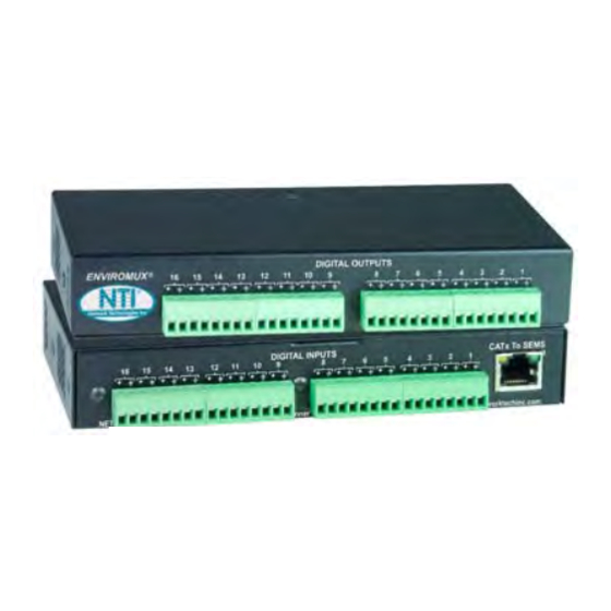
E-DI16DO16 (Front and Rear View)
E-DI16DOR16-V2 (Rear View)
E-DI16DOR16-xx
16 screw terminal pairs for normally-open relay
contact outputs
Accepts 26 to 16AWG wire
Potential free
Rated switching load: 0.5A @ 125 VAC, 1.0A @
±30VDC
Fused
Outputs are galvanically isolated to 1kV
Includes 120VAC or 240VAC at 50 or 60Hz-5VDC/3.0A
AC Adapter
6.49x3.15x1.71 in (165x80x44 mm)
1
Advertisement

Related Manuals for NTI ENVIROMUX Series


Summary of Contents for NTI ENVIROMUX Series
- Page 1 ® ENVIROMUX Series E-DI16DO16 (Front and Rear View) E-DI16DO16 E-DI16DOR16-V2 Digital Input/Output Expander E-DI16DOR16-V2 (Rear View) Installation Manual The E-DI16DO(R)16 Digital Input/Output Expander enables the connection of up to 16 additional digital sensors and output devices using just one RJ45 Sensor port on an E-2D, E-5D, or E-16D Server Environment Monitoring System (SYSTEM). The E-DI16DO16 includes digital outputs with an open-collector design for the control of up to 16 relays, solenoids, LEDs, and other devices that operate at voltages between 0-24VDC (maximum 500mA).
- Page 2 MOUNTING The E-DI16DOR16-V2 comes with surface/wall mount tabs on the bottom of the case. These are easily removed and rotated for attachment to any flat surface. It also includes mounting holes for the installation of rack ear brackets. To mount in a rack as a single unit, order E-DI16DOR16-V2R to receive hardware for single unit mounting.
- Page 3 2. To mount a single Expander in a rack (E-DI16DOR16-V2R), attach the rack mounting ears to the ear brackets using the #6-32 x 1/4” screws provided. Tighten all screws securely. 3. Install 4 cage nuts (provided) to the rack in locations that line up with the holes in the mounting ears on the Expander. 4.
- Page 4 Reversible Mounting Assembly If the Expanders will have the cable connections coming from the rear, the ears and ear brackets can instead be applied to the back of the Expanders so that the Expanders can be mounted facing the rear. (Install these before attaching the connector plate to the front.) Once the ear brackets are applied, the ears and connector plates can be attached.
- Page 5 Installation 1. Connect the Expander to the SYSTEM using up to 500 feet (152.4 m) of 18-24AWG CAT5, 5e, or 6 cable. 2. Dry contact sensors can then be connected to the Expander using 26-16AWG wire. Up to 16 sensors can be connected.
- Page 6 3a. Digital Outputs on the E-DI16DO16 have an open-collector design for the control of up to 16 relays, solenoids, LEDs, and other devices that operate at voltages between 0-24VDC (maximum 500mA). Devices connected to Digital Outputs will display in the “Sensors” list on the summary page as Type "Remote Digital Outputs" in the SYSTEM web interface for assignment to sensor alert responses.
- Page 7 Web Interface- Summary Page The Summary Page of the SYSTEM will display sensors connected to the E-DI16DO(R)16. The SYSTEM will also recognize the number 1 connector set on the E-DI16DO(R)16 as a possible tachometer connector, displaying a total number of sensors for the E-DI16DO(R)16 as 17. The first two sensors will, by default, be Type "Tach" and "Remote Digital Input"...
- Page 8 When configuring the use of Output Relays, configure them also as described for Output Relays in the manual for the SYSTEM. To view the status of a connected tachometer, Click on the Sensor description or click on “View” To view status, click either link The status page for the sensor will open, displaying the default value of the sensor with a 0-255Hz range of sensing operation.
- Page 9 To define a new type of sensor; open the MIB file, locate the section titled “allExternalSensorsType”, assign a description and a number not already in use (in the “SYNTAX” field) to associate with it , enter the number for the newly defined allExternalSensorsType in the SNMP Custom Type ID box. If the Type ID is left blank, the value “0”...
- Page 10 Check this box if you enter data in the next 5 boxes 255Hz (cycles) x 2.5MPH per rotation in 1 second (cycle) Configuration of tachometer as a wind speed sensor (E-WSS)
- Page 11 CATx Cable The CATx connection cable between the SYSTEM and the Expander is terminated with RJ45 connectors and must be wired according to the EIA/TIA 568 B industry standard. Wiring is as per the table and drawing below. Pair 3 Wire Color Pair White/Orange...
Need help?
Do you have a question about the ENVIROMUX Series and is the answer not in the manual?
Questions and answers