NTI ENVIROMUX Series Installation And Operation Manual
Enterprise environment monitoring system
Hide thumbs
Also See for ENVIROMUX Series:
- Manual (59 pages) ,
- Installation and operation manual (34 pages) ,
- Instruction manual (19 pages)

Related Manuals for NTI ENVIROMUX Series


Summary of Contents for NTI ENVIROMUX Series
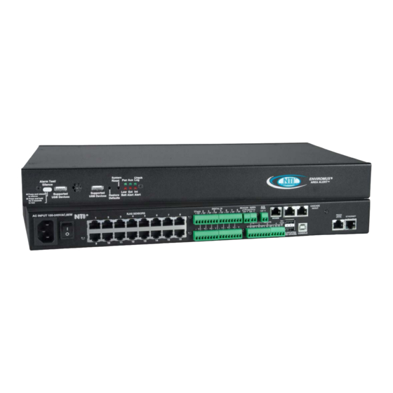
- Page 1 ® ENVIROMUX Series E-16D/-5D/-2D Enterprise Environment Monitoring System Installation and Operation Manual Front and Rear View of E-16D Front View of E-5D Front View of E-2D MAN154 Rev Date 4/30/2020...
- Page 2 TRADEMARK ENVIROMUX is a registered trademark of Network Technologies Inc in the U.S. and other countries. COPYRIGHT Copyright © 2005-2020 by Network Technologies Inc. All rights reserved. No part of this publication may be reproduced, stored in a retrieval system, or transmitted, in any form or by any means, electronic, mechanical, photocopying, recording, or otherwise, without the prior written consent of Network Technologies Inc, 1275 Danner Drive, Aurora, Ohio 44202.
- Page 3 All topics listed below are covered in greater detail throughout this manual, but for instruction that focuses on specific topics, the following is available to you. Click on the Manual # to view the subject. ENVIROMUX E-xD Supplemental Instructions MANUAL # Description SMAN154-01 How to setup Email...
-
Page 4: Table Of Contents
TABLE OF CONTENTS Introduction..................................1 Materials ..................................3 Supported Web Browsers ............................... 4 Features And Functions ..............................5 Installation ..................................7 Mounting Instructions-16D............................7 Mounting Instructions-5D / -2D............................ 8 DIN Rail Mounting..............................9 Sensor Attachment ..............................10 RJ45 Sensor Ports..............................10 Digital In Terminals .............................. - Page 5 Summary Page ............................... 31 Power Supplies ............................... 32 Power Supply Alert Configuration........................... 32 Alarm Summary ..............................35 Internal Sensors..............................36 External Sensors..............................37 External Sensor Configuration..........................42 Specialized Sensors (for E-S420MA-24V Current Sensor Configuration only)............46 Contact Sensors ..............................48 Monitor Output Relay ..............................
- Page 6 Digital Inputs ................................123 Output Relays ................................123 Beacon Port & Siren Port............................123 USB Device Ports ..............................124 Control Serial Port “RS232” ............................. 124 USB-Serial Port “Console” ............................124 Auxiliary Power Port ..............................124 Ethernet Port................................124 Back-Up Battery............................... 124 General Specifications.............................
- Page 7 TABLE OF FIGURES Figure 1- Secure rack mount ears to E-16D ............................7 Figure 2- Mount ENVIROMUX in a rack ............................7 Figure 3- Rotate the tabs for Zero-RU mounting..........................8 Figure 4- Mount E-5D/2D in a rack ..............................8 Figure 5- Mount E-5D/2D to DIN rail- plastic clip ..........................
- Page 8 Figure 51- Status of Digital Input #2 ..............................52 Figure 52- Open configuration from Digital Input page ........................52 Figure 53- Connection that supports Tachometer Sensor ....................... 53 Figure 54- Monitoring Output Relays ............................... 54 Figure 55- Output Relay Status ............................... 54 Figure 56- Output Relay Contact State ............................
- Page 9 Figure 103- Security Configuration- IP Filtering Rules ........................93 Figure 104- System Information page.............................. 94 Figure 105- Update Firmware Page..............................95 Figure 106- Cascade configuration options ............................. 96 Figure 107- Master with local (RS485) slaves ..........................97 Figure 108- Cascade configuration with Ethernet slaves ......................... 97 Figure 109- Configure which Slaves will be connected to the Master ....................
-
Page 10: Introduction
The external sensors sold by NTI will monitor temperature and humidity, monitor AC line voltage, frequency, and current, detect smoke, and much more. The temperature and humidity sensors will provide current readings as well as alerts when thresholds are exceeded. - Page 11 NTI ENTERPRISE ENVIRONMENT MONITORING SYSTEM The E-5D Medium Enterprise Environment Monitoring System and E-2D Small Enterprise Environment Monitoring System have almost the same functionality as the E-16D, just fewer connection points. E-16D vs. E-5D vs. E-2D Feature Differences Feature E-16D...
-
Page 12: Materials
(page 96) See our webpage for the latest sensors available; http://www.networktechinc.com/environment-monitor-16d.html Contact your nearest NTI distributor or NTI directly for all of your cable needs at 800-RGB-TECH (800-742-8324) in US & Canada or 330-562-7070 (Worldwide) or at our website at www.networktechinc.com... -
Page 13: Supported Web Browsers
NTI ENTERPRISE ENVIRONMENT MONITORING SYSTEM SUPPORTED WEB BROWSERS Most modern web browsers should be supported. The following browsers have been tested: Microsoft Internet Explorer 6.0 or higher Mozilla FireFox 1.5 or higher Opera 9.0 Google Chrome Note: If HTTPS pages cannot be viewed in the browser (“The page cannot be displayed”... -
Page 14: Features And Functions
NTI ENTERPRISE ENVIRONMENT MONITORING SYSTEM FEATURES AND FUNCTIONS LABEL (LEDs) DESCRIPTION Pwr- indicates when power to ENVIROMUX is ON (solid ON) and when power failure has occurred (battery power is ON- LED is blinking once per second) Low Batt- indicates that the backup battery is running low on power, disconnected, or in failure... - Page 15 NTI ENTERPRISE ENVIRONMENT MONITORING SYSTEM LABEL CONNECTOR DESCRIPTION Aux Pwr Terminal block for powering an auxiliary device with 12VDC power at 150mA maximum (fuse protected) RS232 AUX RJ45 female for connection of a serial modem or remote RS232 device to be controlled...
-
Page 16: Installation
NTI ENTERPRISE ENVIRONMENT MONITORING SYSTEM INSTALLATION Mounting Instructions-16D The E-16D was designed to either sit on a shelf or be mounted in a rack. For mounting in a rack It includes a rack mount kit to make attachment easy. Attach the ears to the ENVIROMUX using the #6-32x3/16" flat Phillips-head screws (6) provided as shown in the illustration below. -
Page 17: Mounting Instructions-5D / -2D
NTI ENTERPRISE ENVIRONMENT MONITORING SYSTEM Mounting Instructions-5D / -2D The E-5D and -2D can either be placed on a solid surface, mounted to a wall, mounted to a DIN rail or mounted to an accessible surface within rack (Zero-RU). To mount to a wall or other surface, first remove the screws holding the mounting tabs to the rear of the box. -
Page 18: Din Rail Mounting
NTI ENTERPRISE ENVIRONMENT MONITORING SYSTEM DIN Rail Mounting If DIN rail mounting is preferred, and you have purchased the E-5D-D or E-2D-D, then a DIN rail bracket has been pre-installed on the ENVIROMUX. Simply determine where on the DIN rail you want to place the ENVIROMUX and follow the instructions below for attaching it. -
Page 19: Sensor Attachment
NTI ENTERPRISE ENVIRONMENT MONITORING SYSTEM Sensor Attachment Connect the desired sensors (sold separately) to the available ports on the ENVIROMUX. Sensors come with one of two connection methods, RJ45 and individual wires for terminal connection. This section explains both methods of connection. -
Page 20: Digital In Terminals
NTI ENTERPRISE ENVIRONMENT MONITORING SYSTEM Digital In Terminals To connect contact sensors without using RJ45 connectors, terminal blocks have been provided labeled "DIGITAL IN". Two wire switch-only type sensors can be connected to the DIGITAL IN terminals as shown below. If the sensors require a 12V power source to operate, additional 12V and ground terminals have been provided on each model, with restrictions as shown. -
Page 21: Figure 10- Secure Liquid Detection Sensor With Tape
30 seconds). Dry the exposed area of the sensor and the sensor “Value” should change back to “Open” within 30 seconds. If the sensor fails to behave in this manner, contact NTI for support. This completes the testing of the sensor. -
Page 22: Alarm(Beacon/Siren) Connections
NTI ENTERPRISE ENVIRONMENT MONITORING SYSTEM Alarm(Beacon/Siren) Connections Terminals have been provided for connection of the E-BCN-R Beacon and E-SRN-M Siren to use for visual alerts and audible alerts when configured. Devices such as this can be installed in locations best suited to get attention. The terminals for these connections will accept 16-26 AWG wire. -
Page 23: Connect Output Devices
NTI ENTERPRISE ENVIRONMENT MONITORING SYSTEM Connect Output Devices For connection of additional output devices to be controlled by the ENVIROMUX, terminals labeled "Output Relays" have been provided. The contacts will work as switches to either close or open circuits (switch ON or OFF) when used. The “default”... -
Page 24: Terminal Connection For Rs232
NTI ENTERPRISE ENVIRONMENT MONITORING SYSTEM Terminal Connection for RS232 If control via serial connection is going to be used (i.e. using Telnet or SSH), serial control can be achieved using the “USB Console” port (all models) or the “RS232” port (E-16D only) or “RS232 AUX” port (E-5D only). -
Page 25: Ethernet Connection For Remote User Control
NTI ENTERPRISE ENVIRONMENT MONITORING SYSTEM Ethernet Connection for Remote User Control To make a remote connection, over the Ethernet, from anywhere on the local area network, connect a CAT5/5e/6 Ethernet cable with RJ45 male connectors on the ends, wired straight through (pin 1 to pin 1, pin 2 to pin 2, etc.). -
Page 26: Modem Connection
The USB GSM modems that have been tested and are confirmed to be compatible with the ENVIROMUX include: iCON GI1505(M) 3G Modem HiLink E303 3G Modem (NTI # E-3GU) E-Lins M300D or M300W Industrial USB Modem iCON GI0452 3G Modem (NTI# E-3GU-IND) ... -
Page 27: Sms Relay Via Snmp
NTI ENTERPRISE ENVIRONMENT MONITORING SYSTEM SMS Messaging Only When using your modem only for SMS messaging, make sure the SIM card is for GSM communication (not CDMA), configured to send SMS messages, and that it is not locked (some SIM cards are "locked" to search for a specific IMEI number of the phone to operate). -
Page 28: Serial Gsm Modem
NTI ENTERPRISE ENVIRONMENT MONITORING SYSTEM Serial GSM Modem To use a serial modem (E-16D/-5D only), connection of the modem to the ENVIROMUX requires a CAT5 patch cable and RJ45- to-DB9 male adapter (supplied with modem). The modem connects to the “RS232 AUX” port and that port must be configured to use as a GSM Modem (page 68). -
Page 29: Power Connection-E-16D
NTI ENTERPRISE ENVIRONMENT MONITORING SYSTEM Power Connection-E-16D Connect the power cord supplied to the IEC connector on the rear of E-16D. Plug the other end into AC mains and use the switch to power ON ENVIROMUX. Note: The power cord provides an earth ground connection for the case. -
Page 30: Dc Power Option
NTI ENTERPRISE ENVIRONMENT MONITORING SYSTEM DC Power Option The E-16D is available with connections for DC power connection. The E-16D-48V can be connected to a 36~72VDC (48VDC nominal) power supply. The E-16D-24V can be connected to a 18~36VDC (24VDC nominal) power supply. Each has connections on the rear for a user-supplied DC power supply (minimum 27 watt). -
Page 31: Figure 22- Power Connections On E-5D-48Vdp
NTI ENTERPRISE ENVIRONMENT MONITORING SYSTEM The E-5D-48V is available with connections for a 18~72VDC (24 or 48VDC nominal) user-supplied power supply. This is typically used when the ENVIROMUX is installed in a Telecom environment. The E-5D-48V will accept a DC power source with positive or negative polarity. -
Page 32: Remote Rs232 Device Control
NTI ENTERPRISE ENVIRONMENT MONITORING SYSTEM Remote RS232 Device Control The “RS232 AUX” port can be used to connect a remote serially-controlled device (E-5D and -16D only). Once connected, a user named “rs232” can login to the ENVIROMUX from a command prompt and begin sending commands directly to the serial device. -
Page 33: Figure 26- Connection To Serial Device Successful
NTI ENTERPRISE ENVIRONMENT MONITORING SYSTEM 3. Open a SSH client program (Putty, Tera Term, etc.), connect to the ENVIROMUX by entering the IP address of the ENVIROMUX. Note: Make sure your SSH client is a recent version. Older SSH clients will not work with the ENVIROMUX. -
Page 34: Overview - Use And Operation
Manual) Initially, IP configuration will be the easiest to change using the NTI Device Discovery Tool, which will search for NTI devices on the user’s network and allow IP assignment to them through its web interface. Other settings for subnet mask and default gateway may also be configured (see page 28). -
Page 35: Data And Event Logging
NTI ENTERPRISE ENVIRONMENT MONITORING SYSTEM Data and Event Logging The ENVIROMUX can log sensor readings, sensor alerts, alert handling, sensor connections/removals, and user logins/logouts. The logs can be viewed at any time through the web interface (page 113). Additionally, as entries are generated, they can be emailed or sent as SNMP traps. -
Page 36: Out-Of-Box Operation
NTI ENTERPRISE ENVIRONMENT MONITORING SYSTEM Out-of-Box Operation The operation of the unit directly out of the box is nearly identical to the Power-on/Reset operation. However, information about the unit will only be able to be monitored and controlled through the “RS232” or “CONSOLE” ports until valid network settings are assigned to the device (see page 74). -
Page 37: Device Discovery Tool
Tip: If your Windows program asks which program to open the NTIDiscover.jar file with, select the Java program. Figure 27- Device Discovery Tool Click on the “Detect NTI Devices” button to start the discovery process. After a short time, the tool will display all NTI devices on your network, along with their network settings. -
Page 38: Use And Operation Via Web Interface
IP address to enter when logging in to the ENVIROMUX. Note: The computer using the Device Discovery Tool and the NTI Device must be connected to the same subnet in order for the Device Discovery Tool to work. If no devices are found, the message “No Devices Found” will be displayed. -
Page 39: Monitoring
NTI ENTERPRISE ENVIRONMENT MONITORING SYSTEM With a successful log in, a screen similar to the following will appear: Figure 29- Summary page The initial page includes the Summary page, and a menu to the left with access to all pages used to manage the functions of the ENVIROMUX. -
Page 40: Summary Page
NTI ENTERPRISE ENVIRONMENT MONITORING SYSTEM Summary Page The Summary Page displays the data for all categories of monitored items: Category Description Internal Sensors there are three inside the ENVIROMUX Sensors sensors that connect to the RJ45 connectors Digital Inputs sensors that connect to the terminals "Digital In"... -
Page 41: Power Supplies
NTI ENTERPRISE ENVIRONMENT MONITORING SYSTEM Power Supplies The status of the power supply can be seen, and when a dual power supply model is present, both power supplies will be shown. Click on the power supply to open a web page that displays the type of item sensed, the status of the power supply, and the time and date of the most recent alert sent regarding the power supply. -
Page 42: Figure 33- Power Supply Alerts Configuration-Part 2
NTI ENTERPRISE ENVIRONMENT MONITORING SYSTEM Figure 33- Power Supply alerts configuration-part 2 Alert Settings Group: This is the group (or groups) of sensors the power supply sensor will belong to. Users that subscribe to alerts from this group will receive alerts from the power supply sensor. Each sensor can be configured to send alerts. Up to 8 sensor groups can be defined. - Page 43 NTI ENTERPRISE ENVIRONMENT MONITORING SYSTEM Alert Notifications The alert can be configured to notify one or more users via email, SNMP traps (v1,v2c, v3), Syslog messages, or SMS alerts. It can also activate an audible siren, or an alarm beacon.
-
Page 44: Alarm Summary
NTI ENTERPRISE ENVIRONMENT MONITORING SYSTEM Alarm Summary To view only those sensors in an alarm state, select the Alarm Summary page under Monitoring. To enable or disable all alerts, use the "Alert Manage" buttons at the bottom of this page. -
Page 45: Internal Sensors
NTI ENTERPRISE ENVIRONMENT MONITORING SYSTEM Internal Sensors E-16D and -5D have three on-board sensors, which are permanently present: one temperature sensor one humidity sensor one power (battery) sensor Internal sensors are monitored and fully configurable just as External Sensors are (see Figure 37 and page 42) except that they do not have a box for "Enable Disconnection Alert"... -
Page 46: External Sensors
NTI ENTERPRISE ENVIRONMENT MONITORING SYSTEM ASHRAE Recommendation According to ASHRAE's committee 9.9 for mission critical facilities, a class A1 data center can range in temperature from 59°F to 89.6°F and in relative humidity from 20% to 80%. This is very important for energy efficiency. -
Page 47: Figure 36- External Sensor Reading
NTI ENTERPRISE ENVIRONMENT MONITORING SYSTEM minimum level maximum level center of range minimum non-critical threshold maximum critical threshold minimum critical threshold maximum non-critical threshold Figure 36- External Sensor Reading If the sensor is in alert status, the user has the option to either acknowledge the alert or dismiss it. -
Page 48: Figure 37- Sensor Configuration Page (1)
NTI ENTERPRISE ENVIRONMENT MONITORING SYSTEM Figure 37- Sensor Configuration Page (1) -
Page 49: Figure 38- Sensor Configuration Page (2)
NTI ENTERPRISE ENVIRONMENT MONITORING SYSTEM Figure 38- Sensor Configuration Page (2) -
Page 50: Figure 39- Sensor Configuration Page (3)
NTI ENTERPRISE ENVIRONMENT MONITORING SYSTEM When using SMS messaging, if special characters (other than English) are desired, in order to receive them via SMS, the language setting of the E-xD must be set to any language other than English (see... -
Page 51: External Sensor Configuration
NTI ENTERPRISE ENVIRONMENT MONITORING SYSTEM Figure 40- Sensor Configuration Page (4) External Sensor Configuration Sensor Settings Description Description The description of the sensor that will be viewed in the Summary page and in the body of alert messages Units This lets the operator choose between Celsius and Fahrenheit as the temperature measurement unit. - Page 52 NTI ENTERPRISE ENVIRONMENT MONITORING SYSTEM Schedule Settings Schedule Type Always active- sensor will react to alert conditions at all hours of each day Active during defined times- sensor will only react to alert conditions during times as outlined below Start Day...
-
Page 53: Figure 41- Chart To Setup Alert Notification
NTI ENTERPRISE ENVIRONMENT MONITORING SYSTEM Alert Settings (Applies to Critical and Non-Critical Alerts except where noted) (Cont’d) Associated Output Relay You can associate the sensor with the operation of the output relay, or not. By Default, the operation of an output relay can only be associated with one sensor or IP Device. - Page 54 NTI ENTERPRISE ENVIRONMENT MONITORING SYSTEM Alert Settings Alert Delay: The alert delay is an amount of time the sensor must be in an alert condition before an alert is sent. This provides some protection against false alarms. The Alert Delay value can be set for 0-999 seconds or minutes.
-
Page 55: Specialized Sensors (For E-S420Ma-24V Current Sensor Configuration Only)
NTI ENTERPRISE ENVIRONMENT MONITORING SYSTEM Specialized Sensors (for E-S420MA-24V Current Sensor Configuration only) When a E-S420MA-24V Current Sensor is connected to the ENVIROMUX, the summary page will update with two sensor names of the Type “Current”. Various types of sensors can be connected to an E-S420MA-24V. In order to better define the sensor on the Summary Page, in SNMP traps, or in an MIB browser, click on the “Edit”... - Page 56 NTI ENTERPRISE ENVIRONMENT MONITORING SYSTEM Most of the sensor settings are the same as any other sensor configuration (page 42) but there are some differences: Sensor Settings Description Associate Sensor Select if the Type “Current” should be replaced by the sensor type to be entered in the next box Associated Sensor Type Enter the “Type”...
-
Page 57: Contact Sensors
NTI ENTERPRISE ENVIRONMENT MONITORING SYSTEM Contact Sensors Contact Sensors are sensors that close or open a contact according to the sensor condition. Their presence and their type cannot be automatically detected by the RJ45 Sensor port. The sensors have to be manually added to the unit list by the administrator or a user with administrator privileges. -
Page 58: Figure 46- Contact Sensor Configuration Page
NTI ENTERPRISE ENVIRONMENT MONITORING SYSTEM Many of the settings found in the RS485 configuration page are not present because they do not apply to contact sensors. As such, only “Critical Alert Settings” apply (see descriptions on page 42) and non-critical alert settings are omitted altogether. -
Page 59: Figure 47- Contact And Digital Alert Settings
NTI ENTERPRISE ENVIRONMENT MONITORING SYSTEM Change Global Alert Status on triggering this sensor: Found under Critical Alert Settings, this feature enables the user to configure this sensor to cause the following changes to take effect: A) No Alert Changes: make no changes to how alerts are managed (the default setting) B) Enable Global Alerts: force all alert settings in effect to be acted upon as configured (if another sensor has disabled alerts, this setting will re-enable them). -
Page 60: Figure 48- Digital Input Sensors
NTI ENTERPRISE ENVIRONMENT MONITORING SYSTEM Digital Inputs The “Digital In” terminals (page 11) are for easy installation of contact sensors (as opposed to using the RJ45 sensor ports). Connect up to 8 different contact sensors having either 2-wire contacts (for open or closed circuit sensing) or 4-wire contacts (for open or closed circuit sensors requiring 12V power supplies to operate). -
Page 61: Figure 50- Configure New Sensor
NTI ENTERPRISE ENVIRONMENT MONITORING SYSTEM Once the connector is selected, a configuration window will open providing fields for the additional information available to setup the sensor. Tip: To test a Digital Input sensor, after the input and alert settings have been properly configured, change the Normal Status to the opposite of what "Normal"... -
Page 62: Figure 53- Connection That Supports Tachometer Sensor
NTI ENTERPRISE ENVIRONMENT MONITORING SYSTEM Cycle Sensor Power A “Cycle Sensor Power” button is also provided (see Figure 51) for each sensor connected to the “Digital In” terminals (locally- connected Digital Inputs only). To momentarily disrupt power to any sensor connected to a Digital Input terminal, click on this button. -
Page 63: Monitor Output Relay
NTI ENTERPRISE ENVIRONMENT MONITORING SYSTEM Monitor Output Relay Output relays are provided to control external devices with a rating of up to 1A, 30VDC or 0.5A, 125VAC. Each relay state is monitored to be either inactive (relay is at rest; contacts as indicated by product markings) or active (relay is energized; contacts are opposite that of product markings). -
Page 64: Figure 57- Configure Output Relay
NTI ENTERPRISE ENVIRONMENT MONITORING SYSTEM To change settings for the output relay and whether or not a state change should generate an alert message, click the “Configure” button. These names are just names assigned under “Group Names” (page 79) and have no other specific association. -
Page 65: Ip Devices
NTI ENTERPRISE ENVIRONMENT MONITORING SYSTEM IP Devices Up to 64 IP addresses can be assigned to be monitored by ENVIROMUX. They will be displayed under the Monitoring->IP Devices item in the left side menu. The ENVIROMUX will periodically ping (test) these addresses to determine whether or not they are up and running. -
Page 66: Figure 60- Ip Device Configuration
NTI ENTERPRISE ENVIRONMENT MONITORING SYSTEM Figure 60- IP Device Configuration IP Device Settings Description Description The description of the IP Device that will be viewed in the Summary page and in the body of alert messages IP Address The IP address of the IP Device... -
Page 67: Figure 61- Ip Device Configuration-More
NTI ENTERPRISE ENVIRONMENT MONITORING SYSTEM When using SMS messaging, if special characters (other than English) are desired, in order to receive them via SMS, the modem SMS format must be set to PDU (see page 70) Figure 61- IP Device Configuration-more... - Page 68 NTI ENTERPRISE ENVIRONMENT MONITORING SYSTEM Group Settings Description Group Assign the device IP to any or all groups 1 -8 (see also page 44) Schedule Settings Schedule Type Always active- system will react to alert condition at all hours of each day...
-
Page 69: Ip Sensors
NTI ENTERPRISE ENVIRONMENT MONITORING SYSTEM Data Logging Add to data log This is a check-box that lets the user decide if the data sampled should be recorded in the Data Log. Logging Period Enter the time period between logged measurements IP Sensors Sensors connected to an E-MICRO-T(RHP) or E-1W can be monitored and configured from the E-xD interface. -
Page 70: Snmp Sensors
NTI ENTERPRISE ENVIRONMENT MONITORING SYSTEM SNMP Sensors The ENVIROMUX is able to poll and report the status of conditions from up to 32 third-party SNMP devices (requires firmware version 2.61 and later). The Summary page provides a link to view the status of SNMP monitored conditions of network-connected devices and using Smart Alerts or Events the user can be notified when conditions are outside of desired parameters. -
Page 71: Figure 66- Snmp Sensor Configuration Page
NTI ENTERPRISE ENVIRONMENT MONITORING SYSTEM Data Logging Add to data log This is a check-box that lets the user decide if the data sampled should be recorded in the Data Log. Logging Period Enter the time period between logged measurements... -
Page 72: Figure 67- Events Page Under Smart Alerts
NTI ENTERPRISE ENVIRONMENT MONITORING SYSTEM Once the Sensor is setup to be polled, alerts can be configured using the Smart Alert- Event settings. Click on "Create New Event". Figure 67- Events page under Smart Alerts In the example (right), the Event... -
Page 73: Ip Cameras
NTI ENTERPRISE ENVIRONMENT MONITORING SYSTEM IP Cameras The IP Camera page displays the video snapshots of up to 8 monitored IP cameras. ENVIROMUX will display the video from specified IP addresses and provide images at 320 x 240 resolution. Place a name, the URL or IP address of the link, and the name of the image taken by the camera in the blocks provided (examples below). -
Page 74: Figure 70- Ip Camera Configuration
NTI ENTERPRISE ENVIRONMENT MONITORING SYSTEM Once this is configured, test to see if images come via email. (See below) If not, your camera may require “Digest Access Authentication” to work. In this case, place a checkmark in “Enable If you Enable HTTP Digest Access”. -
Page 75: Administration
NTI ENTERPRISE ENVIRONMENT MONITORING SYSTEM Administration From the Administration section there are several sub sections for configuring the ENVIROMUX: System Fields for applying time zone, date, time, NTP server, backup and restore configuration settings and settings for the “RS232 AUX” port... -
Page 76: Figure 72- Configuration Backup And Restore
Note: If “Restore Defaults” is used, the IP address will also be restored to its default address (192.168.1.21) with a login name “root” and password “nti”. To restore the root password to “nti” without having to restore all default settings, contact NTI for assistance. -
Page 77: Figure 73- Select What Will Be Displayed On Connected Usb Lcd Monitor
NTI ENTERPRISE ENVIRONMENT MONITORING SYSTEM USB LCD Display Select Screen Select what should be displayed on a USB LCD monitor when plugged into a USB port on the ENVIROMUX (see Figure 73) An USB LCD monitor can be connected to any of the USB Type A ports (page 121). -
Page 78: Figure 75- System Configuration-Continued
NTI ENTERPRISE ENVIRONMENT MONITORING SYSTEM Figure 75- System Configuration-continued RSA Public Key Click on this button to save an authentication key to a Linux or Unix machine. In order to configure an Event or Smart Alert to cause an SSH command to be sent to a Linux or Unix machine automatically (see page 105 or page 109), the Linux or Unix computer must be configured to accept the command from the ENVIROMUX. -
Page 79: Figure 76- Disable External Sensor Graph
NTI ENTERPRISE ENVIRONMENT MONITORING SYSTEM Figure 76- Disable External Sensor Graph Disable Sensor Graphs When checking the status of external RS485 sensors, by default a graph is displayed with the accumulative readings for that sensor (see page 38). The display of that information will take some additional time for your browser to provide. If you don’t wish to have that graph displayed and would rather speed up the status information of these sensors, you can place a checkmark in “Disable Sensor Graphs”. -
Page 80: Administration-Enterprise Setup
NTI ENTERPRISE ENVIRONMENT MONITORING SYSTEM Administration-Enterprise Setup The Enterprise Setup page (Administration ->Enterprise) is used to enter basic company information to be applied to the body of alerts. Enter the information to the blocks provided with your company name, location, the contact person that alert e-mails should refer to, the phone number to reach them, and the e-mail address assigned to the E-16D. -
Page 81: Figure 79- Gsm Modem Status
NTI ENTERPRISE ENVIRONMENT MONITORING SYSTEM GSM Modem Status If a modem has not yet been connected, the message "Not Available" will appear on the setup menu. The modem must be powered ON and connected before the ENVIROMUX is powered ON. -
Page 82: Figure 81- Example Of Plain Text Sms Test Message
NTI ENTERPRISE ENVIRONMENT MONITORING SYSTEM In the same screen as the GSM Modem Status is the selection for the SMS message format. Three settings are available for this format: Default: With this setting, if your language setting is English, the SMS messages will be sent in Plain Text. -
Page 83: Administration-Network Setup
NTI ENTERPRISE ENVIRONMENT MONITORING SYSTEM Administration-Network Setup From the Network Configuration page (Administration->Network) the administrator can either choose to have the IP address and DNS information filled in automatically by the DHCP server (the default setting), or manually fill in the fields (use a static address). Settings can be entered for either the IPv4 or IPv6 protocols. -
Page 84: Figure 85- Configure Smtp, Snmp, And Security Settings
NTI ENTERPRISE ENVIRONMENT MONITORING SYSTEM Common SMTP Port numbers: Default: 25 (Not secure) SSL: 465 (Secure) TLS: 587 (Secure) Contact your network administrator for required settings. For a guide to setting up the ENVIROMUX for sending email messages, see page 119. -
Page 85: Figure 86- Configure 3G Data Connection
NTI ENTERPRISE ENVIRONMENT MONITORING SYSTEM Figure 86- Configure 3G Data Connection VLAN Settings Description Enable 802.1Q VLAN Select between "Disabled" (the default) or "Enabled" VLAN ID Enter a number between 0-4095 for your VLAN ID SMTP Settings SMTP Server Enter a valid SMTP server name (e.g. yourcompany.com) - Page 86 NTI ENTERPRISE ENVIRONMENT MONITORING SYSTEM Note: When using only a secure access configuration (“Enable HTTP Access” is NOT checked), if you intend to connect to the ENVIROMUX from a location outside the local area network, make sure the firewall on the local area network is configured to allow traffic through the port assigned to HTTPS requests.
-
Page 87: Figure 87- Ddns Settings
NTI ENTERPRISE ENVIRONMENT MONITORING SYSTEM Note: If the 3G Data connection is enabled as the primary internet connection, make sure that a reliable signal exists between the modem and service provider. Otherwise attempts made by the ENVIROMUX to communicate with devices on the network may be delayed and cause unnecessary alert messages. -
Page 88: Figure 88- How To Setup Snmp To Control Output Relays
NTI ENTERPRISE ENVIRONMENT MONITORING SYSTEM 1. Configure the ENVIROMUX (Network Settings) Note: enter same values from ENVIROMUX to the MIB browser (private) (public) 2. Configure the MIB browser 4. Identify which Output to 3. Expand the tree to view the... -
Page 89: Figure 89- Xoauth- Generate Verification Url
NTI ENTERPRISE ENVIRONMENT MONITORING SYSTEM XOAUTH Settings On the Network Configuration page is a section for XOAUTH Settings, used to enable automatic user authentication verification when the SMTP server requires XOAUTH2 authentication (i.e. Gmail). Note: Make sure your SMTP settings are entered correctly (username, password, “Use Authentication” is checked, etc.) before proceeding (page 75). -
Page 90: Figure 91- Xoauth- Accept Prompt To Manage Your Mail
NTI ENTERPRISE ENVIRONMENT MONITORING SYSTEM 4. You will be prompted to login to the Gmail account you have setup for the ENVIROMUX. Once logged in, Gmail will ask if you want the ENVIROMUX to be able to view and manage email from this account. Click on “Accept”. -
Page 91: User Configuration
NTI ENTERPRISE ENVIRONMENT MONITORING SYSTEM User Configuration The Users page is a list of all configured users of the ENVIROMUX. A maximum of 15 users (other than root) can be configured. From this page the root user (or any user with administrator rights) can choose to add more users, go to the user configuration page to edit a user’s access to the ENVIROMUX, or delete a user from the list. -
Page 92: Figure 95- More User Settings
NTI ENTERPRISE ENVIRONMENT MONITORING SYSTEM Figure 95- More user settings... -
Page 93: Figure 96- More User Settings
NTI ENTERPRISE ENVIRONMENT MONITORING SYSTEM Account Settings Description Username Enter the desired username for this user Admin Place a checkmark here if this user should have administrative privileges Operator Place a checkmark here if this user should have operator privileges... -
Page 94: Figure 97- More User Settings
NTI ENTERPRISE ENVIRONMENT MONITORING SYSTEM Schedule Settings Schedule Type Always active- user will receive messages at all hours of each day Daily active during defined times- user will receive message every day but during only the times specified Active during defined times- user will only receive alert messages during days and times as... -
Page 95: Figure 98-Summary Page For User Without Admin Privileges
NTI ENTERPRISE ENVIRONMENT MONITORING SYSTEM More about User Privileges The root user (or any user with administrator rights) can change the root password and configure how the root user will receive alert messages. Users with administrative rights can change all configuration settings except for the root user name. -
Page 96: Group Names
NTI ENTERPRISE ENVIRONMENT MONITORING SYSTEM Group Names Group names can be applied instead of the group numbers in the event an association is desired other than “Group 0x” . For each group (1-8), a name can be applied containing up to 64 English or 21 Kanji (Japanese) characters. -
Page 97: Security
NTI ENTERPRISE ENVIRONMENT MONITORING SYSTEM Security Access to the web interface on the ENVIROMUX can be through standard methods (enable HTTP access- page 76) or limited to secure access only (disable HTTP access and only allow HTTPS access which is always enabled by default). Security in the ENVIROMUX can be managed one of three ways;... - Page 98 NTI ENTERPRISE ENVIRONMENT MONITORING SYSTEM User Authentication Mode Select Local to use authentication based on passwords in the ENVIROMUX user configuration Select LDAP to use authentication based on passwords in an LDAP server Select “Certificate+Login” when authentication requires the connecting PC to hold a valid certificate Select “Radius +Local”...
-
Page 99: Using A Radius Server
NTI ENTERPRISE ENVIRONMENT MONITORING SYSTEM Using a RADIUS Server 1. The dictionary.nti file (this file has an .nti extension) must be saved to a location on the PC the RADIUS server is run from. (This file is found on the ENVIROMUX download page (http://www.networktechinc.com/download/d-environment-monitor-... - Page 100 RADIUS server will adjust the ENVIROMUX user account password to match the one in the RADIUS server. All radius property names are optional except for "NTI-User-Enable := 1" . For a detailed list of available property values, please check dictionary.nti file.
-
Page 101: Figure 102- Security Configuration-X509 Certificate
NTI ENTERPRISE ENVIRONMENT MONITORING SYSTEM X509 Certificate Authority A Certificate Authority (CA) needs to be used to sign the server certificate describe above. This Certificate Authority can be created as a self-signed certificate in "CRT" format. It can also be given to you by an external Certificate Authority in "CRT" or "PEM"... -
Page 102: Figure 103- Security Configuration- Ip Filtering Rules
NTI ENTERPRISE ENVIRONMENT MONITORING SYSTEM IP Filtering Included in the Security Configuration options is IP Filtering. IP Filtering provides an additional mechanism for securing the ENVIROMUX. Access to the ENVIROMUX network services (SNMP, HTTP(S), SSH, Telnet) can be controlled by allowing or disallowing connections from various IP addresses, subnets, or networks. -
Page 103: System Information
NTI ENTERPRISE ENVIRONMENT MONITORING SYSTEM More on IP Filtering The most common approach is to only allow “white-listed” IP addresses, subnets, or networks to access the device while blocking all others. The IP Filters are processed sequentially from top to bottom, so it is important to place the most precise rules at the top of the list and the most generic rules at the bottom of the list. -
Page 104: Administration- Firmware
Note: In the event the ENVIROMUX firmware should be corrupted, such that connection through the web interface is no longer possible, contact NTI for instruction and recovery files to access the ENVIROMUX and restore the firmware using a TFTP server... -
Page 105: Advanced-Cascade Configuration
NTI ENTERPRISE ENVIRONMENT MONITORING SYSTEM Advanced-Cascade Configuration From the Administration->Advanced>Cascade menu, the administrator can configure the ENVIROMUX to either be a master system, If one E-xD in a cascaded system is at firmware When cascading via Ethernet, the E-16D, - ... -
Page 106: Figure 107- Master With Local (Rs485) Slaves
NTI ENTERPRISE ENVIRONMENT MONITORING SYSTEM 2. Connect the RS485 slaves to the master as shown below using CAT5/5e/6 patch cables with RJ45 connectors wired straight thru (pin 1 to pin 1, pin 2 to pin 2, etc. ). The maximum total distance from the master to the final slave unit cannot exceed 4000 feet. -
Page 107: Figure 109- Configure Which Slaves Will Be Connected To The Master
NTI ENTERPRISE ENVIRONMENT MONITORING SYSTEM 4. From the Cascaded Settings page of the Master unit, enter a checkmark for each slave that will be present in the configuration. This enables the slave and defines the slave sequence (number 1-4) as it will appear on the sensor summary page. - Page 108 NTI ENTERPRISE ENVIRONMENT MONITORING SYSTEM Alert Settings Group Just as sensors are assigned to a group, a Slave loss alert can be assigned to a group. In the event a Slave loses connection with the Master, for any reason, an alert notification will be sent to all users subscribing to alerts from this sensor group.
-
Page 109: Figure 111- Portion Of Summary Page From A Master With A Slave
NTI ENTERPRISE ENVIRONMENT MONITORING SYSTEM Slave Sensors Slave Sensors Slave Sensors Figure 111- Portion of Summary Page from a Master with a Slave From the Summary page of the Master (above), sensors connected to Slave unit can be viewed and configured just as if they... -
Page 110: Reboot The System
NTI ENTERPRISE ENVIRONMENT MONITORING SYSTEM Reboot the System The ENVIROMUX can be remotely rebooted by anyone with administrative privileges. To view the Reboot System page, select Reboot in the Administration section of the main menu. Click the Reboot Now button to cause the ENVIROMUX to reboot. -
Page 111: Smart Alerts
NTI ENTERPRISE ENVIRONMENT MONITORING SYSTEM Smart Alerts Smart Alerts enable the ENVIROMUX to contact users when specially configured circumstances exist for defined sensors. Smart Alerts will respond to 1 or more alert conditions independent of the alert configurations for each sensor configured on page 38. -
Page 112: Figure 116- Configuration Options For New Event
NTI ENTERPRISE ENVIRONMENT MONITORING SYSTEM Figure 116- Configuration options for new event Depending upon the type of sensor chosen, various event settings can be configured that will cause an event to be logged. In the example above, if the temperature sensor sees a temperature greater than 90.0 degrees C for more than 30 seconds, an event will be logged. - Page 113 NTI ENTERPRISE ENVIRONMENT MONITORING SYSTEM Event Settings Description The description of the sensor that will be viewed in the Summary page and in the body of alert messages Threshold (for RJ45 sensors) The threshold value of the measured unit that will trigger an event Note: The trigger value can be a value that is considered a sensor’s “normal”...
-
Page 114: Figure 117- Event Configuration Options Continued
NTI ENTERPRISE ENVIRONMENT MONITORING SYSTEM Figure 117- Event Configuration options continued Remote SSH Commands Remote address Enter the IP address or host name of the Linux or Unix computer to be sent a command via an SSH connection. Enable command on event... -
Page 115: Figure 118- Smart Alert Summary Page
NTI ENTERPRISE ENVIRONMENT MONITORING SYSTEM With Events defined, Smart Alerts (up to 20) can be configured to use Event combinations to send alert messages. Figure 118- Smart Alert summary page From the side menu, select “Smart Alerts”, and “Smart Alerts” again. On the Smart Alerts page, click on “Add New Smart Alert”. -
Page 116: Figure 120- Smart Alert Configuration- Continued
NTI ENTERPRISE ENVIRONMENT MONITORING SYSTEM DESCRIPTION Description Use the default description provided or enter the description you want to see on notifications received. OR Events Available Events Select from the predefined available Events (Figure 114) to have OR logic applied to a triggered... -
Page 117: Figure 121- Smart Alert Configuration- Continued
NTI ENTERPRISE ENVIRONMENT MONITORING SYSTEM Figure 121- Smart Alert configuration- continued Smart Alert Notifications Notify Again Time Enter the amount of time in seconds, minutes, or hours (1-999) before an alert message will be repeated Notify on Return to Normal The user can also be notified when the Smart Alert conditions have returned to the normal (non- triggered state) by selecting the "Notify when return to normal"... -
Page 118: Figure 122- Smart Alert Configuration- Continued
NTI ENTERPRISE ENVIRONMENT MONITORING SYSTEM Figure 122- Smart Alert Configuration- continued Remote SSH Commands Remote address Enter the IP address or host name of the Linux or Unix computer to be sent a command via an SSH connection. Enable command on event... -
Page 119: Figure 123- Event Logical Function Diagram
NTI ENTERPRISE ENVIRONMENT MONITORING SYSTEM More on Logical Functions Using Logical Functions, you can select how to use or not use the reported state of an Event. You can combine the information from multiple Events to achieve an end result. -
Page 120: Figure 124- Examples Of Smart Alert Conditions
NTI ENTERPRISE ENVIRONMENT MONITORING SYSTEM Figure 124- Examples of Smart Alert conditions Basic Application Example You want a temperature sensor to activate one output relay when too hot, and another output relay when too cold. (This configuration can be done with either an E-5D, E-16D, or a connected E-DI16DOR16). In the individual sensor configuration, only one relay action can be created. -
Page 121: Log
NTI ENTERPRISE ENVIRONMENT MONITORING SYSTEM From the Log section there are three sub sections for configuring the ENVIROMUX: View Event Log View a log listing the date and time of events such as startups, shut downs, user logins View Data Log... -
Page 122: View Data Log
NTI ENTERPRISE ENVIRONMENT MONITORING SYSTEM Example of an Event Log Message: TIME: 07-27-2012 02:15:44 AM ENTERPRISE: E-16D Unit 1 LOCATION: Engineering BRANCH: RACK: CONTACT: NTI DESCRIPTION: Temperature 1 CONNECTOR: 1 TYPE: Temperature MESSAGE: Sensor value crossed over non-critical thresholds VALUE: 85.0F... -
Page 123: View Usb Data Log
NTI ENTERPRISE ENVIRONMENT MONITORING SYSTEM View USB Data Log If any Data Logs have been saved to the USB flash drive connected to a USB port on the ENVIROMUX, a list of those logs can be viewed and opened for review. -
Page 124: Log Settings
NTI ENTERPRISE ENVIRONMENT MONITORING SYSTEM Figure 128- View Images saved on USB Flash Drive Log Settings The Log Settings page (Figure 129) provides settings for how the ENVIROMUX will react when its Data and Event logs reach capacity. The Event Log settings include a Logging Level that can be configured to log different amounts of information: ... -
Page 125: Figure 129- Log Settings Page
NTI ENTERPRISE ENVIRONMENT MONITORING SYSTEM The Data and/or Event log can be set to send alerts to users via email, syslog, SMS and/or SNMP traps once it has reached 90% of capacity, allowing them time to react. The Data log can also be set to... -
Page 126: Figure 130- Mount A Usb Flash Drive
NTI ENTERPRISE ENVIRONMENT MONITORING SYSTEM Log to USB Flash Settings Event and Data log messages are automatically sent to users as configured above in addition to being recorded in the logs. The logs can also be downloaded as a tab-delimited plain text file. If a USB flash drive is present (it doesn’t matter which of the 4 ports it is plugged-into), logs will also be recorded on the flash drive to make them portable provided the feature is enabled. -
Page 127: Support
You must have Adobe Reader installed on your PC to open this. The Downloads link will take you to the Firmware Downloads page for the ENVIROMUX on the NTI website. All versions of firmware and MIB files for the ENVIROMUX will be found there, available for immediate download to your PC. -
Page 128: Front Panel Controls And Led Indicators
NTI ENTERPRISE ENVIRONMENT MONITORING SYSTEM FRONT PANEL CONTROLS AND LED INDICATORS Figure 134- Front panel Front Panel LED Status Chart LED Label Status Meaning No Power Solid ON AC Power is ON Blinking slowly AC Power has failed, Battery backup (pg. 120) is ON (once /second) (The LED will not blink if the unit is powered OFF by the switch.) -
Page 129: Alarm Test/Silence Button
If the battery fails to charge or if the battery's output voltage drops from 12VDC to below 10.7 volts, the "Low Batt" LED will blink. The battery will automatically be disconnected from the system. If this happens, the battery must be replaced. Contact NTI to arrange for return and service. -
Page 130: Usb Port
NTI ENTERPRISE ENVIRONMENT MONITORING SYSTEM USB PORT The ENVIROMUX are each equipped with USB Type A female ports on the front and rear panel for connection of a USB flash drive, a GSM modem or for receiving alert messages via SMS, or a USB LCD Monitor (page 68). -
Page 131: Mobile Summary Page
NTI ENTERPRISE ENVIRONMENT MONITORING SYSTEM MOBILE SUMMARY PAGE The user can login to the ENVIROMUX through the browser on a smart phone or similar device to view a Summary Page for the sensor status (below). To login, type the current IP address of the ENVIROMUX into the address bar of the browser (default IP address used in the example below): http://192.168.1.21/... -
Page 132: E-16D Specifications
NTI ENTERPRISE ENVIRONMENT MONITORING SYSTEM E-16D SPECIFICATIONS Front Panel Interface LEDs ..............Green – Power, Solid for Main power, flashing for Backup power .............Red – Low Bat (solid for charging battery, blinking for fault) .............Green – Check Log …………………………………………….Green – AUX (not used) .............Red –... -
Page 133: Usb Device Ports
Battery Operational Time .......1 hr, fully loaded; 30 min. after ‘Low Bat’ LED illuminates Battery Charging Time ........32 hrs (from fully discharged to fully charged). Replaceable...........Yes – can be replaced by authorized personnel only (NTI) General Specifications Power Input............110/220VAC, 50 – 60 Hz, 45W Operating Temperature........32... -
Page 134: E-5D Specifications
NTI ENTERPRISE ENVIRONMENT MONITORING SYSTEM E-5D SPECIFICATIONS User Interface LEDs ..............Green – Power (solid when ENVIROMUX is powered ON) .............Red – Fault (solid when any sensor is in alert) RJ45 Sensor Inputs Connector ............RJ45 connector Voltage Supply..........5VDC and 12VDC Signal Type............RS485 for RS485 sensors; 2-wire for contact sensors Max. -
Page 135: Usb-Serial Port "Console
NTI ENTERPRISE ENVIRONMENT MONITORING SYSTEM USB-Serial Port “Console” Connector ............USB Type B Female Supported Signals .........D+ ,D- Baud Rate............max 115,200 bps Data Format...........8 bits Parity..............no parity Stop Bits ............1 stop bits ESD Protection ..........IEC1000-4-2 Auxiliary Power Port Connector ............Detachable terminal block-plug-in, 1x2 contacts Wire Range............14-22 AWG... -
Page 136: E-2D Specifications
NTI ENTERPRISE ENVIRONMENT MONITORING SYSTEM E-2D SPECIFICATIONS User Interface LEDs ..............Green – Power (solid when ENVIROMUX is powered ON) .............Red – Fault (solid when any sensor is in alert) RJ45 Sensor Inputs Connector ............RJ45 connector (2) Voltage Supply..........5VDC and 12VDC Signal Type............RS485 for RS485 sensors;... -
Page 137: Auxiliary Power Port
NTI ENTERPRISE ENVIRONMENT MONITORING SYSTEM Auxiliary Power Port Connector ............Detachable terminal block-plug-in, 1x2 contacts Wire Range............16-26 AWG Voltage Output..........12VDC+/-10% Current Output ..........500mA ESD Protection ..........IEC 61000-4-2 Fuse Protection..........Resetable poly fuse – 1.1A hold, 1.95A trip; 16VDC max. Ethernet Port Connector ............RJ45 Female Connection Speed .........10/100 Base-T... -
Page 138: Port Assignments
NTI ENTERPRISE ENVIRONMENT MONITORING SYSTEM PORT ASSIGNMENTS Here are the default ports used by the ENVIROMUX: HTTP HTTPS Telnet SNMP (machine configuration & sensor data) SNMP (traps) MODBUS (default port) SYSLOG ... -
Page 139: Wiring Methods
NTI ENTERPRISE ENVIRONMENT MONITORING SYSTEM WIRING METHODS RS485 Sensor Cable The CAT5 connection cable between the ENVIROMUX and the external RS485 Sensors (page 10) is terminated with RJ45 connectors and must be wired according to the EIA/TIA 568 B industry standard. Wiring is as per the table and drawing below. -
Page 140: Troubleshooting
NTI ENTERPRISE ENVIRONMENT MONITORING SYSTEM TROUBLESHOOTING Each and every piece of every product produced by Network Technologies Inc is 100% tested to exacting specifications. We make every effort to insure trouble-free installation and operation of our products. If problems are experienced while installing this product, please look over the troubleshooting chart below to see if perhaps we can answer any questions that arise. - Page 141 500 mA. (i.e. only one keypad per row (row 1 = ports 1-8, row 2= ports 9-16)) Firmware has been corrupted Contact NTI for FTP recovery software and procedure. Unit will not boot up- access via Ethernet...
- Page 142 NTI ENTERPRISE ENVIRONMENT MONITORING SYSTEM SMTP Error Codes: Without Meaning Comments enabled: SMTP_CONN_ERR, Cannot establish a connection to the SMTP server. Possible reasons: bad setting for IP of SMTP server, firewall blocking the connection SMTP_SERVER_NOT_READY_ERR, Server denied connection SMTP_EHLO_ERR, Server did not answer to HELO command...
-
Page 143: Date/Time Battery Replacement
NTI ENTERPRISE ENVIRONMENT MONITORING SYSTEM DATE/TIME BATTERY REPLACEMENT The E-xD is equipped with a replaceable battery that maintains the set date and time when the ENVIROMUX is powered OFF. In the event you find that the date has been reset to “08/31/2009” after a power-cycle, this means the battery has reached end of life and needs replacement. - Page 144 NTI ENTERPRISE ENVIRONMENT MONITORING SYSTEM 4. Locate the date/time battery in the ENVIROMUX (see images above). 5. Using a non-conductive stick-like object (ex. a Q-tip with the cotton removed from one end), press the battery out of the battery holder. Be careful not to let it fall onto the circuit board if you are doing this with power ON.
- Page 145 NTI ENTERPRISE ENVIRONMENT MONITORING SYSTEM E-2D Battery Removal In E-2D – apply pressure to edge of battery as shown, ….. retaining clip … pressing the battery out from under the retaining clip. 6. Re-install the new battery by reversing the process. (CR1225 for E-2D/5D, CR2032 for E-16D) With the E-2D/5D, be very careful not to lift up to hard on the retaining clip.
-
Page 146: E-16D Backup Battery Replacement
The NTI E-SEMS-16(U) and E-16D Enterprise Environment Monitoring Systems contain a sealed lead acid battery that may at some point need replacement. If the unit is under warranty, contact NTI to arrange for return and factory replacement to prevent voiding the warranty. -
Page 147: Recycling Information
NTI ENTERPRISE ENVIRONMENT MONITORING SYSTEM RECYCLING INFORMATION Attention: Residents of New York, USA The E-16D is subject to New York's recycle laws regarding lead acid batteries. WARNING The E-16D contains a sealed lead acid battery. Battery maintenance must be performed by an authorized trained technician. -
Page 148: Rs485 Sensors
NTI ENTERPRISE ENVIRONMENT MONITORING SYSTEM RS485 SENSORS RS485 Sensors and Adapters used with the E-16D/5D/2D. NTI # Description E-ACDCLM AC & DC Voltage and Current Monitor E-ACLM-3P480 3-Phase Power Monitor E-ACLM-P-xx AC Line Monitors E-ACLM-V AC Line Monitor E-DCLM-6 DC Voltage and Current Line Monitor... -
Page 149: Index
NTI ENTERPRISE ENVIRONMENT MONITORING SYSTEM INDEX 3G data connection, 77 HTTP Server Port, 77 48VDC power option, 21 Installation, 7 AC adapter, 21 Int Alert, 5 acknowledge, 32, 38 internal sensors, 36 adding a sensor, 48 IP Assignment, 25 Administration, 66, 112... -
Page 150: Warranty Information
NTI ENTERPRISE ENVIRONMENT MONITORING SYSTEM Test Email Button, 74 SNMP-control outputs, 77 SNTP server, 66 text menu-login, 121 Summary Page, 31 threshold, 42, 45 USB Flashdrive, 117 Supplemental Instructions, ii Syslog, 26 USB port, 17, 121 system configuration, 66 user configuration, 82...
Need help?
Do you have a question about the ENVIROMUX Series and is the answer not in the manual?
Questions and answers