Table of Contents
Advertisement
Quick Links
Advertisement
Table of Contents

Related Manuals for Bernina E 16 PRO

Summary of Contents for Bernina E 16 PRO
- Page 1 E 16 PRO User Manual...
-
Page 2: Table Of Contents
Table of Contents 1. Copyright Notice..........................4 2. Hazards of Operation & Safety Warnings...................5 3. Specifications..........................11 4. Machine Overview & Setup......................13 4.1. Cart Assembly........................14 4.2. Installing & Adjusting the Screen..................18 4.3. Powering Up the Machine....................20 5. Threading the Machine.......................22 5.1. - Page 3 16.4. Advanced Acti-Feed Calibration..................91 16.5. Software Updates....................... 94 17. Maintenance..........................95 17.1. Head Timing........................98 17.2. Sensors..........................100 17.3. Needle Case Calibration....................102 17.4. Steppers..........................104 18. Hooping............................107 19. Loading a Hoop onto the Machine..................111 20. Needles............................ 112 20.1. Replacing A Needle......................113 20.2.
-
Page 4: Copyright Notice
1. Copyright Notice © Copyright Bernina, 2023 ALL RIGHTS RESERVED. No part of this publication may be reproduced, stored in a retrieval system, or transmitted in any form or by any means (electronic, mechanical, photocopying, recording or otherwise) without prior written approval from the author. The author reserves the right to revise this publication and to make changes in it at any time without obligation of the author to notify any person or organization of such revisions or changes. -
Page 5: Hazards Of Operation & Safety Warnings
2. Hazards of Operation & Safety Warnings Hazards of Operation There are risks in operating any mechanical equipment, the following is intended to elevate your awareness of both the areas of risk and the meaning of the warning signs located on the machine. Always refrain from interfering with mechanical or electromechanical parts while in operation unless otherwise specified in this manual. - Page 6 Safety Warnings The list below specifies safety warnings that you should heed during normal operation and maintenance of your machine. Do not attempt to lubricate the machine while it is in operation. Failure to engage the emergency stop button on the machine keypad while removing or replacing needles can result in the machine starting through machine or operator error.
- Page 7 Dispose of rags soaked with solvent properly. You must unplug the machine before replacing the power switch fuse. The following table lists specific safety warnings that you should heed when you perform procedures (such as repairs and technical adjustments) that extend beyond normal operation and maintenance. Area of Machine Warning Entire Machine...
- Page 8 36V Power Harness Do not attempt to repair a damaged 36V power harness if the wiring insulation is damaged through chafing, nicks, or cuts, or if the wires were overheated due to an over-current machine error. Never handle the 36V power harness unless power to the machine is completely disconnected.
- Page 9 DO NOT allow the laser beam to be aimed at yours or anyone else’s eyes. The laser emits a very concentrated light beam that can cause permanent blindness. Use extreme care in handling the laser assembly to make sure it is not going to be inadvertently aimed at someone’s eyes or face.
- Page 10 Safe Operating Principles The following list contains some safe operating principles you should follow when operating the machine. No untrained persons should be permitted within the designated working area around the machine. · No untrained persons should operate the machine. ·...
-
Page 11: Specifications
3. Specifications For indoor use only. Number of Needles Maximum Tubular Frame Size (XxY) 500mm x 430mm (19.7″x 16.9″) Maximum Tubular Frame Size (XxY) 410mm x 393mm (16.1″x15.5″) Wide Angle Cap Frame 360mm x 82mm (14.1″ x 3.25″) 300-1400 s.p.m. Min/Max Sew Speed Flats 300-1200 s.p.m. - Page 12 Power Supply (V) 90-260V (Single Phase, 50/60 HZ, 4A), Class I (Grounded) Power Consumption (W) 120V AC / 240V AC (480 Watts) Temperature Range 15-40° C Humidity Max 85% Relative Humidity Installation Category (overvoltage) Pollution Degree Motor Type(s) Servo, Stepping Motor Capacity (kV) X and Z: 100 Watts Y: 250 Watts Machine Construction Material...
-
Page 13: Machine Overview & Setup
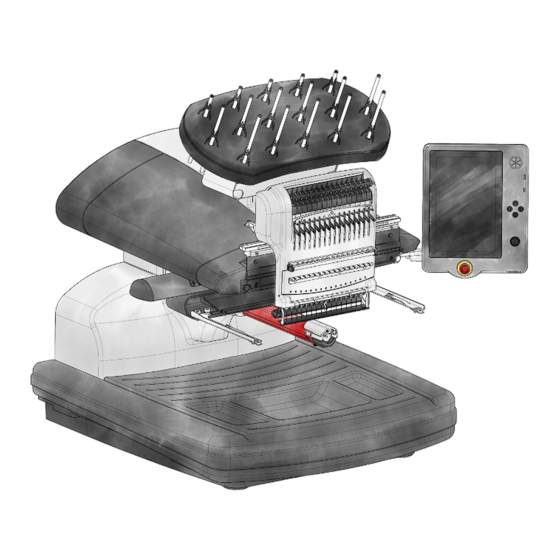
4. Machine Overview & Setup 1. Thread Tree 2. Thread Feed Rollers 3. Touchscreen Control Panel 4. Needle Case 5. Left Side Cover 6. Right Side Cover 7. Hoop Arms 8. Lower Arm 9. Ethernet Inlet (On Back) 10. Power Inlet (On Back) -
Page 14: Cart Assembly
4.1. Cart Assembly The cart consists of the items assembled as shown. Item Quantity Description Image Left Cart Leg Assembly Right Cart Leg Assembly Cart Base Support Cart Rear Support M6 x 1.0 x 12mm Button Head Screw M6 Flat Washer Cart Shelf Locator M6 Split Lock Washer... - Page 15 Stage 1 - Attaching the Base Support 1. Place items A and B (Cart Leg Assemblies) on the floor with the Casters facing up. The Casters with the brake face the front of the Cart. 2. Assemble Item C (Base Support) into the cutouts (see red highlights) located on each side of both Cart Legs, Items A and B, as shown.
- Page 16 Stage 3 - Installing the Machine Locators 1. Install items J, I, and F (M6 x 16mm Screw, M6 Lock Washer, and M6 Washer) from the bottom side of item G (Cart Shelf) as shown. 2. Install item H (Machine Locator) onto item J (Screw) from the top side of item G (Cart Shelf) as shown.
- Page 17 Note: Lift up item G (Cart Shelf) slightly to align item E (Screw) with the threaded inserts in the Cart Legs (items A and B). Assemble loosely, do not tighten. 3. Install (2 each) items E and F (M6 x 12mm Screw and M6 Washer) at locations shown towards the back side of the Cart.
-
Page 18: Installing & Adjusting The Screen
4.2. Installing & Adjusting the Screen Installing the Touchscreen 1. Locate the box containing the Touchscreen Assembly and X-Beam End Caps. The box is labeled with the following: 2. Attach the Touchscreen Assembly. a. Using the two screws and two lock Washers that came with the Touchscreen Assembly, attach the Touchscreen Assembly as shown in the image using a 5mm hex wrench (provided in the Machine Operator’s Kit). - Page 19 If present, the protective film can be removed from the screen after installation. Adjusting the Touchscreen Angle 1. Locate the tightening knob on the back of the touchscreen assembly. 2. Loosen the knob by turning it counterclockwise. 3. Tilt the touchscreen to the desired angle. 4.
-
Page 20: Powering Up The Machine
4.3. Powering Up the Machine Connecting the Power Cable 1. Locate the power cable you will be using with your machine. 2. Locate the power cable plug in the rear of the machine. 3. Make sure the machine power switch is in the OFF position. Plug the power cable into the inlet. 4. - Page 21 The screen will power up and the machine will continue through a series of initializing movements to find the hoop arm home position, needle at head up, and needle case on a needle. Once this is complete, a connection should fully establish between the machine and the screen.
-
Page 22: Threading The Machine
5. Threading the Machine... -
Page 23: Upper Threading
5.1. Upper Threading The proper thread path from the cone of thread to the eye of the needle is critical in the operation of the machine. Ensuring that the thread moves along the appropriate route will help prevent thread breaks as well as increase efficiency and sew quality. - Page 24 Changing a cone of thread does not require rethreading the entire thread path. If thread is already in the system, the fastest and easiest way to change a cone of thread is to remove the old cone but leave a good length of the old thread on the machine.
- Page 25 6. When finished, line up the thread under the pinch roller and press the pinch roller back down. 7. If desired, the thread can then be held by the retaining spring in front of the lower thread guide or held in place using the grabber. With your hands out of the way, tap the Grabber In / Grabber In button to close the grabber and move the thread into the holder behind the needles.
- Page 26 1. To start a new cone of thread, push the plastic thread tubes up from behind the thread tree. Place the cone of thread on the thread seat. The thread tube should extend ½ to 1 inch above the cone. Neglecting to extend the tube ½...
- Page 27 4. Pull the thread from the hole and place it under the pinch roller. Bring the thread down through the upper thread guide. 5. Pull the thread down to the middle thread guide. Of the three holes, push the thread from the top through the back right hole.
- Page 28 9. Press the thread into the felt restraint and feed it down through the lower thread guide. 10. Thread the needle from front to back. Cutting the end of the thread may allow it to more easily pass through the eye. 11.
- Page 29 Tap the Grabber Out button to open the grabber again.
-
Page 30: Bobbin Threading & Tensioning
5.2. Bobbin Threading & Tensioning The proper bobbin tension and installation also play an integral role in the quality and efficiency of an embroidery sew-out. What Type of Bobbin? For the best results with your machine, use Style L continuous polyester filament bobbins. Removing the Bobbin Case Warning!! ... - Page 31 Cleaning the Bobbin Case You should clean under the tension spring of your machine bobbin case every time you change the bobbin. Lint and bobbin wax can build up under the spring, and this can affect bobbin tension. This, in turn, will impact sew quality (loose bobbin, bobbin showing on front side of sew out, thread breaks, false thread breaks).
- Page 32 Inserting a New Bobbin in the Bobbin Case & Checking the Tension 1. Hold the bobbin case with the front facing down and the open end facing up.
- Page 33 2. Hold the new bobbin with the thread coming over the top and to the right in a clockwise fashion. It should look like a number nine (9). 3. Without flipping the bobbin, drop it into the bobbin case. 4. Route the thread through the thin slot opening and under the tension spring but stop before threading through the pigtail.
- Page 34 Using the Gauge Step 3 Step 4 Step 5 1. Clean and thread the bobbin case as you normally would. 2. Pull the thread through the tension spring, but do not pull the thread through the pigtail. 3. Insert the threaded bobbin case into the tension gauge with the extended portion of the latch falling into the guide as shown in red.
- Page 35 Adjusting Bobbin Tension 1. To adjust the tension, access the adjustment screw (the larger of the two) on the tension spring from the recessed corner of the gauge. 2. Using a small flat-blade screwdriver, turn the adjustment screw in small increments between testing. Small rotations can make large adjustments to the tension.
- Page 36 Inserting the Bobbin Case Warning!! Never attempt to remove or insert the bobbin while the machine is in operation. 1. Insert the bobbin and case in the machine with the pigtail facing up. Push on the bobbin case until it snaps into place.
-
Page 37: Sewing A Design
6. Sewing a Design Here is a general checklist for sewing a design. Load A Design · Set the Color Sequence · Select the Hoop · Set the Speed · Adjust Acti-Feed Settings for Fabric · Hoop and Product · Load Hooped Product onto the Machine ·... -
Page 38: Main Screen
7. Main Screen View Window The largest portion of the screen is devoted to a preview of the design in the selected hoop. This is meant to give the user an understanding of placement within the hoop and color selection. Within the View Window, you can Pan (Move) the view ·... - Page 39 The status bar will change to a progress bar as a design is sewn. It will fill in from flat to dimensional as it finishes sewing. Machine Status The status bar will also change colors depending on the machine's state. Additional information may appear as needed.
- Page 40 Return to Origin If not at design origin (start of design before any machine movements have occurred), the Load Design button will be swapped for the Return to Origin button. This button will return the machine to the very start of the design.
- Page 41 Actual Speed The actual speed is displayed below the set maximum speed. Acti-Feed Acti-Feed affects the amount of thread fed to the material being embroidered. While much of Acti-Feed is automated based on sensor feedback, giving Acti-Feed guidelines such as a minimum can help create higher-quality sewouts.
- Page 42 The Acti-Feed Minimum is displayed as the lower set line in the Feed Chart. Maximum The Acti-Feed Maximum sets an upper limit for the Acti-Feed. It allows the machine to adjust the amount of thread fed as needed, but it will not allow feeding more than the specified amount. It is uncommon to need to limit the maximum for the Acti-Feed.
- Page 43 Move to Trim · Tapping this will bring up a scrollable area with design segments previewed. These segments are divided by trims. Select the segment to move to and confirm to move through the design to the desired trim command/start of segment. Move to Color ·...
- Page 44 This is helpful when changing needles or capturing threads in the trap behind the needles. Presser Foot Adjustment This will bring the needle to its bottom-most rotation for a better view of the presser foot at this location. This is used for adjusting the presser foot height against the material. Maintenance &...
- Page 45 Do not confuse this button with the Emergency Stop button. The machine can still start if there is a machine fault somewhere. The stop/start button does not disconnect power from the motors or internal components. Emergency Stop Button The emergency stop button breaks the electrical circuit to all of the motors to prevent its operation. Direction Buttons On the main screen and the transform screen, the position of the hoop on the machine can be changed with these buttons.
-
Page 46: View Window
7.1. View Window The view window displays much information about the following. Design Display The currently loaded design is displayed in the view window. The design display can show Stitch Progress · Before starting, the design is displayed in 3D. After the design has started sewing, unsewn portions appear in 2D while sewn portions appear in 3D. - Page 47 Presets Preset swatches are stored background color values for later use. Show / Hide Options Graphic additions to the view window that can be toggled on or off depending on your preferences. These include: Colors from Design · This displays the colors of the design as saved in the design file rather than the colors assigned in the color sequence.
- Page 48 Zoom Bar The vertical bar on the left side of the window functions as a zoom area. Dragging up or down on this bar changes the zoom level. · Note! The view will follow the current stitch while zoomed in and sewing. Move X/Y &...
-
Page 49: Loading A Design
8. Loading a Design Your embroidery machine can hold a large number of designs in the touchscreen panel. Designs can also be loaded from USB flash drives or from local storage. Supported File Types Your embroidery machine will support the following embroidery design file types: OFM - version 9 and later ·... - Page 50 Favorites Favorites is a collection of designs that have been marked as a favorite. Any design stored locally on the touchscreen module can be marked as a favorite. This will allow it to show in these designs to be quickly referenced from this screen. Favorite designs are not moved from their original locations.
- Page 51 Location Contents The contents of the current folder/directory/source will be displayed in the main portion of this screen. Tapping on a folder will enter the folder/directory. § Tapping on a design file will bring up the Design Preview window. § File / Folder Management Functions for managing folders are located at the bottom of the screen. ...
- Page 52 Design file management icons are located on the right side of the window. This includes the following. Favorite - On locally stored files only. Tapping this button fills the icon and marks the design as a favorite. This will create a link in the Favorites location and make it visible from that location.
- Page 53 Confirm to Load the Design...
-
Page 54: Color Sequence
9. Color Sequence The color sequence screen is where you can do the following. Set the thread colors on the thread tree. · Manually or automatically needles, interrupts, or effects in a color sequence. · Apply interrupts or effects to the color sequence. ·... - Page 55 Colorize the Thread Tree To access the screen to colorize the thread tree, either Double-tap on a thread cone on the thread tree display · Tap on the Colorize Thread Tree button · To assign a thread to a needle 1.
- Page 56 Thinner 3D - adapts the Acti-Feed for use with thinner 3D embroidery foam - § typically around 2mm Thicker 3D - adapts the Acti-Feed for use with thicker 3D embroidery foam - § typically around 3mm Looping - adapts the Acti-Feed for use with thicker thread and intentionally §...
- Page 57 Colors from Design Off - If this view option is OFF, the selected color block in the view window will update to the newly assigned color. 3. Continue by selecting the next color block to change and repeating the first two steps. 4.
- Page 58 After an Appliqué command has stopped the machine, starting the machine will move § the hoop back into place and continue sewing the design. Pause - Placing this command between color blocks will cause the machine to stop and wait to be restarted, but it will not move the hoop forward. This command is often placed in designs larger than a single bobbin can sew as a §...
- Page 59 Effects are displayed as an overlay to a color block. Select the color block to which the effect is applied. Tap to select the trash button below the color sequence. Commands will be removed from the sequence entirely. Effects will be removed from the color block, but the color block will remain. To remove all commands and effects from the color sequence, Tap on the Reset Color Sequence button below the color sequence.
-
Page 60: Colorize Thread Tree
9.1. Colorize Thread Tree This screen shows the same thread tree display as on the previous screen. What needles are changed on this screen are reflected on the Color Sequence screen. Thread Charts List On the left side of the screen, the thread charts are listed. This list can be limited using the following tools. Search - Try adding the Manufacturer, Product Line, or even partial words in the search field to ·... - Page 61 Select another cone/needle to change or tap the confirm button to exit to the Color Sequence screen. Additional Functions On the bottom of the screen is the grabber function. It exists on this screen for easier access if changing cones of thread on the machine. Grabber In / Grabber Out ·...
-
Page 62: Thread Chart Preferences
9.2. Thread Chart Preferences This screen allows you to customize the number of charts visible on the screen for colonizing the thread tree. The field at the top of the screen allows you to search for a specific chart. Search - Try adding the Manufacturer, Product Line, or even partial words in the search field to ·... -
Page 63: Hoop Selection
10. Hoop Selection Selecting the same hoop in the software that is installed on the machine is critical for accurate placement and safety. Warning!! Selecting a different hoop than what is currently installed on the machine can potentially cause damage to the machine or yourself. - Page 64 Hoop List The hoop list displays the currently visible hoops and gives the hoop rough dimensions. Information Hoop dimensions listed may vary between manufacturers. In this list, dimensions are listed WIDTH x HEIGHT. To select a hoop, 1. Tap on the desired hoop. Tap on the confirm button.
- Page 65 Choosing a Hoop Shape Each hoop shape has benefits and drawbacks. Hoop Shape Benefit Drawback Even tension across the fabric. Limited number of sizes. Larger Traditional Round Great hoop for most left-chest hoops must be used for square- designs. shaped designs. Tension is often tighter in the Traditional Square Larger sew fields.
- Page 66 As they rarely provide the same hold on the materials as a traditional hoop, these hoops tend to be reserved for more specialized applications.
-
Page 67: Machine Speed
11. Machine Speed This reflects the maximum speed the machine will run. The machine may automatically slow for longer stitch movements in X, Y, and also Z. Longer stitches, as well as higher thread feed values, may affect speed. Changing Machine Speed The machine speed may be altered by clicking or tapping the plus or minus button on either side of the speed setting. - Page 68 Symptoms From Sewing Too Fast Sewing at too high of a speed can result in a few undesirable outcomes. These would include: Thread breaks · Bobbin pulling to the top · Poor registration of designs (design details or outlines don’t line up) ·...
-
Page 69: Acti-Feed
12. Acti-Feed Acti-Feed affects the amount of thread fed to the material being embroidered. While much of Acti-Feed is automated based on sensor feedback, giving Acti-Feed guidelines such as a minimum can help create higher-quality sewouts. Feed Chart This chart helps monitor the feed of thread to the product. It displays the following: Feed - This is the amount of thread being fed to account for the detected material thickness. - Page 70 Maximum The Acti-Feed Maximum sets an upper limit for the Acti-Feed. It allows the machine to adjust the amount of thread fed as needed, but it will not allow feeding more than the specified amount. It is uncommon to need to limit the maximum for the Acti-Feed.
- Page 71 Appropriate Acti-Feed Settings Finding the perfect settings or limits for your acti-feed is not always necessary, but it can improve sew quality and machine performance. Sew quality and thread breaks are indicators of appropriate or inappropriate thread feed. Those symptoms are listed in the sections below.
- Page 72 Satin stitches - Not enough bobbin is showing on the back of the design. · Fill stitches - You are encountering thread breaks, and the stitches in the design are looping. · False Bobbin Breaks - When the software falsely detects bobbin breaks that are not truly broken ·...
-
Page 73: Transform
13. Transform The transform screen allows for the movement or placement and rotation of designs. View Window in the Transform Screen Move X/Y & Rotate When in the transform screen, the view window takes on different functions. These functions can be changed back using the switch on the right side of the screen. - Page 74 45° Counterclockwise or 45° Clockwise · 90° Counterclockwise or 90° Clockwise · 180° - often used with cap designs · Flip the design vertically · Flip the design horizontally · Move/Rotate By The right side of the screen provides an area for more precision in movement and rotation. Tap into a field to specify an amount and then use the following corresponding buttons to execute the movement or rotation.
- Page 75 Machine Operations To make positioning in the hoop a bit easier, some machine functions were copied to this screen to help with visibility. They include the following. Change to Needle (Move Needle case) · Tapping this brings up a window displaying the thread tree / needle assignments. Selecting the desired needle number and confirming will move the needle case to that needle.
- Page 76 Confirm the position of the second point by tapping the confirm second point button. Once both points are confirmed, the design is rotated to match the line created by the two points and the positioning buttons become available. Tapping any one of the following buttons will differently position the design in relation to the line created by the two confirmed points.
-
Page 77: Presser Foot Adjustment
14. Presser Foot Adjustment The machine has an adjustable presser foot that can be set from 0.5mm to 3.5mm above the needle plate. The presser foot height should be changed when the thickness of the material you are sewing changes dramatically. To adjust the presser foot height, the software must be open, and your machine must be on and communicating with it. - Page 78 Setting the Presser Foot for Different Materials The presser foot will need to be adjusted whenever you drastically change the thickness of the material that you are sewing on. For example, if you sew a sweatshirt and then sew a T-shirt, the presser foot would need to be adjusted.
-
Page 79: Trace Design
15. Trace Design Tracing a design is an easy way to check placement on the hooped product. Trace 1. Tap on the Trace button in the view window. 2. Optional - Select the trace shape Traces a polygon created from the outermost points of the design Traces a rectangle of the farthest edges of the design. - Page 80 Top Center · Top Right Corner · Middle Left · Middle Center (Usually Design Origin) · Middle Right · Bottom Left Corner · Bottom Center · Bottom Right Corner · Additional Functions Grabber In / Grabber Out Closes and opens the grabber. ·...
-
Page 81: Settings
16. Settings The Settings page is full of settings for the touchscreen and software with access to additional settings for the machine below. Machine Name · Edit the machine name by tapping on the edit button or within the field. This provides a customizable machine name to make it easier to tell multiple machines apart. - Page 82 Touchscreen Brightness · This slider adjusts the brightness of the screen. Screen Saver Delay · This adjusts the delay for the screen saver. Setting this to zero disables the screen saver. Additional Settings Design Filter · Adjust settings related to the stitches and trims within the design. Advanced Acti-Feed ...
-
Page 83: Network Connection
16.1. Network Connection Connection Setup Tapping on Connection Setup takes you to the Network Selection screen. On this screen, you can select the connection type. Wireless - choose from the list of available networks discovered below. · Rescan - If needed, a scan can be requested and a new list generated. If a password is required, a password request and keyboard will appear. -
Page 84: Design Filter
16.2. Design Filter Stitch Filters These filters add or remove needle penetrations along existing lines based on the settings below. Maximum Stitch Length · If a stitch exceeds this amount, a needle penetration will be added to evenly divide the stitch into lengths that fall below this threshold. - Page 85 Some embroidery designs with longer stitches may contain a jump between the needle penetrations creating the stitch. If the Count to Convert number is less than or equal to the number of jumps between these penetrations, the stitches themselves will become trims. This creates an odd machine behavior where there is only a single needle penetration, followed by a trim.
- Page 86 Setting this value to something close to that may prevent thread breaks from continually trying to sew satin stitches smaller than the needle being used. Use Custom Table The compensation settings above are only used if Custom Table is disabled. If Custom Table is enabled, a custom table is used.
-
Page 87: Pull Compensation
16.2.1. Pull Compensation Selecting a Compensation Table 1. Tap the expand-down button to open the drop-down. Tapping within the field will allow the name of any custom table to be edited. Wide-Angle Driver offsets will be added to the global compensation values when using any frame that utilized the wide-angle driver. - Page 88 Caution! Altering these values can produce a subtle shift or a huge difference in the look of the satin stitches produced by your machine. Keeping notes of changes made and used in this screen is advised.
-
Page 89: Machine Preferences
16.3. Machine Preferences All Thread Detection · When disabled, no upper or lower thread breaks are detected. Disabling automatically disables Bobbin Thread Detection. When enabled, upper thread breaks are detected. Enabling DOES NOT automatically reenable Bobbin Thread Detection. Thread break detection can be affected by poor hooping technique, unsuitable Acti-Feed settings, and inappropriate presser foot adjustment. - Page 90 Force Design Return to Origin · When disabled, the hoop position may remain at the last stitch of the design. Many designs already end with a return to origin command. When enabled, the hoop position will return to design origin whether or not the design file ends with that command.
-
Page 91: Advanced Acti-Feed Calibration
16.4. Advanced Acti-Feed Calibration This section of Machine Preferences will alter the behavior of Acti-Feed. This will cause thread breaks to be detected more or less frequently and make tighter or looser embroidered stitches. Caution! Changing these settings will alter the way the thread is fed to the cloth and the accuracy of thread ... - Page 92 Minimum Offset: This offset is applied to the minimum Acti-Feed setting. This is meant to account for the thickness of the foam used when creating 3D embroidery. This number should be about or just under the thickness of the foam in tenths of a millimeter.
- Page 93 Information Upon closing this screen, you will be cautioned about making changes to these settings as changes here can greatly impact the performance of the machine and the quality of the embroidery.
-
Page 94: Software Updates
16.5. Software Updates The Software Updates screen will walk you through updating the software when needed. The developers are always working to improve the products, so updates with enhancements to performance and features may be made available at any time. Notifications (Internet Connection Required) ·... -
Page 95: Maintenance
17. Maintenance Maintenance Timers The top portion of the screen is devoted to the maintenance timers. These count down at specific intervals and prompt you to perform the required maintenance on time or after a specified number of stitches. Each timer counts down both a specific amount of time and a set number of stitches. When either interval is reached, the maintenance will be due and the step-through button will pulse yellow. - Page 96 Go to the Next Step · Cancel - Exit without completing the step-through. · Completed - Exit and reset the timer. · In Spec - the X-cable tension is within the spec - continue to the next step · Out of Spec - the X-cable tension is out of spec - continue to the next step for adjustment ·...
- Page 97 Tapping this will open the status log and display a history of actions along with timestamps.
-
Page 98: Head Timing
17.1. Head Timing The Head Timing screen deals with the Z-rotation of the machine. Warning!! Tapping almost any button in this screen will make the machine move the needle. Be careful and stay clear of the needle. Exiting this screen will also cause the machine to return to the Head Up position. Move To a Specified Degree 1. - Page 99 Rotate plus 10° · Rotate plus 5° · Rotate plus 1° · Rotate plus 0.1° · · Rotate minus 20° · Rotate minus 10° · Rotate minus 5° · Rotate minus 1° · Rotate minus 0.1° · Current Z Position This displays the current Z position of the machine.
-
Page 100: Sensors
17.2. Sensors The sensors screen shows the status of the sensors. The onscreen representation of the LEDs corresponds to the state of the LEDs on the board. The sensors show as Active · Inactive · The groups indicate which sensor is being shown. X-Axis ·... - Page 101 Inactive - Z Position is between 0° and 180° § Safe - Provides information to the machine related to color change operations. Active - Z Position is at Head Up (27°) § Inactive - Z Position is not at Head Up §...
-
Page 102: Needle Case Calibration
17.3. Needle Case Calibration The calibration tab is used for calibrating the color change table. Essentially this is the information that keeps all of the machine needles in the center of the hole in the needle plate. If this calibration is off, it can cause thread breaks and needle breaks. - Page 103 Select the Needle to Move to · Move One Needle Down · Needle Case Adjustments The needle case calibration table can be adjusted and tested using the following buttons on the lower portion of the screen. Shift Needle Case Left - also adjusts the table on the machine's board ·...
-
Page 104: Steppers
17.4. Steppers Used mainly by technicians, the Steppers Screen allows access to certain motor functions. Color Change Home · Returns the Needle Case to the home position. This will move to a mechanical limit and then back to needle 1 Needle + ·... - Page 105 NPT Sensor is enabled NPT Sensor is disabled Grabber Home · Moves the grabber out (Home) · Moves the grabber in. · Start Test / End Test Cycles the grabber in and out. Home · The grabber is in the home position. The grabber is not in the home position.
- Page 106 The thread feed gear is not in the home position. Feeder Profile · Use the Feeder Profile button to rotate the thread feed motor one full revolution to analyze the tooth profile of the drive gear and populate the fields below the button. Feeder Home Adjust ·...
-
Page 107: Hooping
18. Hooping Hooping the fabric or garment securely is important to the quality of the embroidery. This section will walk you through the adjustment of the hoop tension as well as the hooping process. Adjusting the Hoop Tension You will need to adjust the tension of the hoop any time you change to a drastically different material. For example, changing from a T-shirt to a sweatshirt would require a change in hoop tension. - Page 108 10. Now, without loosening the screw, remove the hoop from the garment. 11. Tighten the adjustment screw a turn or two more. 12. The outer hoop is now adjusted. Note: The appropriate tightness of a hoop can be tested by tapping rapidly with moderate pressure on ...
- Page 109 7. Using the hoop arms as a guide, make sure that the hoop is level with the garment. This will help prevent sewing a design crookedly on a product. 8. Press the hoop down and into place. Take care to press on the ring rather than on the arms. Pressing on the arms can bend the hoop out of shape or break it.
- Page 110 10. Check the back of the hooped piece. Make sure that there are no wrinkles or other parts of the garment lodged in the hoop. 11. As a final step, check the hoop for placement accuracy and straightness. Hooping Tips Round hoops give the most even tension of all the hoop shapes.
-
Page 111: Loading A Hoop Onto The Machine
19. Loading a Hoop onto the Machine 1. Install a hoop by sliding the side brackets of the hoop underneath the spring clips on the support arms. Make sure that the slotted bracket is to the right as you are facing the machine. -
Page 112: Needles
20. Needles... -
Page 113: Replacing A Needle
20.1. Replacing A Needle Sew conditions and material properties will affect the life of a needle, but eventually, needles will need to be changed. 1. Make sure the safety grabber blade is in the back position before changing a needle. If it is not, press the Adjustment and Center keys on the machine keypad to move the grabber back. -
Page 114: Needle Types
20.2. Needle Types Embroidery quality can be greatly affected by your choice of needles. You will need to find what works best with your applications. The following information should help. Choosing a Needle Your machine utilizes DBxK5 needles. Among other things, this means that they are industrial needles with larger eyes. - Page 115 Largest of the more common needles. Often Larger holes can damage finer materials and 80/12 used caps with buckram backing or cotton smaller design details. duct jackets to help alleviate thread breaks. Larger holes can damage finer materials and Used with some specialty and metallic 90/14 smaller design details.
-
Page 116: Thread Types
21. Thread Types Thread comes in many styles, weights, and compositions. Understanding the differences can help determine the appropriate thread for the job. Information Manufacturers and suppliers often have fact sheets with sewing tips, design settings, and needle recommendations on their websites. This is very useful in learning to use a variety of thread types. Thread Content Thread comes in a few compositions. - Page 117 Requires lighter densities and longer stitch lengths · Usually requires slower sew speeds and larger needles · Wool/Acrylic Blend and Wool/Cotton Usually a heavier thread, these threads can be used for a more natural or hand look. Unique look · Can be more problematic to sew with ·...
-
Page 118: Stabilizers
22. Stabilizers Appropriate stabilizer is essential for embroidering most fabrics. Without stabilizer, fabrics can slip even when they are hooped tightly. Using the proper stabilizer is directly linked to the production of consistently high-quality embroidery. It is important to understand that many different embroiderers with identical criteria may choose completely different stabilizer and topping formulas and still achieve successful embroidery results. - Page 119 Tear-away Tear-away stabilizer is a non-woven material that tears easily in any direction and can be easily removed after embroidery. Tear-away is extremely simple and fast to use, but the uses are limited because it offers little support to unstable fabrics. Some examples of fabrics suitable for tear away are cotton sheeting, heavy woven dress shirts, denim, terry cloth, and hats.
- Page 120 Embroidery on T-Shirt Cut-away stabilizer provides needed stability to the thin knit of a T-shirt. The embroidery holds the shape of the design. Tear-away stabilizer does not hold up to the embroidery. The stitching is allowed to pull in and the borders do not line up.
- Page 121 Tear-away stabilizer allows the T-shirt to pull and pucker as the design is sewn. Stabilizer Weights Stabilizer comes in different thicknesses. Many times, you can ask for sample packets from suppliers to find what will work best with your application. Heavier stabilizers tend to offer more support.
-
Page 122: Attaching & Adjusting Hoop Arms
23. Attaching & Adjusting Hoop Arms Depending on the hoop you plan on using, the hoop support arms on the machine will need to be in the inner position, outer position, or removed completely if using a clamp or the wide-angle driver. This section will walk you through attaching and removing the support arms properly as well as adjusting the spring clips. - Page 123 Removing the Hoop Support Arms 1. Use a 6mm hex wrench to loosen each of the two thumb screws attaching each arm to the x-carriage. 2. Using your fingers, fully loosen the thumb screws. 3. Remove the support arms from the x-carriage. Adjusting the Spring Clips When you have a hoop installed, you should make sure both spring clips are attached securely to the arms.
-
Page 124: Installing The Wide-Angle Driver
24. Installing the Wide-Angle Driver Cap frames and micro clamps utilize the Wide-Angle Driver. The Wide-Angle Driver consists of two pieces. The cap frame driver ring · The lower arm bracket · You must ALWAYS select the proper frame/hoop in the software when sewing with the Wide-Angle Driver. Failure to do so may result in damage to your equipment! Wide-Angle Driver Installation 1. - Page 125 Warning!! Failure to remove the hoop arms will result in the wide-angle driver colliding with the arms during sewing. 5. Remove the hook guard. a. Loosen the thumb screw securing the hook guard and slide it away from the machine. b.
- Page 126 10. A few drops of sewing machine oil should be applied to the lower support shaft prior to the initial installation of the driver ring assembly. This oil should be applied every three months on later installations. 11. Slide the red driver assembly onto the lower arm and support shaft. This may be easier if the grabber bar of the machine is closed.
- Page 127 Information The red driver ring should slide easily over the lower arm of the machine and should allow for a business card or two to fit between the ring and the lower arm. The space should be enough for the card(s), but no more.
- Page 128 4. Loosen the knobs of the lower shaft support. Then, slide the lower support shaft out of the t-channel and off the machine. 5. Reattach the hook guard by sliding it back into place and tightening the thumb screw. 6. The wide-angle driver is now removed. Hoop arms can be reattached to sew with flat hoops.
-
Page 129: Adjusting The Wide-Angle Driver
24.1. Adjusting the Wide-Angle Driver This procedure may need to be performed if the Wide-Angle Driver was purchased separately from your machine, the driver has been dropped or mishandled, if the initial installation of the driver shows the adjustment to be off, or if prompted by technical support. The Wide-Angle Driver may need to be adjusted to custom-fit each machine. - Page 130 Adjustment Procedure 1. Begin by loosening the two bearing block hex screws and the two interface bracket screws using the 4mm hex screwdriver. Install the Wide-Angle Driver on your machine. 3. Position the driver so that the bearing block is aligned to the front of the support shaft and the driver ring is centered with the hole in the needle plate.
- Page 131 4. Place a business card of medium to heavy stock (or equivalent) between the needle plate and the driver ring. This will act as a spacer. The ring should just rest on the card. 5. While making sure the edges of the two black brackets are aligned, tighten one of the upper screws. 6.
-
Page 132: Maintaining The Wide-Angle Driver
24.2. Maintaining the Wide-Angle Driver Approximately once per year, the red wide-angle driver will need to be cleaned and greased. The following steps will walk you through the procedure. 1. Remove the driver cylinder from the machine and lay it upside down on a flat surface. 2. -
Page 133: Sewing Caps
25. Sewing Caps Sewing caps will require a little more setup than sewing a flat product. For sewing caps, you will need to do the following. 1. Select the appropriate hoop in the application. Install the Wide-Angle Driver. This may need adjusting the first time. Hoop a cap. -
Page 134: Hooping A Cap
25.1. Hooping A Cap The process for hooping a cap on the Wide Angle Cap Frame (WACF) is the same for almost any type of cap or visor you are hooping. You will want to have the cap gauge installed on a sturdy surface to start. Preparing the Cap Preparing the cap before it is hooped will help the sew quality and ease the hooping process. - Page 135 4. If the cap has a braid, move it around the cap to the inside and under the brim. Hooping the Cap To hoop the cap, 1. Slide the cap frame onto the cap gauge. Make sure the locating tab on the cap gauge fits into the cap frame notch and the cap frame slips firmly under the two roller clips.
- Page 136 Some people find it easier to use the binder clips to hold the stabilizer while they are hooping the cap. The downside to this technique is that you have to remove the clips from inside the cap when you are done hooping. That isn’t always easy. Clipping the stabilizer before hooping the cap is completely optional.
- Page 137 7. Pull the side of the sweatband toward the cap frame and down. Smooth any bunching of the cap sides or sweatband. You may eventually need to fold the sweatband a bit to avoid the latching hook. But this will help with the placement of the cap on the frame. As you do this, watch the stabilizer to ensure it is still in 8.
- Page 138 11. Hook the latch on the strap into the hook on the latch post. You may need to fold or adjust the sweatband of the cap slightly to accommodate the hook and latch. At this point, you want to hook the latch, but not close the latch.
- Page 139 Tighten the wing nuts while holding the strap tight against the cap. 13. Smooth the lower part of the cap while snapping the buckle closed. The buckle should be tight. 14. If clips were used to secure the stabilizer while hooping, remove them now. 15.
- Page 140 Information Text 17. You may now remove the cap frame from the gauge. To do this, place the palms of your hands on the gauge and place your fingers on the frame. Pull your fingers toward your palms until the cap frame released from the gauge. Inspect the hooping.
-
Page 141: Loading A Hooped Cap
25.2. Loading a Hooped Cap To load a hooped cap onto the installed wide-angle driver, use the following steps. 1. Rotate the hooped cap 90° to allow the bill to pass under the needle case. 2. Rotate the bill back up so that it is behind the needle case and the location tab on the driver aligns with the notch in the frame. - Page 142 Removing a Hooped Cap To remove a hooped cap from the installed Wide-Angle Driver, use the following steps. 1. Press the three locking clamps on the driver while gently pulling back on the frame. 2. This will allow the frame to release and be pulled free from the driver. 3.
-
Page 143: Sew Settings For Caps
25.3. Sew Settings For Caps The settings in the application will need to be adjusted for better quality on a cap. Be sure to address the following. Design Orientation To be oriented appropriately for a cap, the design usually needs to be rotated 180° in the software. For assistance on this, review the Transform section of this document. - Page 144 If the needle is not at the presser foot adjustment point, the presser foot will not appear to move. Even if the needle is at the adjustment point, it may be difficult to see a change in the presser foot. The material of the cap is pressing up against it and you may not see it lift off the material.
- Page 145 Marking this measurement on the cap with masking tape or tailor’s chalk works well. Use the physical up or down arrow to move the hoop into position. As you use these buttons, the machine’s laser will illuminate the placement. Centering Horizontally With the cap frame loaded on the machine, use the physical left or right arrow buttons to center the cap horizontally.
- Page 146 Watch the Hoop Limits Depending on the structure of the cap, you will be able to sew within varying distances from the hoop limits. Softer, thinner, and more pliable materials will allow you to sew closer to the limit. Tougher and less flexible materials may cause the fabric to ramp up at the teeth causing flagging, needle deflection, and thread or needle breaks.
Need help?
Do you have a question about the E 16 PRO and is the answer not in the manual?
Questions and answers
where does the piece of foam go under the right removeable cover?
how do i back up on the stitches