Kyocera TASKalfa 7002i Service Manual
Hide thumbs
Also See for TASKalfa 7002i:
- Operation manual (645 pages) ,
- First steps quick manual (36 pages) ,
- Safety manual (2 pages)

Related Manuals for Kyocera TASKalfa 7002i


Summary of Contents for Kyocera TASKalfa 7002i
- Page 1 TASKalfa 7002i TASKalfa 8002i TASKalfa 9002i PF-730(B)/PF-740(B) PF-7120/PF-7130 DF-7110 MT-730(B) BF-730 PH-7A/PH-7C/PH-7D FAX System 12 SERVICE MANUAL Published in December 2021 Rev.5...
- Page 2 For the purpose of this service manual, products are identified by print speed. Product name Print speed 100 V 120 V 220-240 V Australia TASKalfa 9002i 90 ppm ○ ○ ○ TASKalfa 7002i 80 ppm ○ ○ ○ ○ TASKalfa 8002i 70 ppm ○ ○ ○ ○...
- Page 3 Revision history Revision Date Pages Revised contents 30 June 2017 Contents Correction: Warm-up Time Correction: Power source, Note 1-4,1-5 Correction: Operating System Correction: 4,000-Sheet Finisher: Space Required 2-2,2-3 Correction: Installation procedures Correction: Procedures 8 2-29,2-31 Correction: Procedures Letter→A4,B5 2-37 Added: 120 V: 70/80 ppm model 2-43 Correction: Setting procedures 2 2-44...
- Page 4 Revision Date Pages Revised contents 6-103 Deletion: U156 B/W 6-105,6-107 Correction: U161 Contents Belt Mode, Belt Mode 6-109 Added: U167 Setting: Correction 6-110 Correction: U169 CT Mode Note 6-118 Added: U204 Parallel Coin Vender,Note 6-119 Added: U206 Note 6-140 Added: U246 Shift Front HP / Shift Tail HP 6-151 Correction: U253 DBL(A3/Ledger)/DBL(B4) 6-177,6-178...
- Page 5 Revision Date Pages Revised contents 6-44,6-45 Added: U051 Initial setting 90ppm 6-48 to 6-50 Added: U053 Initial setting 90ppm 6-56 to 6-59,6- Deletion: Initial setting 70 ppm/ 80ppm 61,6-63 6-74 Added: U100 Initial setting 90ppm 6-76 to 6-80 Added: U106 Initial setting 90ppm 6-87 Added: U131 Initial setting 90ppm 6-96...
- Page 6 This page is intentionally left blank.
- Page 7 Safety precautions This booklet provides safety warnings and precautions for our service personnel to ensure the safety of their customers, their machines as well as themselves during maintenance activities. Service personnel are advised to read this booklet carefully to familiarize themselves with the warnings and precautions described here before engaging in maintenance activities.
- Page 8 Safety warnings and precautions Various symbols are used to protect our service personnel and customers from physical danger and to prevent damage to their property. These symbols are described below: DANGER: High risk of serious bodily injury or death may result from insufficient attention to or incorrect compliance with warning messages using this symbol.
- Page 9 1. Installation Precautions WARNING • Do not use a power supply with a voltage other than that specified. Avoid multiple connections to one outlet: they may cause fire or electric shock. When using an extension cable, always check that it is adequate for the rated current...................... •...
- Page 10 2. Precautions for Maintenance WARNING • Always remove the power plug from the wall outlet before starting machine disassembly....• Always follow the procedures for maintenance described in the service manual and other related brochures............................• Under no circumstances attempt to bypass or disable safety features including safety mechanisms and protective circuits.
- Page 11 • Do not remove the ozone filter, if any, from the copier except for routine replacement....... • Do not pull on the AC power cord or connector wires on high-voltage components when removing them; always hold the plug itself......................•...
- Page 12 This page is intentionally left blank.
- Page 13 2WA/2NJ/2RK CONTENTS Specifications 1-1 Specifications ........................... 1-1 (1) Common function ........................ 1-1 (2) Copy Functions........................1-4 (3) Printer Functions ......................... 1-5 (4) Scanner Functions....................... 1-6 (5) Document Processor ......................1-6 (6) Option ..........................1-7 (6-1) Side Feeder (500 sheets ×3)..................1-7 (6-2) Large Capacity Feeder (500sheets, 1,500sheets ×2) ..........
- Page 14 2WA/2NJ/2RK-1 2-1 Environment ..........................2-1 2-2 Installing the main unit ......................2-2 (1) Unpacking and checking bundled items ................2-4 (1-1) Machine........................2-4 (1-2) Take out of the machine unit ..................2-5 (1-3) Take out of fixed tape and cushioning material............2-7 (2) Notes on main unit transportation..................
- Page 15 2WA/2NJ/2RK-1 (9-1) In the case of main unit cassette (120V/220 to 240V models only) ......2-99 (9-2) In case of Paper Feeder (PF-730(B))..............2-111 (9-3) In case of Paper Feeder (PF-740(B))..............2-115 (9-4) In case of Side Paper Feeder (PF-7120) ............... 2-120 (10) In the case of side multi tray(PF-7130)................
- Page 16 2WA/2NJ/2RK (3-1) Paper feeder (PF-730(B))..................3-33 (3-2) Paper feeder (PF-740(B))..................3-35 (3-3) Paper feeder (PF-7120) ................... 3-37 (3-4) Paper feeder (PF-7130) ................... 3-38 (3-5) 4000-sheet Finisher (DF-7110) ................3-39 (3-6) Mailbox (MT-730(B)) ....................3-41 (3-7) Punch unit (PH-7)..................... 3-42 (3-8) Folding unit(BF-730)....................3-43 3-5 Mechanical construction ......................
- Page 17 2WA/2NJ/2RK (8-2) Tri-folding position adjustment for the folding unit..........3-111 Maintenance 4-1 Precautions for the maintenance ....................4-1 (1) Precautions.......................... 4-1 (2) Storage and handling of the drum ..................4-1 (3) Storage of the toner container ..................... 4-1 4-2 Maintenance parts ........................4-2 (1) Maintenance kits........................
- Page 18 2WA/2NJ/2RK (3) Side feeder (PF-7120) ....................... 4-66 (3-1) Detaching and reattaching the pickup pulley and paper feed roller ......4-66 (3-2) Detaching and reattaching the retard pulley............. 4-68 (4) Side Multi Feeder (PF-7130) ..................... 4-69 (4-1) Detaching and reattaching the forwarding pulley/paper feed pulley/ separation pulley ......................
- Page 19 2WA/2NJ/2RK (7-4) Detaching and reattaching the main high-voltage PWB......... 4-187 (8) Detaching and reattaching the IH PWB................4-193 (8-1) Detaching and reattaching the operation panel PWB ..........4-200 (9) Detaching and reattaching the PF main PWB and PF power source PWB..... 4-204 (10) Document processor .......................
- Page 20 2WA/2NJ/2RK (1) Isolate the place of image failure..................7-1 (2) Scanner Factors (when scanning from DP)................. 7-2 (2-1) Abnormal image ......................7-4 (2-2) Colored background ....................7-6 (2-3) Black or color spots appear on the image ..............7-8 (2-4) Blurred characters ...................... 7-9 (2-5) Original center and copy image center are mismatched ..........
- Page 21 2WA/2NJ/2RK (4-11) Blurred characters ....................7-55 (4-12) Offset........................7-56 (4-13) Fusing failure......................7-57 (4-14) Paper skew at the trailing edge ................7-57 (4-15) Uneven transfer......................7-58 (4-16) Blurred image ......................7-58 (4-17) Vertical white streaks or band .................. 7-59 (4-18) Vertical black streaks or band .................. 7-59 (5) ngine Factors (Image forming cause)................
- Page 22 2WA/2NJ/2RK (1-1) The login fails with other than the ID card.............. 7-494 (1-2) C0030: FAX PWB system error................7-494 (1-3) C0070: FAX PWB incompatible detection error ............. 7-495 (1-4) C0650: FAX image storage pair-check error............7-495 (1-5) C0830: FAX PWB flash program area checksum error.......... 7-496 (1-6) C0870: PC FAX Image data transmission error .............
- Page 23 2WA/2NJ/2RK (23) Data is not printed out due to the printer driver setting............ 7-577 (24) Data is not printed out due to the printer driver setting............ 7-577 (25) The printed image is partly missing ................. 7-578 (26) "Paper Mismatch Error" appears ..................7-578 7-8 Abnormal Noise ........................
- Page 24 2WA/2NJ/2RK (8-1) Connector position ....................8-58 (8-2) PWB photograph ...................... 8-58 (9) Operation panel main PWB ....................8-62 (9-1) Connector position ....................8-62 (9-2) PWB photograph ...................... 8-62 (10) IH PWB..........................8-68 (10-1) Connector position ....................8-68 (10-2) PWB photograph ...................... 8-68 (11) Fuser high-voltage PWB....................
- Page 25 2WA/2NJ/2RK (4) Cleaning the left registration cleaner ................. 9-11 Chart of image adjustment procedures ................9-12 9-5 Wiring diagram ........................9-15 (1) Engine PWB ........................9-15 (2) Laser Scanner ........................9-16 (3) Front PWB ......................... 9-17 (4) Fuser ..........................9-18 (5) Feed PWB (1)........................
- Page 26 2WA/2NJ/2RK This page is intentionally left blank.
- Page 27 2WA/2NJ/2RK-2 1 Specifications 1-1 Specifications (1) Common function Items Description Product name 70 ppm model / 80 ppm model/ 90 ppm model Type console Printing Method Electrophotography by semiconductor laser Paper Weight Cassette 60 to 256 g/m Multi Pur- 60 to 300 g/m pose Tray Paper type Cassette...
- Page 28 2WA/2NJ/2RK Items Description Output Tray Left lower 275 sheets (64 g/m Capacity tray 250 Sheets (80 g/m Left upper 110 sheets (64 g/m tray 100 Sheets (80 g/m Right tray 70 sheets (64 g/m , 80 g/m Image Write System Semiconductor laser and electrophotography Light source LED array...
- Page 29 2WA/2NJ/2RK-1 Items Description Space Required (W ×D) 39.97" × 32.37"/ 1,015 × 822 mm/ (Using multi purpose tray) Power source 100 V Specification Model (70ppm model): 100 V 50/60 Hz 15.0 A 100 V Specification Model (80ppm model): 100 V 50/60 Hz 15.0 A(IH)+5.0 A 120 V Specification Model: 120 V 60 Hz 16 A...
- Page 30 2WA/2NJ/2RK-2 (2) Copy Functions Items Description Copy Speed 70 ppm A4/Letter 70 sheets/min model A4-R/Letter-R 49 sheets/min A3/Ledger 35 sheets/min B4 / Legal 42 sheets/min 70 sheets/min B5-R 49 sheets/min A5-R 35 sheets/min 80 ppm A4/Letter 80 sheets/min model A4-R/Letter-R 56 sheets/min A3/Ledger 40 sheets/min...
- Page 31 2WA/2NJ/2RK-2 (3) Printer Functions Items Description Printing Speed 70 ppm model 12x18" 35 sheets/min 80 ppm model 12x18" 40 sheets/min 90 ppm model 12x18" 45 sheets/min Other than the above size, specifications are the same as those of Copy Speed. First Print Time (A4) 70 ppm model: 5.8 seconds or less 80 ppm model: 5.4 seconds or less...
- Page 32 2WA/2NJ/2RK-2 (4) Scanner Functions Items Description Resolution 600 dpi ×600 dpi, 400 dpi ×400 dpi, 200 dpi ×400 dpi, 300 dpi ×300 dpi, 200 dpi ×200 dpi, 200 dpi ×100 dpi File Format TIFF, JPEG, XPS, Open XPS, PDF (MMR/JPEG compression/High compres- sive PDF/OCR Text Recognition) Scanning 70 ppm model...
- Page 33 2WA/2NJ/2RK-1 (6) Option (6-1) Side Feeder (500 sheets ×3) Items Description Paper Supply Method Feed & reverse roller method (No. Sheets: 550 sheets(64 g/m²)x3 cassettes / 500(80g/m²)×3 cassettes) Paper Size A3, A4-R, A4, A5-R, B4, B5-R, B5, 216x340 mm, Ledger, Letter-R, Letter, Legal, Statement-R, 12x18", Oficio II, Folio, 8K, 16K-R, 16K Supported Paper Paper weight: 60 to 256 g/m²...
- Page 34 2WA/2NJ/2RK (6-4) 4,000-Sheet Finisher Items Description Number of Trays 3 tray Paper Size Tray A A3, B4, B5-R, 216×340 mm, Ledger, Legal, Executive, 12×18", Oficio II, Folio, 8K, (80 g/m (Non-Sta- 16K-R:1,500 sheets pling) A4-R, A4, B5, Letter-R, Letter, 16K: 4,000 sheets A5-R, B6-R, Statement-R: 500 sheets Tray B A3, A4-R, A4, A5-R, A6-R, B4, B5-R, B5, B6-R, 216x340 mm, Ledger, Letter-R, Let-...
- Page 35 2WA/2NJ/2RK (6-6) Mailbox (4,000 sheets finisher option) Items Specification Number of Trays 7 trays Paper Size(80 g/m²) A3, B4, Ledger, Legal, 8K: 50 sheets A4-R, A4, A5-R, B5-R, B5, 216x340 mm, Letter-R, Letter, Statement-R, Executive, Oficio II, Folio, 16K-R, 16K: 100 sheets Dimensions 20.08"...
- Page 36 2WA/2NJ/2RK (6-8) Banner Tray Items Description Max. number of sheets 10 sheets (Multi Purpose tray) Paper width 210 to 304.8 mm (8.26" to 12") Paper length Max. 1220.0 mm (48") Supported Paper Paper weight: 136 to 163 g/m² Media types: Heavy 2 Dimensions 9.85"...
- Page 37 2WA/2NJ/2RK (6-9) FAX System FAX function Items Description Compatibility Communication Line Subscriber telephone line Transmission Time Less than 3 seconds (33600 bps, JBIG, ITU-T A4-R #1 chart) Transmission Speed 33600/31200/28800/26400/24000/21600/19200/16800/14400/12000/ 9600/7200/4800/2400 bps Coding Scheme JBIG/MMR/MR/MH Error Correction Original Size Maximum width: 297 mm, maximum length: 1,600 mm Number of originals to auto Max.
- Page 38 2WA/2NJ/2RK Items Description Job Accounting Requires the input of a Login User Name and Password in the Network FAX Driver when User Login, is turn ON in the FAX machine. Requires the input of an Account ID in the Network FAX Driver when Job Account- ing, is turned ON in the FAX machine.
- Page 39 2WA/2NJ/2RK 1-2 Part Names (1) Machine (1-1) Exterior 1. Document Processor 15. Original Eject Table 2. Original set lamp 16. Original Stopper 3. Operation Panel 17. Original Table 4. Power Switch 18. Cloth case for cleaning 5. Cassette 1 19. Original Width Guides 6.
- Page 40 2WA/2NJ/2RK 28. (Paper Width Guides) lock 36. Support Tray Section of the Multi Purpose 29. Paper Length Guide Tray 30. Paper Width Guides 37. Multi Purpose Tray 31. Paper Width Adjusting Tab 38. Paper Width Guides 32. Right Cover 4 39.
- Page 41 2WA/2NJ/2RK (1-2) Connectors/Interior 1. USB Interface Connector 5. Waste Toner Bo×Cover 2. USB port 6. Waste Toner Box 3. Network Interface Connector 7. Toner Container (Black) 4. Option Interface Slot 1-15...
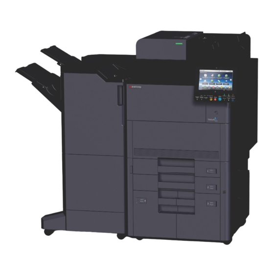
- Page 42 2WA/2NJ/2RK (1-3) With Optional Equipments Attached 1. Tray 1 to 7 (tray 1 is the top tray) 7. Cassette 6 2. Tray A 8. Cassette 7 3. Tray B 9. Control Section of the Finisher 4. Tray C 5. Folded in the middle 6.
- Page 43 2WA/2NJ/2RK (1-4) FAX System 1. LINE Connector (L2) If installing 2 FAX kits, 2 ports are available. Connect the modular cords for telephone line. 2. LINE Connector (L1) Connect the modular cords for telephone line. This connector is port 1. 3.
- Page 44 2WA/2NJ/2RK (1-5) Operation Panel Keys 1. [Home] key: Displays the Home screen. 2. [Numeric Keypad] key: Displays numeric keys on the touch panel. 3. Function Key: These keys enable various functions and applications, including copy and scan, to be regis- tered.
- Page 45 2WA/2NJ/2RK 1-3 Optional Equipment The following options are available for this machine. 1-19...
- Page 46 2WA/2NJ/2RK 1-20...
- Page 47 2WA/2NJ/2RK (1) Option (1-1) MT-730(B) "Mailbox" Makes it easy to sort output into separate trays. Installing this option adds 7 output trays. When multiple computer users share the printer, each user can print to a specified tray. Installs on the 4,000-Sheet Finisher. (1-2) DF-7110 "4,000-Sheet Finisher"...
- Page 48 2WA/2NJ/2RK (1-9) Copy tray(D) "copy tray" These are attached to the left side of the machine when the optional 4,000-Sheet Finisher is not used. There are two trays: the Upper Left Tray and the Lower Left Tray. (1-10) NK-7100, NK-7110 "Optional Numeric keyboard" The numeric keypad is added to the operation panel.
- Page 49 2WA/2NJ/2RK (1-19) Data Security Kit(E) "Data Security Kit" The Data Security Kit overwrites all unnecessary data in the storage area of the hard disk so that it cannot be retrieved. The Data Security Kit encrypts data before storing it in the hard disk. It guarantees higher security because no data can- not be decoded by ordinary output or operations.
- Page 50 2WA/2NJ/2RK-2 2 Installation 2-1 Environment Installation environment 1. Temperature: 50 to 90.5°F (10 to 32.5°C) (But humidity should be 70% or less when the temperature is 90.5°F (32.5°C).) 2. Humidity: 10 to 80%(But the temperature should be 86°F (30°C) or less when humidity is 80%.) 3.
- Page 51 2NJ/2RK-1 2-2 Installing the main unit Installation procedures START Unpacking and checking bundled items Connecting the Interface Cable Take out of the machine unit Connecting the FAX cable (FAX installation only) Take out of fixed tape and cushioning material Loading Paper Change to the operation unit position Connecting the Power Cord Toner collection box attaching...
- Page 52 2NJ/2RK-1 Image adjustment Execute the Maintenance mode U952 *: When setting up at high altitude Maintenance mode workflow (:Execute/ HIGH ALTITUDE) Developer bias adjustment (Maintenance mode U140) Maintenance mode workflow (:Execute/ SET UP) Setting the ID correction operation (Maintenance mode U464) Adjusting the halftone automatically (Maintenance mode U410) Output a Maintenance report...
- Page 53 2NJ/2RK (1) Unpacking and checking bundled items (1-1) Machine 27 28 16,17,18 19,20 Figure 2-2 1. Main unit 12. Machine cover 23. Toner collection box case 2. Upper case 13. Front pad 24. Air cap bag 3. Outer case 14. Operation cover 25.
- Page 54 2NJ/2RK (1-2) Take out of the machine unit Take out the main unit and accessories from the packing case. *: When taking out of the machine unit, it needs about 2m spaces behind the machine. 1. Detach the hinge joint, remove outer case, inner case, left upper/right pad, left/right stay, front pad, upper spacer and bottom spacer.
- Page 55 2NJ/2RK-1 5. Check that there is no step on a circle frame of slope(a). 6. Open the product cover(b). 7. Lift each left and right machine unit, remove the left bottom pad(c), the right bottom pad(d) and the product cover(b). Figure 2-5 8.
- Page 56 2NJ/2RK (1-3) Take out of fixed tape and cushioning material Remove the tape and cushioning materials for packing from the main unit. (2) Notes on main unit transportation *: When carrying the main unit, taking out of the machine right lower side of conveying handle(a) and with four people as shown in the figure and hold the conveying handle and three handles(b).
- Page 57 2NJ/2RK (3) Change to the operation unit position *: The operation unit position can be set to right side or left side of the machine. When shipping, it is set at the left side. When setting the operation unit position to the right side of the machine. 1.
- Page 58 2NJ/2RK 4. Secure the operation unit (b) by two removed pins (a). Figure 2-10 5. Reinstall the rear operation unit cover (a) removed in step 2. Figure 2-11...
- Page 59 2NJ/2RK (4) Toner collection box attaching 1. Detach the tape(b) from the toner collection box(a). 2. Detach the cable cover(c). Figure 2-12 3. Install the toner collection box(a) with three bundled screws(b)(M3×8 S-tite). Figure 2-13 2-10...
- Page 60 2NJ/2RK 4. Install the connector(a). 5. Install the cable cover(c) with one screw(b)(M3×8 P-tite). *: When switching on without installing the toner col- lection box(d), it causes the below C call, FAN1 disconnection : C7470 FAN2 disconnection : C7480 Figure 2-14 2-11...
- Page 61 2NJ/2RK (5) Release the lock of the scanner mirror frame 1. Open the document processor(a). 2. Detach the tape(e) and then detach the ISU lock leaflet(f). 3. Raise the triangle mark side of the optical lock cover (c) with a flat-blade screwdriver (b) and slide it in the direction of the arrow to remove it.
- Page 62 2NJ/2RK (6) Release of lift plate stopper 1. Pull cassette 1 and 2(a), remove each lift plate stopper(b) and attach them to the storage location. *: When moving the machine, attach the lift plate in original position. Cassette 1,2 Figure 2-16 Cassette 3,4 1.
- Page 63 2NJ/2RK (7) Release the lock of developer waste outlet Caution To ease setup, the device was shipped with the developer unit already replenished with developer. Therefore, to prevent developer from spilling during shipping, a developer shutter is equipped with the developer unit.
- Page 64 2NJ/2RK 5. Remove one screw (a)(M4x8) and then open the front middle cover(b). Figure 2-20 6. Press the fixing pin(a) and rotate. *: Fully insert the fixing pin(a) with keeping the protru- sions(b) vertical and rotate it by 90 degrees clock- wise.
- Page 65 2NJ/2RK 7. Remove a screw(a) and slide the lever right wards. 8. Fix the lever(b) using the screw(a) previously removed at the right screw hole and unlock the developer waste exit. *: When the device is shipped again or removed, use the reverse procedure to lock in the developer waste exit.
- Page 66 2NJ/2RK (9) Installation of the metal fittings to prevent falling down When the optional document finisher or the side paper feeder is installed, the stabilizers are not required. 1. Fix the stabilizers(b) with two screws(a)(M4×20) as shown. *: The upper side of screw hole is used. Figure 2-24 Note *: Turn til1 the position which the adjuster(a) contacts...
- Page 67 2NJ/2RK (10)Connecting the Interface Cable Connection Environ- Function Necessary Cable ment Connect a LAN cable to Printer/Scanner/Network LAN Cable the main unit (10Base-T, 100Base-TX or 1000Base-T) Connect a USB cable Printer USB2.0 compatible cable (Hi-Speed USB compliant, Max. to the main unit 5.0m long) When Connecting the Machine to the PC on the Network Network...
- Page 68 2NJ/2RK 2. Connect the LAN cable to the network interface connector. Figure 2-28 3. Pass the cord through the groove. Figure 2-29 4. While taking care not to insert the cord and then install in order from the lower. Figure 2-30 5.
- Page 69 2NJ/2RK When Connecting the Machine to the PC via USB Figure 2-31 1. Connect the USB cable to the USB interface connector located on the rear side of the main unit. Figure 2-32 2. Connect the other end of the cable to the PC. 2-20...
- Page 70 2NJ/2RK (11)Connecting the FAX cable (FAX installation only) General FAX connection example In the case of the general telephone line a. Modular jack Figure 2-33 ADSL Connect a cord between the LINE connector of the main unit and the PHONE port of the splitter. a.
- Page 71 2NJ/2RK Modular cord connection Connect a modular cord to the LINE connector of the main unit. When using a commercially available telephone set, connect a modular cord to the TEL connector of the main unit. 1. Detach the main unit cover in order from the top. Figure 2-36 2.
- Page 72 2NJ/2RK 3. Pass the cord through the groove. Figure 2-38 4. While taking care not to insert the cord and then install in order from the lower. Figure 2-39 2-23...
- Page 73 2NJ/2RK (12)Loading Paper (12-1) Precaution for Loading Paper Before loading paper in the cassette, fan the paper taken from a new package to separate it in the procedures below. Figure 2-40 Fan the paper and align the edges at the flat place. In addition, note the following points.
- Page 74 2NJ/2RK (12-2) Set paper in the cassette Set the paper to the cassette 1, cassette 2, optional cassette 5(PF-7130), cassette 6(PF-730) and cassette 7(PF- 730). The following procedure is an example for the cassette 1. 1. Pull the cassette completely out of the main unit. Figure 2-41 Note Do not pull out multiple cassettes simultaneously.
- Page 75 2NJ/2RK 3. Release the lock of the paper width guides. Figure 2-44 4. Adjust the position of the paper width guides. Figure 2-45 5. Load paper. Figure 2-46 Note Load the paper with the print side facing up. Before loading paper in the cassette, fan the paper taken from a new package to separate it. (P.2-24See page ) Before loading the paper, be sure that it is not curled or folded.
- Page 76 2NJ/2RK 6. Check the paper length guide and paper width guide are securely aligned to the paper. *: Re-align the paper length guide or paper width guide if gaps are observed. Figure 2-47 7. Lock the paper width guide Figure 2-48 8.
- Page 77 2NJ/2RK 10. Insert the paper size and media type sheet(cassette 1 and cassette 2 only). Figure 2-51 2-28...
- Page 78 2NJ/2RK-1 (12-3) Set paper in the large capacity feeder *: Set the paper to the cassette 3, cassette 4, optional cassette 6(PF-740) and cassette 7(PF-740). The following pro- cedure is an example for the 3rd cassette. *: The following procedures are for Metric mode. The parts below are necessary to change paper size from Letter to A4/B5 in Inch mode.
- Page 79 2NJ/2RK 2.Match to usable paper size and then insert the groove (the bottom of the tray) which fix the paper size guide A(a). Figure 2-54 Check if the top of paper size guide A(a) matches the usable paper size, install the fixed material(b) and lock turning. Move slightly, check that the paper size guide is fixed.
- Page 80 2NJ/2RK-1 In the case of A4 Insert the paper size B(c) into the A4 marking groove (the bottom of the tray) and then fix the hook. (When the hook is fixed, it snaps.) Move slightly, check that the paper size guide is fixed. Figure 2-56 Inch model (Letter →...
- Page 81 2NJ/2RK In the case of B5 Open the paper size guide B(c) as shown the diagram, insert the B5 marking groove(the bottom of the tray) and then fix the hook. (When the hook is fixed, it snaps.) Move slightly, check that the paper size guide is fixed. Figure 2-58 In the case of letter The paper size guide B(c) is not installed.
- Page 82 2NJ/2RK 5.Load paper. Figure 2-60 Note Load the paper with the print side facing up. Before loading paper in the cassette, fan the paper taken from a new package to separate it. (P.2-24See page ) Before loading the paper, be sure that it is not curled or folded. Such paper may cause paper jams. Make sure that the loaded paper does not exceed the level indicator (see the illustration above).
- Page 83 2NJ/2RK 8.Insert the paper size and media type sheet(cassette 3 and cassette 4 only). Figure 2-63 2-34...
- Page 84 2NJ/2RK (12-4) Set paper in the side feeder 1. Pull the cassette completely out of the main unit. Figure 2-64 2. Load paper. *: Initial paper size is A4. When the paper size is wanted to change B5 or Letter, refer to the installation guide. Figure 2-65 Note Load the paper with the print side facing up.
- Page 85 2NJ/2RK 3. Gently insert the cassette all the way. Figure 2-66 4. Insert the paper size sheet and media type sheet. Figure 2-67 2-36...
- Page 86 2WA/2NJ/2RK-2 (13)Connecting the Power Cord 1. Connect one end of the supplied power cord (a) to the machine and the other to a power outlet. *: Connect the power plug to the another circuit outlet. (100V: 80 ppm model) *: Only use the power cord that comes with the main unit. *: A power cord is attached to the 120V machine.
- Page 87 2NJ/2RK (14)Input of the power source Open the main switch lid (a) and turn the main switch (b) on. Figure 2-71 2-38...
- Page 88 2NJ/2RK (15)Setting up the Toner Container Set up the toner container. 1. Lift the angle of operation panel up to the most top and then open the front cover. Figure 2-72 2. Take out the toner container. Figure 2-73 IMPORTANT Do not touch the toner outlet by hand.
- Page 89 2NJ/2RK 3. Slightly tap the toner container. Figure 2-75 4. Shake the toner container. Figure 2-76 5. Install the toner container. Figure 2-77 6. Lock the toner container lever. Figure 2-78 2-40...
- Page 90 2NJ/2RK 7. Close the front cover. Figure 2-79 2-41...
- Page 91 2NJ/2RK (16)Default Setting The Machine Setup Wizard is launched when the equipment is turned on for the first time after being installed. Avail- able of setting the necessary items. Also, it can beset from System Menu as below. [System Menu/ Counter] key Figure 2-80 (16-1)Setting Date and Time Follow the steps below to set the local date and time at the place of installation.
- Page 92 2WA/2NJ/2RK-2 (16-2) Network Setup (LAN Cable Connection) TCP/IP (IPv4) Settings Set up TCP/IP (IPv4) to connect to the Windows network. The default settings are as follows. • TCP/IP: On • DHCP: On • Auto-IP: On • IP Address: 0.0.0.0 • Subnet Mask: 0.0.0.0 •...
- Page 93 2NJ/2RK-1 (18)Image adjusting Execute the image adjusting in the maintenance mode workflow (Maintenance mode U952 ) 1. Input "10871087" using the numeric keypad to enter the maintenance mode. 2. Input "952" using the numeric keypad and press the [Start] key. 3.
- Page 94 2NJ/2RK (18-3) Adjusting the halftone automatically (Maintenance mode U410) 1.Input "410" using the numeric keys. 2.Press the [Start] key. * :Execution information screen is displayed. * :Test pattern 1 and Test pattern 2 are output on A4/ letter paper. 3.Set the Test Pattern 1 output as the original. Place the edge with the arrows toward the back and the printed side facing down on the platen.
- Page 95 2NJ/2RK (19)Cassette heater control setting (100V model only) *: The model which the cassette heater is normally equipped and connecting to the connector in the cassette heater connecting procedure. *: If the setting is not executed, the cassette heater is not turned on. (Default setting is OFF) 1.
- Page 96 2NJ/2RK 2-3 Installing the optional equipment (1) Gigabit Ethernet extension kit (IB-50) The bundle parts of Gigabit Ethernet extension kit (IB-50)(1505JV0UN0) PWB unit 1 pc Procedures 1. Press the power key, after checking that the power lamp and the memory lamp are turned off, switch the main power off and unplug the power plug.
- Page 97 2NJ/2RK 4. Remove two screws(a)(M3×8) and then remove the OPT2 slot cover (b). OPT2 Figure 2-86 5. Insert the Gigabit Ethernet extension kit (b) along the OPT2 groove(a), fix with two screws(c)(M3×8) which is removed in the procedure 4. *: Don't touch directly the terminal of Gigabit Ethernet extension kit.
- Page 98 2NJ/2RK 6. Insert the LAN cable(a) into the connector. Figure 2-88 7. Pass the cord through the groove. Figure 2-89 8. While taking care not to insert the cord and then install in order from the lower. Figure 2-90 *: Insert the bundled CD-ROM into PC, executing "Quick Network Setup" and set the IP address. 2-49...
- Page 99 2NJ/2RK (2) Wireless LAN interface kit(IB-51) Bundled parts of Wireless LAN interface kit(IB-51)(1505J50UN0) PWB unit 1 pc Procedures 1. Press the power key, after checking that the power lamp and the memory lamp are turned off, switch the main power off and unplug the power plug.
- Page 100 2NJ/2RK 4. Insert the Wireless interface kit (b) along the OPT2 groove(a), fix with two screws(c)(M3×8) which is removed in the procedure 3. *: Don't touch directly the terminal of Wireless inter- face kit. When inserting Wireless interface kit, you have to hold PWB upper and lower parts or protuberance.
- Page 101 2NJ/2RK (3) Wireless LAN interface (IB-35) (120V model standard) Bundled parts of Wireless LAN interface (IB-35)(1503RR0UN0) PWB unit 1 pc Screw (M3x6) 1 pc Procedures 1. Turn off the main unit and disconnect the power cord and all interface cables. 2.
- Page 102 2NJ/2RK 4. Remove one screw (a)(M3x8). 5. Remove the IF lid(b) in the direction of the arrow. Figure 2-96 6. Insert the FPC (b) of the PWB unit (a) into the aperture (c) of the controller box. 7. Connect the connector (d) to the connector (f) of the main PWB (e). Figure 2-97 2-53...
- Page 103 2NJ/2RK 8. Secure the PWB unit (b) with a screw (a)(M3x6). Figure 2-98 9. Reattach IF lid(b) in the original position with one screw(a)(M3×8). Figure 2-99 2-54...
- Page 104 2NJ/2RK 10. Hang the below side of three hooks(a) and then hang the top side of hooks(b) by sliding in the direction of the arrow. 11. Reattach the left rear cover(d) in the original position with one screw(c)(M3×8). Figure 2-100 2-55...
- Page 105 2NJ/2RK (4) Document table (DT-730(B)) Bundled parts of Document table DT-730(B) (1902LC0UN2) Tray stay 1 pc Tray mounting plate 1 pc Tray cover 1 pc Tray lower cover 1 pc Tray fixing plate 1 pc Sheet 2 pcs 2 pcs Nut M4 2 pcs Screw (M4x8 screw with the binding head)
- Page 106 2NJ/2RK 5. Remove two screws (a) (M4x8) and then detach the ISU right cover (b) in the direction of the arrow. Figure 2-103 6. Open the right tray (a). 7. Detach the right upper cover (b). Figure 2-104 2-57...
- Page 107 2NJ/2RK 8. Cut the separator cover (b) of the right upper cover (a) with nippers(c) etc. 9. Insert one nut(d) in the back side of the right upper cover (a). 10. Hang the hook(f) of the tray stay(e) on the aperture. 11.
- Page 108 2NJ/2RK 13. Reattach the ISU right cover (b) to the direction of the arrow in the original position with two screws (a)(M4×8). Figure 2-107 14. Reattach the rear operation cover (a) to the direction of the arrow in the original position with one screw (b)(M3×8). Figure 2-108 2-59...
- Page 109 2NJ/2RK 15. Insert the mounting plate (a) into the tray stay (B) and secure it with two screws (C) (M4×8). Figure 2-109 16. Attach the tray cover (b) to the tray stay (c) with four screws (a)(M4×8). Figure 2-110 2-60...
- Page 110 2NJ/2RK 17. Attach the tray lower cover (a). 18. Secure the tray lower cover (a) by two pins (b). Figure 2-111 19. Affix the two sheet (b) on the document table (a). Figure 2-112 2-61...
- Page 111 2NJ/2RK (5) Numeric keypad (NK-7100 / NK-7110) Numeric keypad installation requires the following parts. Numeric keypad 1 pc NK-7100(1903RT0UN0):100V/220 to 240V model NK-7110(1903RT0US0):120V model Bundled parts of numeric keypad NK-7100/NK-7110 Numeric Keypad 1 pc Numeric Keypad cover 1 pc Screw (M3x8) 2 pcs Label* 1 pc *:NK-7100 only...
- Page 112 2NJ/2RK 5. Latch two hooks (b) on the cut-out (c) of the operation unit, and then attach the numeric keypad (a) with two screws (d) (M3x8). Figure 2-116 6. Slid the cover (a) in the direction of the arrow and latch two hooks (b), and secure the screw (c)(M3x8) once removed in step 2.
- Page 113 2NJ/2RK (6) IC card reader IC card reader installation requires the following parts. IC card reader 1 pc Procedures 1. Turn the power switch off and disconnect the power plug. 2. Pull up the operation unit (a). 3. When the operation unit attaches to the left side, put the right aside.
- Page 114 2NJ/2RK 7. Remove two pins (a) (M4x6) and then remove the glass front cover (b) by sliding in the direction of the arrow. Figure 2-121 8. Remove the ISU front cover (b) in the direction of the arrow. Figure 2-122 9.
- Page 115 2NJ/2RK 10. Remove one screw (a) (M4x8), slide the fixed glass plate (c) in the direction of the arrow, remove the hook and then detach it. Figure 2-124 11. Remove the table glass (a) and sheet (b). Figure 2-125 12. Insert IC card reader (a) into the main unit holder (b). *: Differ the size by IC card reader.
- Page 116 2NJ/2RK Note in the installation When the outline of IC card reader is smaller than the holder, the receiving parts are positioned in a sheet marking position. (When it needs to fix, fix with the dual tape etc.) When the thickness of IC card reader is thin and there is far from the table glass, insert the spacer between the holder and then adjust the height (The space is to 5mm extent.) 13.
- Page 117 2NJ/2RK 16. Reattach the table glass (a) and sheet (b) in the original position. Figure 2-129 17. Hang three hooks (b) by sliding the fixed glass plate (c) in the direction of the arrow, reattach one screw (a) (M4×8) in the original position. *: Insert the right side under the wire guide(d) in advance.
- Page 118 2NJ/2RK 18. Hang three hooks (b) by sliding the operation rear cover B (a) in the direction of the arrow, reattach one screw (c) (M3×8) in the original position. Figure 2-131 19. Reattach the ISU front cover (b) in the direction of the arrow. Figure 2-132 20.
- Page 119 2NJ/2RK 21. Reattach the ISU right cover (b) to the direction of the arrow in the original position with two screws (a)(M4×8). 22. Close the document processor. Figure 2-134 23. Reattach the rear operation cover (a) to the direction of the arrow in the original position with one screw (b)(M3×8). *: When the operation unit is set at the left side, it is moved at the right side.
- Page 120 2NJ/2RK (7) USB keyboard (120V /220 to 240V model only) USB keyboard installation requires the following parts: Keyboard holder 10 (1709AN0UN0)1 pc USB Keyboard1 pc Bundled parts of Keyboard holder 10 (1709AN0UN0) Upper keyboard mounting bracket 1 pc Lower keyboard mounting bracket 1 pc Upper keyboard cover 1 pc Lower keyboard cover 1 pc Upper lid*...
- Page 121 2NJ/2RK 3. Insert two positioning pins (b) of lower keyboard cover (a) into the holes (d) of the upper keyboard mounting plate (c) and slide it in the direction of the arrow. 4. Insert the lower keyboard cover (a) into three hooks (e) on the keyboard mounting plate (a) and two cutouts (f). Figure 2-137 5.
- Page 122 2NJ/2RK 7. Open the document processor. 8. Remove two screws (a) (M4x8) and then detach the ISU right cover (b) in the direction of the arrow. Figure 2-140 9. Remove two pins (a) (M4x6) and then detach the glass front cover (b) by sliding in the direction of the arrow. Figure 2-141 10.
- Page 123 2NJ/2RK 11. Reattach the lower keyboard mounting plate (b) with two screws (a)(M3x8). Figure 2-143 12. Affix a pair of hook-and-loop fasteners (c) to the concave (b) of the upper keyboard cover (a). Figure 2-144 2-74...
- Page 124 2NJ/2RK 13. Place the keyboard (a) on the hook-and-loop fastener(b) and press it to fix. 14. Connect the USB cable (c) with the USB connector (d) on the main unit. Figure 2-145 15. Insert the USB cable (a) into the cable guide (b). Figure 2-146 2-75...
- Page 125 2NJ/2RK 16. Release two hooks (b) of the lid (c) from the ISU front cover (a) and then detach them Figure 2-147 17. Reattach the ISU front cover (a) in the original position. *: USB keyboard cable (c) passes through the space between ISU front cover (a) and the lower keyboard mounting plate (b).
- Page 126 2NJ/2RK *: Use the bundled cable ties (c) if necessary when tying cables. Figure 2-149 19. Slide the glass front cover (b) in the direction of the arrow and then reattach two pins (a)(M4×6) in the original posi- tion. Figure 2-150 2-77...
- Page 127 2NJ/2RK 20. Reattach the ISU right cover (b) to the direction of the arrow in the original position with two screws (a)(M4×8). 21. Close the document processor. Figure 2-151 2-78...
- Page 128 2NJ/2RK (8) Handset (100V model only) (8-1) When attaching the main unit directly Handset installation requires the following parts: Handset (1909AG9JP0)1 pc Bundled parts of handset (1909AC9JP0) Handset 1 pc Handset holder 1 pc Handset mounting plate 1pc Protection cover 1 pc Pin 2 pcs Telephone wire 1 pc Modular cord 1 pc...
- Page 129 2NJ/2RK 5. Remove two screws (a) (M4x8) and then detach the ISU right cover (b) in the direction of the arrow. Figure 2-154 6. Open the right tray (a). 7. Detach the right upper cover (b). Figure 2-155 2-80...
- Page 130 2NJ/2RK 8. Insert two nuts (b) in the back side of the right upper cover (a). 9. Attach the handset mounting plate (d) to the right upper cover (a) with two screws (c). *: The lower side of screw hole is used. *: While pressing the nuts(e), fasten the screw (c) not to fall them.
- Page 131 2NJ/2RK 10. Reattach the right upper cover (a) to the main unit in the original position, fasten with one screw(b)(M4×8). Figure 2-157 11. Reattach the ISU right cover (b) to the direction of the arrow in the original position with two screws (a)(M4×8). Figure 2-158 12.
- Page 132 2NJ/2RK 13. Remove two nuts (b) and two screws (c) from the handset mounting plate (a), attach the marking B position. Figure 2-160 2-83...
- Page 133 2NJ/2RK 14. Put the screws (c) at the backside built-in part (b) of the handset holder (b) and slide it toward you to secure it. Figure 2-161 2-84...
- Page 134 2NJ/2RK 15. Attach the protection cover (a) to the handset mounting plate (b). Figure 2-162 16. Connect the telephone wire (a) to the handset (b) and handset holder (c). Figure 2-163 2-85...
- Page 135 2NJ/2RK 17. Connect the modular cord (a) to the handset holder (b). Figure 2-164 18. Detach the controller cover(a). Figure 2-165 2-86...
- Page 136 2NJ/2RK 19. Detach the main unit cover(a) in order from the top. Figure 2-166 20. Connect one end of the connector (b) of the modular cord (a) to the machine left side. Figure 2-167 21. Pass the cord through the groove. Figure 2-168 2-87...
- Page 137 2NJ/2RK 22. While taking care not to insert the cord and then install in order from the lower. Figure 2-169 2-88...
- Page 138 2NJ/2RK (8-2) In case installing the document table Handset installation requires the following parts: Handset (1909AG9JP0) 1 pc Document table DT-5100 (1902LC0UN2) 1 pc Bundled parts of handset (1909AC9JP0) Handset 1 pc Handset holder 1 pc Handset mounting plate*1 1 pc Protection cover*1 1 pc Pin 2 pcs Telephone wire 1 pc...
- Page 139 2NJ/2RK 4. Remove one screw (a)(M4x8). Figure 2-171 5. Remove two screws (a)(M4x8) and then detach the ISU right cover (b) in the direction of the arrow. Figure 2-172 6. Open the right tray (a). 7. Detach the right upper cover (b). Figure 2-173 2-90...
- Page 140 2NJ/2RK 8. Take out cutting the separator cover (b) of the right upper cover (a) with nippers, etc. 9. Insert one nut(d) in the back side of the right upper cover (a). 10. Hang the hook(f) of the tray stay(e) on the aperture. 11.
- Page 141 2NJ/2RK 13. Reattach the ISU right cover (b) to the direction of the arrow in the original position with two screws (a)(M4×8). Figure 2-176 14. Reattach the rear operation cover (a) to the direction of the arrow in the original position with one screw (b)(M3×8). Figure 2-177 2-92...
- Page 142 2NJ/2RK 15. Insert the mounting plate (a) into the tray stay (B) and secure it with two screws (C) (M4×8). Figure 2-178 16. Attach the tray cover (b) to the tray stay (c) with four screws (a)(M4×8). Figure 2-179 2-93...
- Page 143 2NJ/2RK 17. Remove two pins (b) and two nuts (c) from the handset mounting plate (a). 18. Secure the original tray (d) with two pins and two nuts once removed. Figure 2-180 19. Put two catches (c) at the backside of the handset holder (b) into two pins (a) and slide it toward you to fix it on the document tray (d).
- Page 144 2NJ/2RK 20. Cut the separator cover (b) of the tray lower cover (a) with nippers, etc. Figure 2-182 21. Attach the tray lower cover (a). 22. Secure the tray lower cover (a) by two pins (b). Figure 2-183 23. Affix the sheet (b) on the left side of document table (a). Figure 2-184 2-95...
- Page 145 2NJ/2RK 24. Connect the telephone wire (a) to the handset (b) and handset holder (c). Figure 2-185 25. Connect the modular cord (a) to the handset holder (b). Figure 2-186 26. Detach the controller cover(a). Figure 2-187 2-96...
- Page 146 2NJ/2RK 27. Detach the main unit cover(a) in order from the top. Figure 2-188 28. Connect one end of the connector (b) of the modular cord (a) to the machine left side. Figure 2-189 29. Pass the cord through the groove. Figure 2-190 2-97...
- Page 147 2NJ/2RK 30. While taking care not to insert the cord and then install in order from the lower. Figure 2-191 2-98...
- Page 148 2NJ/2RK-1 (9) Cassette heater (9-1) In the case of main unit cassette (120V/220 to 240V models only) Cassette heater installed model as standard The cassette heater is not connected at factory but connect it according to the procedures below. Figure 2-192 Cassette heater connection (100V model only) 1.
- Page 149 2NJ/2RK-1 3. Remove four screws (a)(M3x8) and the detach right rear cover (b) in the direction of the arrow. Figure 2-195 4. Remove eight screws (a)(M3x8). 5. Remove two low side of hooks(b) and then the lower rear cover(c). Figure 2-196 2-100...
- Page 150 2NJ/2RK-1 6. Remove the cassette heater wire(b) combining from the wire saddle(a) and then fix it again. Figure 2-197 7. Connect the cassette heater connector(a) to the power source PWB(B)(YC4). Figure 2-198 8. Reattach the lower rear cover in the original position. 9.
- Page 151 2NJ/2RK Cassette heater non-installed model Cassette heater installation requires the following parts: 120V Cassette heater set (302NJ9416_) 1pc Bundle parts of cassette heater set(302NJ9416_) Cassette heater 120(302RH4404_) 2 pcs Connector cover 2pcs High temperature caution label 2 pcs Screws (M3x6 S-tite) 4 pcs Screws (M4x8 with the binding head) 2 pcs Wire saddles 8 pcs 220 to 240V...
- Page 152 2NJ/2RK 3. Remove two screws (a)(M3×8), release two hooks (b) and detach the stay (c). Figure 2-200 4. Pull out the upper cassette (a) from the main unit (b) and remove it in the direction of the arrow. Figure 2-201 2-103...
- Page 153 2NJ/2RK 5. Remove two screws (a)(M3×8), release two hooks (b) and detach the stay (c). Figure 2-202 2-104...
- Page 154 2NJ/2RK 6. 200 to 220V models only Remove one screw (a)(M4x8) and the detach the connector cover (b) in the direction of the arrow. Figure 2-203 7. Reattach four wire saddles (a) to the bottom frame (b). *: 220 to 240V model is 5pcs. 8.
- Page 155 2NJ/2RK 220_240V Figure 2-205 10. Insert two hooks (b) of the connector cover (a) into the hole (c). 11. Reattach the connector cover (a) with one screw (d) (M4x8). Figure 2-206 2-106...
- Page 156 2NJ/2RK 12. Clean the bottom frame (a) A parts with an alcohol, attach the caution label to it. Figure 2-207 13. Reattach the parts in the original position. 2-107...
- Page 157 2NJ/2RK Installing of cassette 3,4 1. Turn the power switch off and disconnect the power plug. 2. Pull out the right paper deck (a). 3. Remove the four screws(b)(M4×8) and detach the right paper deck (a). Figure 2-208 4. Pull out the left paper deck (a). 5.
- Page 158 2NJ/2RK 6. Reattach four wire saddles (a) to the main uint bottom frame (b). 7. Reattach the cassette heater(d) with two screws(c)(M3×8). Figure 2-210 8. Pass through the cassette heater wire (a) in four wire saddles (b). 9. Connect the connector (c) of the cassette heater to the connector (d) of the main unit rear frame. Figure 2-211 2-109...
- Page 159 2NJ/2RK 10. Insert two hooks (b) of the connector cover (a) into the hole (c). 11. Reattach the connector cover (a) with one screw (d) (M4x8). Figure 2-212 12. Clean the bottom frame (a) in front of the cassette heater with an alcohol. 13.
- Page 160 2NJ/2RK (9-2) In case of Paper Feeder (PF-730(B)) Cassette heater installation requires the following parts: Cassette heater 100 set (303NJ9406_) 1 pc Cassette heater 120 set (303NJ9407_) Cassette heater 240 set (303NJ9408_) Bundled parts of cassette heater 100/120/240 set Cassette heater 100 (302H74507_) 1 pc Cassette heater 120 (302H74509_) Cassette heater 240 (302H74508_)
- Page 161 2NJ/2RK 4. Reattach three wire saddles (a) to the paper feeder bottom frame (b). 5. Reattach the cassette heater(d) with two screws(c)(M4×8). Figure 2-216 2-112...
- Page 162 2NJ/2RK 6. Connect the connector (b) of the cassette heater (a) to the connector (c) of the paper feeder rear frame. 7. Pass through the cassette heater wire (d) in three wire saddles (e). Figure 2-217 8. Insert two hooks (b) of the heater cover (a) into the hole. 9.
- Page 163 2NJ/2RK 10. Clean the bottom frame in front of the cassette heater with an alcohol. 11. Match the corner of the bottom frame marking (a) and attach the high temperature caution label (b). Figure 2-219 12. Reattach the parts in the original position. 13.
- Page 164 2NJ/2RK (9-3) In case of Paper Feeder (PF-740(B)) Cassette heater installation requires the following parts: Cassette heater 100 set (303NF9412_) 1 pc Cassette heater 120 set (303NF9413_) Cassette heater 240 set (302NF9414_) Bundled parts of cassette heater 100/120/240 set Cassette heater 100 (302H74507_) 1 pc Cassette heater 120 (302H74509_) Cassette heater 240 (302H74508_) High temperature caution label 1 pc...
- Page 165 2NJ/2RK 1. Pull out the left cassette (a). 2. Remove four screws(b)(M4×8) and detach the left cassette (a). Figure 2-221 2-116...
- Page 166 2NJ/2RK 3. Reattach three wire saddles (a) to the paper feeder bottom frame (b). 4. Reattach the cassette heater(d) with two screws(c)(M3×8). Figure 2-222 2-117...
- Page 167 2NJ/2RK 5. Connect the connector (b) of the cassette heater (a) to the connector (c) of the paper feeder rear frame. 6. Pass through the cassette heater wire (d) in three wire saddles (e). Figure 2-223 7. Insert two hooks (b) of the heater cover (a) into the hole. 8.
- Page 168 2NJ/2RK 9. Clean the bottom frame in front of the cassette heater with an alcohol. 10. Match the corner of the bottom frame marking (a) and attach the high temperature caution label (b). Figure 2-225 11. Reattach the parts in the original position. 12.
- Page 169 2NJ/2RK (9-4) In case of Side Paper Feeder (PF-7120) Cassette heater installation requires the following parts: Cassette heater 100 set (303RL9404_) 1 pc Cassette heater 120 set (303RL9405_) Cassette heater 240 set (303RL9406_) Bundled parts of cassette heater 100/120/240 set Cassette heater 100 assembly 1 pc Cassette heater 120 assembly Cassette heater 240 assembly...
- Page 170 2NJ/2RK 5. Release four bosses (a) and remove the right cover (b) while sliding it in the direction of the arrow. Figure 2-228 6. Pass the heater cassette cable (a) through the aperture. 7. Insert the hook (d) of the cassette heater set (c) into two lancings (e) and secure it with two screws (M3×8) (f). Figure 2-229 2-121...
- Page 171 2NJ/2RK 8. Connect the connector (b) of cassette heater wire (a) to the connector (c) of the inlet cable. 9. Attach two wire saddles (d) and the edge saddles (e) and secure the wire. 10. Attach the right cover and the rear cover. Figure 2-230 (Main unit side) 11.
- Page 172 2NJ/2RK 12. Connect the connector (b) of the heater outlet set (a) to the paper feeder side connector (c). 13. Attach the heater outlet set (a) with two screws (d)(M3×8). Figure 2-232 14. Connect the side feeder (a) to the main unit side paper feeder (b) with the AC cord (c) and the connector wire (d). Figure 2-233 15.
- Page 173 2NJ/2RK (10)In the case of side multi tray(PF-7130) Cassette heater installation requires the following parts: Cassette heater 100 set (303NG9407_) 1 pc Cassette heater 120 set (303NG9408_) Cassette heater 240 set (303NG9409_) Bundled parts of cassette heater 100/120/240 set Cassette heater 100 1 pc Cassette heater 120 assembly Cassette heater 240 assembly Heater outlet assembly 1pc...
- Page 174 2NJ/2RK 2. Insert the flathead screwdriver (c) into two inlays (b)(Left/Right) of the frame film A (a), and then detach to lift the claw to the top. 3. Remove four screws and then remove the rear cover. Figure 2-235 4. Reverse upper and lower parts of side multi tray (a).
- Page 175 2NJ/2RK 6. Inside out the bottom frame (a) and reattach three wire saddles (b). 7. Reattach the cassette heater(d) with two screws(c)(M3×8). Figure 2-237 8. Pass through the cassette heater wire (a) in three wire saddles (b). Figure 2-238 2-126...
- Page 176 2NJ/2RK 9. Inside out the bottom frame (a), reattach the edg- ing saddle (c) to the rear frame (b) and then pass through the cassette heater wire (d). 10. Reattach the bottom frame (a) in the original posi- tion. *: Do not insert the frame film A (e). Pass through the lower side of the stay frame (f).
- Page 177 2NJ/2RK 13. Insert the connector (a) of the cassette heater into the main unit PF side of connector (b). 14. Reattach the rear cover and the cassette in the original position. Figure 2-241 (Main unit paper feeder side) 15. Remove two screws (a)(M4×8) and remove the cover plate (b) from the main unit side paper feeder.
- Page 178 2NJ/2RK 16. Connect the connector (b) of the heater outlet assembly (a) to the paper feeder side connector (c). 17. Reattach with two screws (d)(M4×8) which is detached the heater outlet assembly (a). Figure 2-243 2-129...
- Page 179 2NJ/2RK 18. Connect to the side multi tray (a) and the main unit side paper feeder (b) with the AC cord (c) and the connector wire (d). 19. Turn the power on and set to [mode1/mode2] In maintenance mode U327 [Cassette heater control setting].
- Page 180 2NJ/2RK (11)Coin Vendor (100V model only) Coin vendor installation requires the following parts: Coin Vendor (1905H99JP0) 1 pc Vendor relay wire (302RH4622_)1 pc Bundled parts of Coin Vendor (1905H99JP0) Vendor wire 1 pc Vender base 1 pc Screws (M4x6) 4 pcs Procedures 1.
- Page 181 2NJ/2RK 4. Remove one screw (a)(M3x8) And then remove the left rear cover (b) by sliding in the direction of the arrow. Figure 2-247 5. Remove four screws (a)(M3x8) and the detach right rear cover (b) in the direction of the arrow. Figure 2-248 2-132...
- Page 182 2NJ/2RK 6. Due to the prevention of floor dirty and damage by toner falling, the sheet (b) is laid under the toner collection box (a). 7. Remove one screw (c)(M3×8) and detach the cable cover (d). 8. Detach one connector (e). Figure 2-249 2-133...
- Page 183 2NJ/2RK 9. Remove nine screws (a)(M3x8). 10. Detach the lower side of two hooks (c) and detach the lower rear cover (b) in the direction of the arrow. Figure 2-250 11. Remove one screw (a)(M3×8) and detach the DPIF lid (b). Figure 2-251 2-134...
- Page 184 2NJ/2RK 12. Detach one connector (a), release the wire saddle (b) and then remove the wire (c). Figure 2-252 13. Detach nine connectors from the main PWB (a). 14. Release eight wire saddles (b) and then remove the wire (e). 15.
- Page 185 2NJ/2RK-1 17. Remove three screws (a)(M4x8) and then detach the controller box (b). *: Release to lift the hook (c). *: When IB-35 is equipped, detach it. Figure 2-254 2-136...
- Page 186 2NJ/2RK 18. Remove two screws (a)(M3×8) and remove the concealing lid (b). Figure 2-255 19. Pass the vendor wire (a) through the aperture of IF mount (b). 20. Secure the vendor cable (a) with two screws (c) once removed in step 19. 21.
- Page 187 2NJ/2RK 22. Pull the earth wire (a) to the side of the wire saddle (b), bundle the extra, fix in the wire saddle (b) with the vendor wire (c). *: Line process so that the earth wire (a) does not touch the fan motor (d). Figure 2-257 23.
- Page 188 2NJ/2RK 24. Pass the vendor relay wire (a) in a wire guide (c) and ten wire saddles (d) and then fix it. Figure 2-259 25. Connect the connector (a) of the vendor relay wire to the vendor wire (b). Figure 2-260 2-139...
- Page 189 2NJ/2RK 26. Reattach the controller box in the original position. 27. Attach the lower rear cover, the right rear cover and the left rear cover in the original position. 28. Reattach the controller cover in the original position. 29. Connect the signal wire (b) of the coin vendor to the connector (a) of the vendor wire. Figure 2-261 30.
- Page 190 2NJ/2RK (12)Banner Tray Installation of banner tray requires the following parts: Banner Guide 10 (1203RP0UN0)1 pc Bundled parts of Banner Guide 10 (1203RP0UN0) Tray base 1 pc paper guide A 1 pc paper guide B 1 pc paper guide C 1 pc Procedures 1.
- Page 191 2NJ/2RK 4. Put the banner tray (a) on the MP tray (b) and attach sliding in the direction of the arrow till locking. Figure 2-265 2-142...
- Page 192 2WA/2NJ/2RK-2 2-4 About Optional Applications application Data Security Kit Internet FAX kit Card Authentication Kit*1 Emulation upgrade kit ThinPrint Option*1 *1: This can be used on a trial basis for a limited time. *: Restrictions such as the number of times the application can be used during the trial period differ depending on the application.
- Page 193 2WA/2NJ/2RK-2 2-5 Initializing procedures after installing the FAX system 1. Connect the power plug of the main unit to the outlet and turn the power on. 2. Input "10871087" using the numeric keys to enter the maintenance mode. 3. Input "600" using the numeric keys and press the [Start] key. 4.
- Page 194 2NJ/2RK IMPORTANT Note the following points when installing the FAX system in the line via ISDN or PBX. Check if the line to connect supports the V.34 (Super G3) FAX communication. Especially, when communicating between extensions in PBX (private line via TDM), only 14400bps or 9600bps of FAX communication speed is guaranteed and communication errors or TX/RX image failure may occur at V.34 com- munication in such a line.
- Page 195 2NJ/2RK 2-6 Installing the option unit (1) Unpacking and checking bundled items (1-1) Paper Feeder (PF-730(B)) 18 19 20 22 23 24 Figure 2-266 1. Main unit 7. Main unit cover 13. Front right upper pad 2. Outer case 8. Size label 14.
- Page 196 2NJ/2RK-1 (1-2) Paper Feeder (PF-740(B)) 18 19 20 22 23 24 Figure 2-267 1. Main unit 7. Main unit cover 13. Front right upper pad 2. Outer case 8. Size label 14. Rear right upper pad 3. Left bottom pad 9.
- Page 197 2NJ/2RK (1-3) Side Paper Feeder (PF-7120) Figure 2-268 1. Outer case 11. Upper pad 21. Cover plate 2. Inner frame 12. Size label 22. Attachment B 3. Bottom pad 13. Attachment A 23. Spanner 4. Bottom cushioning material 14. Guide film A 24.
- Page 198 2NJ/2RK (1-4) Side multi tray(PF-7130) 13 14 Figure 2-269 1. Outer case 13. Poly bag 25. Lock pin 2. Bottom cushion 14. Large base slider 26. Switch contacting board 3. Bottom spacer 15. Spacer A 27. Screw (M4x10) 4. Side multi tray 16.
- Page 199 2NJ/2RK-1 (1-5) 4,000-sheet Finisher (DF-7110) 17 18 19 Figure 2-270 1. Skid 9. Right spacer 17. Screw (M4x20) 2. Front bottom pad 10. Main tray 18. Connector cover 3. Rear bottom pad 11. Inner pad 19. Tray label 4. 4,000-sheets Finisher 12.
- Page 200 2NJ/2RK (1-6) Mailbox (MT-730(B)) Figure 2-271 1. Mailbox 7. Center bottom pad 13. Upper front Cover 2. Outer case 8. Side spacer 14. Upper rear cover 3. Inner frame 9. Accessory case 15. Screw (M4x12) 4. Bottom pad A 10. Tray 16.
- Page 201 2NJ/2RK (1-7) Center-Folding Unit (BF-730) 23 24 25 26 Figure 2-272 1. Outer case 11. Spacer E 21. Front side cover 2. Bottom spacer 12. Center-folding eject tray 22. Rear side cover 3. Spacer A 13. Spacer F 23. Pin 4.
- Page 202 2WA/2NJ/2RK-2 (1-8) Punch Unit (PH-7B) Figure 2-273 1. Outer case 4. Upper pad 7. Drive unit 2. Bottom pad 5. Punch PWB 8. Waste punch box 3. Punch unit 6. Waste punch box guide 2-153...
- Page 203 2NJ/2RK-1 (2) Optional unit installation Install necessary optional units in the main unit by Refer ring to the installation procedures. Product name Refer to the installation guide PF-7130(Multi media side tray) PF-7130+PF-730(B)/ PF- PF-730(B) (500x2 Paper Feeder) 740(B) PF-7130(Multi media side tray) PF-740(B) (500x2 Paper Feeder) PF-7120 (3000 Side Paper Feeder) PF-7120...
- Page 204 2NJ/2RK-1 (4) Attach the optional cable. The following parts are necessary in order to attach the optional cable. • Key counter wire (302MV4609_)1 pc Procedures 1. Turn the power switch off and disconnect the power plug. 2. Tilt up the operation unit (a). 3.
- Page 205 2NJ/2RK-1 5. Remove two screws (a)(M4x8) and then remove the ISU right cover (b). 6. Release six hooks (c) and remove the right upper cover (d). 14j0216 Figure 2-277 7. Take out cutting the separator cover (b) of the right upper cover (a) with nippers, etc.
- Page 206 2NJ/2RK-1 8. Remove the controller cover (a). 14j0200 Figure 2-279 9. Remove the screw (a)(M3x8TP) and remove the rear left cover (b) by sliding it in the direction of the arrow. 14j0201 Figure 2-280 2-157...
- Page 207 2NJ/2RK-1 *: When reattaching the rear left cover (b), latch three lower hooks (a) and then latch three upper hooks (b) while sliding in the direction of the arrow. 14j0202 Figure 2-281 10. Remove four screws (a)(M3x8) and remove the rear right cover (b) in the direction of the arrow.
- Page 208 2NJ/2RK-1 11. Remove the screw (a)(M3x8) and remove the DPIF lid (b). 14j0400 Figure 2-283 12. Disconnect the connector (a) and release the wire saddle (b) to remove the wire (c). 14j0401 Figure 2-284 2-159...
- Page 209 2NJ/2RK-1 When IB-35 is installed, remove it by the following procedure (steps 6 to 10). Other than that, go to step 11. 13. Remove the screw (a)(M3x8). 14. Detach the IF lid (b) in the direction of the arrow. 14j0403 Figure 2-285 15.
- Page 210 2NJ/2RK-1 16. Disconnect the connector (a) from the main PWB connector (c). 17. Remove the PWB unit (d). IMPORTANT When disconnect the connector (a) from the connector of main PWB (b), straightly pull out against the main PWB (b) and do not pull out on the skew. When pulling out on the skew, it causes the damage of FPC (f).
- Page 211 2NJ/2RK-1 18. Disconnect nine connectors from the main PWB (a). 19. Release seven wire saddles (b) and remove the wire. 20. Release the cable tie with a snap (c). 21. Remove the edge saddle (d) and remove the wire. YC62 YC42 YC32 YC23 YC33 YC51...
- Page 212 2NJ/2RK-1 22. Remove three screws (a)(M4x8) and remove the controller box (b). *:Release the hook (c) by lifting. 14j0407 Figure 2-289 2-163...
- Page 213 2NJ/2RK-1 23. Connect the connector of the key counter wire (a) to the connector (f) (YC38) of the engine PWB (e). YC38 12j070a Figure 2-290 24. Release six wire saddles (a). 25. Pass the key counter wire (b) through six of the wire saddle (a) and fix it.
- Page 214 2NJ/2RK 30. Pass the key counter wire connector (c) from the opening (b) of the right upper cover (a). 31. Reattach the right upper cover (a) in the original position. 32. Reattach the ISU right cover (d) in the original position.
- Page 215 2WA/2NJ/2RK 3 Machine Design Mechanical Configuration (1) Cross-section view Paper path Original path Optical path Figure 3-1 1. Paper feed section of Cas- 6. Laser scanner unit 12. Feedshift and eject section sette 1 and 2 7. Drum unit 13. Duplex conveying section 2.
- Page 216 2WA/2NJ/2RK (2) Document processor cross-section view Original path Figure 3-2 1. DP original feed section 3. DP original eject section 2. DP conveying section...
- Page 217 2WA/2NJ/2RK Extension device construction (option) (1) Paper feeder cross-section view (PF-730(B)) Paper path Figure 3-3 1. Cassette paper feed section (Cassette 6) 2. Cassette paper feed section (Cassette 7) (2) Paper feeder cross-section view (PF-740(B)) Paper path Figure 3-4 1. Right paper feed section (Cassette 6) 3.
- Page 218 2WA/2NJ/2RK (3) Paper feeder cross-section view (PF-7120) Paper path Figure 3-5 1. Paper deck feed section (Cassette 5)
- Page 219 2WA/2NJ/2RK (4) Paper feeder cross-section view (PF-7130) Paper path Figure 3-6 1. Cassette paper feed section (Cassette 5) 3. Exit section 2. Conveying section...
- Page 220 2WA/2NJ/2RK (5) 4000-sheet Finisher cross-section view (DF-7110) Paper path Figure 3-7 1. Punch unit 4. Eject section (tray B) 2. Conveying section 5. Eject section (tray A) 3. Staple unit 6. Eject section (tray C)
- Page 221 2WA/2NJ/2RK (6) Mailbox cross-section view (MT-730(B)) Paper path Figure 3-8 1. Conveying section 3. Eject section (tray B:DF) 2. Eject section (mail tray)
- Page 222 2WA/2NJ/2RK (7) Folding unit cross-section view (BF-730) Paper path Figure 3-9 1. Conveying section 3. Paper folding section 2. Staple unit 4. Exit section...
- Page 223 2WA/2NJ/2RK Paper conveying and Paper detection (1) Main unit+PF-730(B)+PF-7130+DF-7110+MT-730(B)+BF-730+PH-7 Mailbox 4000-Sheet Finisher (DF) Document Processor (DP) J 49xx J 40xx Side multi tray J 05x9 J 37xx J 36 xx Paper Feeder Figure 3-10 1. Paper feed sensor 1 16. PF conveying sensor 2 30.
- Page 224 2WA/2NJ/2RK Electric parts (1) Wire connection (1-1) (Machine rear side) Figure 3-11 1. Main PWB 3. Power source PWB 2. Feed PWB 4. PF main PWB 3-10...
- Page 225 2WA/2NJ/2RK (2) Electric parts layout (2-1) PWBs Machine front side Machine inside Machine rear side Figure 3-12 3-11...
- Page 226 2WA/2NJ/2RK 1. Main PWB ..........Controlling the entire software to control the interface to the PC and network and image data process, etc. 2. Engine PWB.......... Controlling the hardware such as electric parts drive, high volt- age, bias output, paper conveying, fuser temperature, etc. 3.
- Page 227 2WA/2NJ/2RK-2 (2-2) Part name table (PWB) Name used in service manual Name used in parts list Part. No. Refer ence PARTS PWB MAIN ASSY SP 302NJ9401_ Main PWB PARTS PWB MAIN ASSY EU SP 302NJ9414_ PARTS PWB ENGINE ASSY SP Engine PWB 90ppm 302WA9401_...
- Page 228 2WA/2NJ/2RK Name used in service manual Name used in parts list Part. No. Refer ence WiFi PWB PARTS WIFI UNIT SP 303RR9401_ PARTS PWB CURRENT AVE 100 Current PWB 302N49421_ ASSY SP FK-6720 302NJ9304_ Fuser PWB FK-6721 302NJ9305_ FK-6722 302NJ9306_ NFC PWB PARTS PWB NFC ASSY SP 302RH9405_...
- Page 229 2WA/2NJ/2RK (2-3) Sensors and Switches 36,37, 21 23 Machine front side Machine inside Machine rear side Figure 3-13 1. Main power switch ........ AC power shutdown. 2. Front cover switch......... Detecting the opening and closing of the front cover. 3. Paper sensor 1........Detecting the presence of paper (cassette 1). 4.
- Page 230 2WA/2NJ/2RK 8. Lower paper gauge sensor 1 ....Detecting the paper gauge (cassette 1). 9. Upper paper gauge sensor 2 ....Detecting the paper gauge (cassette 2). 10. Lower paper gauge sensor 2 ....Detecting the paper gauge (cassette 2). 11.
- Page 231 2WA/2NJ/2RK 59. PF lift sensor 2 ........Detecting the upper limit when lifting the bottom plate (cassette 60. PF paper feed sensor 1 ......Detecting the paper jam in the paper feed section (cassette 3). 61. PF paper feed sensor 2 ......Detecting the paper jam in the paper feed section (cassette 4). 62.
- Page 232 2WA/2NJ/2RK (2-4) Part name table (Sensors and Switches) Name used in service man- Name used in parts list Part. No. Refer ence 7SC020403+++H Main power switch SW.SEESAW 7SP01000006+H0 Front cover switch SW.PUSH 7NX- MP paper sensor 1 SENSOR OPT. SG2A141++H01 7NX- MP paper sensor 2 SENSOR OPT.
- Page 233 2WA/2NJ/2RK Name used in service man- Name used in parts list Part. No. Refer ence 7SP01000006+H0 MP tray switch SW.PUSH 7NXGP1A173LC MP paper feed sensor SENSOR OPT. DF middle sensor SWITCH REGISTRATION 2FG2711_ Registration sensor SENSOR,CONVEYING 3H32741_ Original size sensor SENSOR ORIGINAL 2C92709_ 7NXGP1A173LC...
- Page 234 2WA/2NJ/2RK Name used in service man- Name used in parts list Part. No. Refer ence 7SP01000006+H0 Waste toner detection switch SW.PUSH Conveying unit switch INTER LOCK SWITCH 2FB2716_ Conveying cover open/close 7SP01000006+H0 SW.PUSH switch Outer temperature/humidity PARTS,HUMIDITY SENSOR,SP sensor PF conveying cover open/ SW.PUSH close switch PF paper sensor 1...
- Page 235 2WA/2NJ/2RK Name used in service man- Name used in parts list Part. No. Refer ence 7NXGP1A173LC BR eject sensor SENSOR OPT. 7SP01000006+H0 BR conveying unit switch SW.PUSH 7SP01000006+H0 BR eject cover switch SW.PUSH JS open/close detection sen- 7NXGP1A173LC SENSOR OPT. Power switch PARTS PWB SWITCH ASSY SP 302NG9430_...
- Page 236 2WA/2NJ/2RK (2-5) Motors Machine front side Machine inside Machine rear side Figure 3-14 1. Paper feed motor ........Driving the paper feed section. 2. Vertical conveying motor....... Driving the paper feed section. 3. Lift motor 1 ..........Operating the bottom plate (cassette 1). 4.
- Page 237 2WA/2NJ/2RK 10. Drum motor ........... Driving the drum unit. 11. Developer motor ........Driving the developer unit. 12. Toner motor........... Driving the toner container. 13. Toner hopper motor....... Replenishing toner to the developer unit. 14. Transfer motor........Driving the transfer section. 15.
- Page 238 2WA/2NJ/2RK-2 (2-6) Part name table (motor) Name used in service man- Name used in parts list Part. No. Refer ence Paper feed motor PARTS MOTOR-BL INNER W10 SP 302NH9414_ Vertical conveying motor PARTS MOTOR-BL INNER W10 SP 302NH9414_ Lift motor 1 PARTS MOTOR LIFT ASSY SP 302NH9436_ Lift motor 2...
- Page 239 2WA/2NJ/2RK (2-7) Fan motor Figure 3-15 3-25...
- Page 240 2WA/2NJ/2RK 1. Toner fan motor 1........Collecting scattered toner. 2. Toner fan motor 2........Collecting scattered toner. 3. Developer fan motor ......Cooling the developer. 4. Drum fan motor ........Cooling the drum section. 5. Exhaust fan motor 1......Cooling the machine inside. 6.
- Page 241 2WA/2NJ/2RK-4 (2-8) Part name table (fan motor) Name used in service man- Name used in parts list Part. No. Refer ence Toner collection fan motor 1 PARTS DISPOSAL UNIT(M3) SP 302NH9408_ Toner collection fan motor 2 PARTS DISPOSAL UNIT(M3) SP 302NH9408_ Developer fan motor PARTS FAN COOLING LSU 60 SP...
- Page 242 2WA/2NJ/2RK (2-9) Others Machine front side Machine inside Machine rear side Figure 3-16 1. Paper feed clutch 1 ....... Controlling the primary paper feeding from the cassette 1. 2. Paper feed clutch 2 ....... Controlling the primary paper feeding from the cassette 2. 3.
- Page 243 2WA/2NJ/2RK 10. Feedshift solenoid......... Operates the feedshift guide. 11. BR feedshift solenoid ......Changes the paper conveying pass. 12. JS feedshift solenoid......Changes the paper conveying pass. 13. Cleaning lamp ........Removing the remaining electric charge on the drum. 14. IH ............Heats the heat roller (fuser belt). 15.
- Page 244 2WA/2NJ/2RK (2-10) Part name table (other) Name used in service man- Name used in parts list Part. No. Refer ence Paper feed clutch 1 CLUTCH 50 Z35R 302KV4404_ Paper feed clutch 2 CLUTCH 50 Z35R 302KV4404_ MP paper feed clutch CLUTCH 50 Z35R 302KV4404_ PF paper feed clutch 1...
- Page 245 2WA/2NJ/2RK (2-11) Document processor Machine front side Machine inside Machine rear side Figure 3-17 1. DP main PWB ........Consisting of the engine PWB and relay circuit for the DP electric parts. 2. DP top cover switch ......Shutting off the 24V power supply line when the top cover is opened.
- Page 246 2WA/2NJ/2RK 17. DPCIS ........... Scanning the backside original data in the document processor. 18. DP lift motor .......... Driving the document processor original bottom plate. 19. DP original feed motor ......Driving the original feed section in the document processor. 20.
- Page 247 2WA/2NJ/2RK (3) Electric parts (Optional unit) (3-1) Paper feeder (PF-730(B)) PWBs and Sensors Machine front side Machine inside Machine rear side Figure 3-18 1. PF main PWB ........Controlling the electric parts in the PF. 2. PF conveying cover switch ....Breaks the safety circuit when PF conveying cover isopened, and resets paper jam detection.
- Page 248 2WA/2NJ/2RK Motors and others Machine front side Machine inside Machine rear side Figure 3-19 1. PF paper feed motor ......Driving the paper feed section. 2. PF lift motor 1........Operating the bottom plate (cassette 3). 3. PF lift motor 2........Operating the bottom plate (cassette 4). 4.
- Page 249 2WA/2NJ/2RK (3-2) Paper feeder (PF-740(B)) PWBs and Sensors Machine front side Machine inside Machine rear side Figure 3-20 1. PF main PWB ........Controlling the electric parts in the PF. 2. PF conveying cover switch ....Breaks the safety circuit when PF conveying cover isopened, and resets paper jam detection.
- Page 250 2WA/2NJ/2RK Motors and others Machine front side Machine inside Machine rear side Figure 3-21 1. PF paper feed motor ......Driving the paper feed section. 2. PF lift motor 1........Operating the bottom plate (cassette 3). 3. PF lift motor 2........Operating the bottom plate (cassette 4). 4.
- Page 251 2WA/2NJ/2RK-1 (3-3) Paper feeder (PF-7120) Machine front side / Machine inside / Machine rear side Figure 3-22 1. PF main PWB ........Controlling the electric parts in the PF. 2. PF paper sensor ........Detecting presence of paper in the paper deck. 3.
- Page 252 2WA/2NJ/2RK-2 (3-4) Paper feeder (PF-7130) Figure 3-23 1. PF main PWB ........Controlling the electric parts in the PF. 2. PF conveying sensor 1 ......Detecting the paper jam in the conveying section. 3. PF conveying sensor 2 ......Detecting the paper jam in the conveying section. 4.
- Page 253 2WA/2NJ/2RK (3-5) 4000-sheet Finisher (DF-7110) 14 11 Machine front side / Machine inside / Machine rear side Figure 3-24 3-39...
- Page 254 2WA/2NJ/2RK 1. DF main PWB ........Controlling the electric parts. 2. DF staple relay PWB......Relaying the staple unit control signals. 3. DF operation PWB ........ Consisting of LEDs and keys. 4. DF front cover switch ......Detecting the front cover open/close. 5.
- Page 255 2WA/2NJ/2RK (3-6) Mailbox (MT-730(B)) Machine front side / Machine inside / Machine rear side Figure 3-25 1. MB main PWB........Controlling electric parts of the mailbox. 2. MB cover switch........Detecting the mail box cover open/close. 3. MB tray sensor 1........Detecting overflow of paper ejected to the tray 1. 4.
- Page 256 2WA/2NJ/2RK (3-7) Punch unit (PH-7) Machine front side / Machine inside / Machine rear side Figure 3-26 1. Punch main PWB........Controlling the electric parts of the punch unit. 2. Punch home position sensor....Detecting the punch cam home position. 3.
- Page 257 2WA/2NJ/2RK (3-8) Folding unit(BF-730) Machine front side / Machine inside / Machine rear side Figure 3-27 1. BF main PWB ........Controlling the electric parts of the folding unit. 2. BF tray switch ........Detecting the folding tray open/close. 3. BF left cover switch....... Detecting the BF left cover open/close. 4.
- Page 258 2WA/2NJ/2RK Mechanical construction The paper feed and conveying section consists of the cassette paper feed section and the MP tray paper feed section, and the paper conveying section conveying the fed paper to the transfer and separate section. (1) Cassette paper feed section Cassette paper feed section consists of the paper holder with the cassette operation plate activated by lift motor 1 and 2, and the pulleys, such as the forwarding pulley, the paper feed pulley and the separation pul- ley,for extracting and conveying the paper.
- Page 259 2WA/2NJ/2RK Block diagram YC22-1 YC22-2 Paper feed motor YC22-4 YC22-5 YC22- YC22-10 Vertical conveying motor YC22-12 YC22-13 Paper feed clutch 1 YC25-1 YC24-27 Feed sensor 1 MP paper sensor 1 YC24-22 YC24-25 Lift sensor 1 YC23-1 Lift motor 1 YC23-2 Upper paper gauge sensor 1 YC23-7 YC23-10...
- Page 260 2WA/2NJ/2RK (2) Large capacity feeder The paper feeder is comprised of the right- and left-hand cassettes and their feeding units, and the paper feeding section for the left-hand cassette. The paper loaded on the lifting plate in the right-hand cassette is picked up to one by one by PF forwarding pulley, PF feeding pulley and PF separator pulley.
- Page 261 2WA/2NJ/2RK Left cassette section Figure 3-31 1. PF forwarding pulley 7. PF cassette detection switch 2 2. PF paper feed pulley 8. PF upper paper gauge sensor 2 3. Separation pulley 9. PF lower paper gauge sensor 2 4. PF paper feed roller 2 10.
- Page 262 2WA/2NJ/2RK Block diagram (Right cassette section) YC5-7 PF conveying sensor 1 YC5-3 PF conveying clutch 1 YC3-13 PF paper sensor 1 PF lift sensor 1 YC3-16 YC3-9 PF size switch 1 PF paper feed clutch 2 YC15-3 YC16-1,2,3,4 YC15-1 PF paper feed clutch 1 PF lift motor 1 YC7-3,4 YC3-6...
- Page 263 2WA/2NJ/2RK Block diagram (Left cassette section) PF main PWB PF paper sensor 2 YC4-3 YC4-6 PF lift sensor 2 YC15-5 PF conveying clutch 3 YC15-7 PF conveying clutch 2 YC4-12 PF conveying sensor 2 YC4-8 PF feed sensor 2 PF size switch 2 YC6-15 PF lift motor 2 YC7-1,2...
- Page 264 2WA/2NJ/2RK (3) MP tray paper feed section MP tray paper feed section consists of the lift base activated by MP lift motor, and MP forwarding pulley, MP paper feed pulley and MP separation pulley for extracting and conveying the paper. The paper on the MP tray is fed by rotating the MP forwarding pulley, the MP paper feed pulley and the MP separation pulley.
- Page 265 2WA/2NJ/2RK Block diagram Relay PWB MP upper lift sensor YC3-5 YC3-3 MP paper sensor YC3-13 MP paper feed clutch MP lower lift sensor YC3-8 MP paper feed sensor YC3-11 YC3-16 MP lift motor YC3-15 YC2-7 MP paper width sensor YC2-5 YC2-4 YC2-2 MP paper length sensor...
- Page 266 2WA/2NJ/2RK (4) Conveying section The paper conveying section conveys paper to the transfer and separation section when the paper is fed from the cassette or the MP tray, or re-fed in the duplex print. The fed paper is conveyed to where it turns the regis- tration sensor on by the middle roller, and then conveyed to the transfer and separation section by the regis- tration right and left rollers.
- Page 267 2WA/2NJ/2RK Block diagram YC18-1 YC18-2 Registration motor YC18-4 YC18-5 Registration sensor YC24-10 Y24-7 Middle sensor YC24-12 YC24-13 Middle conveying motor YC24-15 YC24-16 YC22-1 YC22-2 Paper feed motor YC22-4 YC22-5 YC22- YC22-10 Vertical conveying motor YC22-12 YC22-13 YC24 Engine PWB Feed PWB Figure 3-37 3-53...
- Page 268 2WA/2NJ/2RK (5) Drum section The drum section consists of the charger roller unit, drum and cleaning section. The drum is electrically charged uniformly by means of a charger roller to form a latent image on the surface. The cleaning section consists of the cleaning blade and the cleaning roller which remove residual toner from the drum surface after- transfer.
- Page 269 2WA/2NJ/2RK Block diagram Main high-voltage PWB Drum unit Drum PWB EEPROM Charger roller Cleaning lamp Drum motor Feed PWB Front PWB Engine PWB Figure 3-39 3-55...
- Page 270 2WA/2NJ/2RK (6) Developer section The developer section consists of the sleeve roller, the magnet roller and the developer blade forming the magnetic brush, and the developer screw mixing up the toner. The toner amount inside the developer unit is detected by the toner sensor (TS). Figure 3-40 1.
- Page 271 2WA/2NJ/2RK Block diagram Main high-voltage PWB Sleeve roller Developer unit Magnet roller TS-K Screw sensor Developer motor Developer shutter sensor Feed PWB Front PWB Engine PWB Figure 3-41 3-57...
- Page 272 2WA/2NJ/2RK (7) Optical section The optical section consists of the image scanner section for scanning the original and the laser scanner sec- tion to write the image. (7-1) Image scanner section The image on the original is exposed by the LED lamp and that reflection light is scanned by the CCD image sensor on the CCD PWB via three mirrors and the ISU lens to change the electric signal.
- Page 273 2WA/2NJ/2RK Block diagram CCD PWB LED PWB Original size timing sensor Scanner motor Home position sensor Original size sensor Engine PWB Figure 3-43 3-59...
- Page 274 2WA/2NJ/2RK (7-2) Laser scanner unit The charged drum surface is scanned by the laser emitted from the laser scanner units. The laser reflects to the polygon mirrors by rotating the polygon motor so that the laser scans horizontally to the image. The laser scanner unit has some lenses and mirrors, that adjust the diameter of the laser to focus the laser to the drum surface.
- Page 275 2WA/2NJ/2RK Figure 3-45 1. APC PWB 6. fθ lens B 2. Collimator lens 7. LSU dust shield glass 3. Cylindrical lens 8. Mirror lens 4. Polygon motor 9. PD lens 5. fθ lens A 10. PD PWB 3-61...
- Page 276 2WA/2NJ/2RK Block diagram YC13 Engine PWB Polygon motor LSU relay PWB PD PWB YC3-1 YC1-40 YC3-2 YC3-2 YC1-39 YC3-3 YC3-3 YC1-38 YC3-30 YC1-11 YC3-31 YC1-10 APC PWB YC3-33 YC1-8 YC1-7 YC3-34 Laser scanner unit Figure 3-46 3-62...
- Page 277 2WA/2NJ/2RK (8) Transfer and separation section (8-1) Transfer belt section The transfer belt section consists of the transfer belt, transfer roller, static elimination brush etc. The DC bias from the high-voltage PWB is impressed to the transfer roller, and the toner image formed on the drum is transfered to the paper by the potential gap.
- Page 278 2WA/2NJ/2RK Block diagram YC2-4 YC36-2 YC2-3 YC36-3 YC36-4 YC2-2 Engine PWB Transfer scattering prevention bias Main high-voltage Transfer bias Discharger sheet loop sensor YC-10-1 Transfer roller YC-10-7 ID sensor YC-10-8 YC-4-2 Cleaning solenoid Feed PWB YC13-2 YC17-11 YC1-16 YC13-23 Transfer belt unit YC1-17 YC13-22 YC12-18...
- Page 279 2WA/2NJ/2RK (9) Fuser section The paper from the transfer and separation section is pinched between the heat roller and the press roller. The fuser roller is heated by the IH, and the paper is pressed by the press roller with the pressure added by the pressure spring toward the fuser roller, so toner is fused on the paper by that heat and pressure.
- Page 280 2WA/2NJ/2RK Block diagram YC14-1 YC14-2 Fuser motor YC14-3 Fuser unit YC14-4 Engine PWB Fuser press thermistor YC18-B11 YC18-A11 Fuser eject sensor YC18-A8 Fuser release motor YC18-A9 YC18-A14 Fuser release sensor Feed PWB YC18-A17 Fuser belt sensor YC18-B8 Fuser thermostat 1 YC18-B9 YC7-1 Fuser thermostat 2...
- Page 281 2WA/2NJ/2RK (10)Feedshift/switchback section The feedshift/switchback section consists of the conveying path which sends the paper that haspassed the fuser section to the bridge section, duplex conveying section or job separator. Figure 3-51 1. Middle pulley 8. Lower duplex guide 2. Eject roller 9.
- Page 282 2WA/2NJ/2RK Block diagram YC19-16 Feedshift solenoid YC19-17 Reversing sensor YC19-10 Eject sensor YC19-13 Front PWB YC19-5 YC19-6 Eject motor YC19-7 YC19-8 YC19-1 YC19-2 Reversing motor YC19-3 YC19-4 YC29 Engine PWB Figure 3-52 3-68...
- Page 283 2WA/2NJ/2RK (11)Bridge section Bridge section activates the conveying roller to deliver the paper, which was sent by the feedshift/switchback section, to the eject tray after de-curling the paper using the decurler. Figure 3-53 1. BR press roller 1 9.BR eject pulley 1 2.
- Page 284 2WA/2NJ/2RK Block diagram Engine PWB YC33-12,13 BR feedshift solenoid YC33 BR eject sensor YC33-17 YC33 BR conveying motor 2 YC7-5,6,7,8 YC4-2 BR conveying sensor 2 YC7-1,2,3,4 BR conveying motor 1 YC5-5,6,7,8 BR conveying guide motor YC5-1,2,3,4 BR conveying decurler motor YC6-2 BR conveying sensor 1 BR main PWB...
- Page 285 2WA/2NJ/2RK (12)Job separator section The job separator switches the paper path to eject printed paper to the right tray. Figure 3-55 1. JS eject roller 2. JS eject pulley 3. JS eject sensor 4. Actuator (JS open/close detection sensor) 5. Right tray 6.
- Page 286 2WA/2NJ/2RK Block diagram JS main PWB YC2-2 JS open/close sensor YC2-4,5,6,7 JS eject motor JS feedshift solenoid YC2-9 Feed PWB Figure 3-56 3-72...
- Page 287 2WA/2NJ/2RK (13)Duplex conveying section The duplex conveying section consists of the paper conveying path to forward the paper from the feedshift/ switchback section in the duplex print to the conveying section. Figure 3-57 1. Upper duplex roller 6. Duplex sensor 1 2.
- Page 288 2WA/2NJ/2RK Block diagram Duplex sensor1 YC23-1 YC13-12 YC11-2 YC23-6 YC13-7 YC16-1 YC23-7 YC13-6 YC16-2 Duplex motor 1 YC23-8 YC13-5 YC16-3 YC23-9 YC13-4 YC16-4 Feed PWB Relay PWB Duplex sensor 2 YC14-5 YC1-14 YC9-2 YC14-14 YC1-5 YC7-5 YC14-15 YC1-4 YC7-6 Duplex motor 2 YC14-16 YC1-3 YC7-7...
- Page 289 2WA/2NJ/2RK (14)Document processor (14-1) Original feed section The original feed section consists of the parts in the figure, and conveys the original on the original tray to the original conveying section. The original is fed by rotating the DP forwarding pulley and the DP feed roller.
- Page 290 2WA/2NJ/2RK (14-2) Original conveying section and eject section The original conveying section consists of the parts in the figure. The 2nd side of the conveyed original is scanned when passing the CIS and the 1st side at the optical section (CCD) in the main unit when passing the DP slit glass.
- Page 291 2WA/2NJ/2RK Block diagram DPIF PWB DP backside timing sensor YC4-2 DPSHD PWB DP original feed sensor YC4-A5 YC14-1 YC14-2 DP conveying motor YC14-3 YC14-4 YC5-5 YC5-6 DP registration motor YC5-7 YC5-8 YC5-1 YC5-2 DP original feed motor YC5-3 YC5-4 YC5-9 YC5-10 DP lift motor YC5-11...
- Page 292 2WA/2NJ/2RK Mechanical construction (option) (1) Paper feeder (PF-730(B)) (1-1) Cassette paper feed section The cassette can load 550 sheets paper (64 g/m2) or 500 sheets paper (80 g/m2) and consists of 2 cas- settes. Paper from the cassette is picked up by rotating the pickup roller and is conveyed to the main unit by rotating the paper feed roller.
- Page 293 2WA/2NJ/2RK Block diagram PF paper width switch 1 YC3-18 PF paper length switch 1 YC3-3,5,6 YC6-18 PF paper width switch 2 PF paper length switch 2 YC6-3,5,6 PF conveying sensor 1 YC4-12 YC15-1 PF conveying clutch 1 YC5-13 PF paper sensor 1 PF lift sensor 1 YC5-16 PF conveying clutch 1...
- Page 294 2WA/2NJ/2RK (2) Paper feeder (PF-740(B)) (2-1) Paper deck section The deck can load 1750 sheets paper (64 g/m2) or 1500 sheets paper (80 g/m2). Paper from the deck is picked up by rotating the pickup roller and is conveyed to the main unit by rotating the paper feed roller. Multi-feeding is also prevented by the effect of the retard roller.
- Page 295 2WA/2NJ/2RK (2-3) Left cassette section Figure 3-67 1. PF forwarding pulley 2 7. PF cassette detection switch 2 2. PF paper feed pulley 2 8. PF upper paper gauge sensor 2 3. PF separation pulley 2 9. PF lower paper gauge sensor 2 4.
- Page 296 2WA/2NJ/2RK (2-4) Right cassette paper feed The paper (c) fed by the right-hand cassette is transferred by the rotation of PF forwarding pulley 1 (a) and PF paper feed pulley 1 (b) which are driven by the PF paper feed clutch 1. The fed paper is prevented from multiple-page feeding by PF separation pulley 1 (d), and then is fed into the main unit by PF paper feed roller 1 (e).
- Page 297 2WA/2NJ/2RK Block diagram (Right cassette section) PF conveying sensor 1 YC5-7 PF conveying clutch 1 YC5-3 PF pickup solenoid 1 YC5-9,10 PF paper sensor 1 YC5-13 PF lift sensor 1 YC5-16 PF paper size detection YC3-15 switch 1 PF paper feed motor YC16-1,2,3,4 YC15-3 PF conveying clutch 2...
- Page 298 2WA/2NJ/2RK (2-5) Left cassette paper feed As well as the right-hand cassette, the paper fed by the left-hand cassette is transferred by the rotation of PF forwarding pulley 2 (a) and PF paper feed pulley 2 (b) which are driven by the PF paper feed clutch 2. The fed paper (c) is prevented from multiple-page feeding by PF separation pulley 2 (d), and is fed out by PF paper feed roller 2 (e), and then is fed into the main unit by PF left conveying roller (f) and PF right conveying roller (g).
- Page 299 2WA/2NJ/2RK Block diagram (Left cassette section) PF paper sensor 2 YC4-3 YC4-6 PF lift sensor 2 PF conveying clutch 3 YC15-5 YC5-3 PF paper feed clutch 2 YC15-7 YC5-7 PF paper feed sensor 2 YC4-8 PF conveying sensor 2 YC4-12 PF pickup solenoid 2 YC14-7,8 YC6-15...
- Page 300 2WA/2NJ/2RK (3) Paper feeder (PF-7120) (3-1) Cassette paper feed section The deck can load 3500 sheets paper (64 g/m2) or 3000 sheets paper (80 g/m2). Paper from the deck is picked up by rotating the pickup roller and is conveyed to the main unit by rotating the paper feed roller. Multi-feeding is also prevented by the effect of the retard roller.
- Page 301 2WA/2NJ/2RK Block diagram PF paper feed clutch YC15-1 YC18-1 YC18-2 PF conveying motor YC18-4 YC18-5 YC18-6 PF main PWB YC8-1 PF lift motor YC8-2 PF lift upper limit sensor YC5-16 PF lift lower limit sensor YC6-9 YC5-9 PF paper feed solenoid YC5-10 Figure 3-74 3-87...
- Page 302 2WA/2NJ/2RK-1 (4) Paper feeder (PF-7130) (4-1) Cassette paper feed section The feeder assembly contains a mechanism to feed paper picked up from the cassette into the printingdevice. When feeding from the paper feeder, the paper is passed on through the vertical paper feederassembly, then the feeding roller and feeding pulley as they rotate, finally to the main unit.
- Page 303 2WA/2NJ/2RK-2 Block diagram YC8-3 PF eject sensor YC8-6 PF conveying sensor 3 YC15-7 PF set switch PF regist motor YC17-4,5,7,8 PF conveying sensor 1 YC8-1 PF conveying clutch 2 YC9-3 PF feedshift solenoid YC10-2,3 PF paper sensor YC7-5 PF multi paper YC11-3,4 feed sensor PF top cover...
- Page 304 2WA/2NJ/2RK (5) 4000-sheet Finisher (DF-7110) (5-1) paper entry and feedshift and DF tray B eject section The paper entry section convey paper from the main unit to the feedshift section. Also, the feedshift guide 3 switches the paper conveying path to convey paper to the DF tray B or finishing section. Components parts 1.
- Page 305 2WA/2NJ/2RK Block diagram YC21-6 DF Sub tray paper full sensor DF sub eject sensor YC21-3 YC12-5 YC12-6 DF eject motor YC12-7 YC12-8 YC12-13 YC12-14 DF paper entry motor YC12-15 YC12-16 YC18-12 DF feedshift solenoid 3 YC18-13 DF paper entry sensor YC19-9 DF main PWB Figure 3-79...
- Page 306 2WA/2NJ/2RK (5-2) Feedshift operation to the DF tray B or finishing section The feedshift guide 3 (b) is activated by the DF feedshift solenoid 3 (a) and switches the paper conveying path for the paper conveyed to the feedshift section to eject it to the DF tray B (c) or to convey it to the feedshift section for the relief drum (d) or finishing section (e).
- Page 307 2WA/2NJ/2RK (5-3) Finishing section The finishing section consists of the parts below and the paper conveyed from the main unit is ejected to the DF tray A. Also, bundle eject mode and staple mode are processed. Also, for folding, switch the paper conveying path to the relief drum side by the feedshift guide 1. 16,17 15 Components parts 1.
- Page 308 2WA/2NJ/2RK Block diagram DF shift sensor 1 YC23-3 YC14-5 / YC14-6 DF shift motor 2 YC14-7 / YC14-8 YC14-9 / YC14-10 DF shift motor 1 YC14-11 / YC14-12 DF shift sensor 2 YC23-6 DF Shift release sensor YC23-18 DF eject clutch YC14-13 YC14-1 / YC14-2 DF Shift release motor...
- Page 309 2WA/2NJ/2RK (5-4) Relief drum operation When finishing multiple copies of A4 size paper to the finishing section or folding section, to secure the time to finish paper, the 1st and 2nd paper of the next group is relieved until the 3rd paper is conveyed. 1.
- Page 310 2WA/2NJ/2RK 4. The DF feedshift solenoid 2 (b) acti- vates the feedshift guide 2 (c) and it switches the paper conveying path to convey paper to the folding unit (a). Figure 3-86 3-96...
- Page 311 2WA/2NJ/2RK (5-5) Bundle eject operation 1st sheet 1. By rotating the middle roller (a), paper is conveyed to the process section. Paper is conveyed to the DF tray A (c) by the DF tray A eject roller (b). 2. The conveying guide (d) descends when the paper trailing edge passes the middle roller (a).
- Page 312 2WA/2NJ/2RK 2nd sheet and after 4. By rotating the DF entry roller and DF middle roller (c), 2nd paper (b) is con- veyed to the process section as the 1st sheet(a). 5. The conveying guide (d) descends when the paper trailing edge passes the DF middle roller (c).
- Page 313 2WA/2NJ/2RK (6) Mailbox (MT-730(B)) The mailbox ejects paper to the tray 1 to 7 designated to stack Components parts 1. MB conveying pulley 2. MB conveying roller 3. MB eject pulley 4. MB eject roller 5. MB lower entry guide 6.
- Page 314 2WA/2NJ/2RK Figure 3-90 3-100...
- Page 315 2WA/2NJ/2RK Block diagram MB main PWB MB tray eject sensor 2 YC1-18 YC1-2 MB tray sensor 1 YC1-5 MB tray sensor 2 YC1-8 MB tray sensor 3 YC1-11 MB tray sensor 4 MB tray sensor 5 YC1-14 YC2-7 MB tray sensor 6 MB tray sensor 7 YC2-10 YC5-1...
- Page 316 2WA/2NJ/2RK (6-1) Ejecting to the mailbox tray If the belt (a) support plate (b) moving on the belt passes the feedshift nail lever (c), the feedshift nail (d) is switches the conveying path to eject to each tray. Also, the MP tray eject sensor (d) detects paper jam. Figure 3-92 3-102...
- Page 317 2WA/2NJ/2RK (7) Punch unit (PH-7) The punch unit is installed at the paper entry section of the document finisher and paper entered there is stopped to make punch holes. Components parts 1. Punch cam 2. Punch cutter 3. Punch dust tank 4.
- Page 318 2WA/2NJ/2RK Block diagram YC4-1 Punch motor YC4-3 Punch slide sensor YC6-3 YC3-1 YC3-2 Punch slide motor YC3-3 YC3-4 YC8-3 Punch pulse sensor YC8-6 Punch home position sensor YC9-1 Punch dust tank switch Punch main PWB YC5-10 Punch dust tank full sensor YC5-4 YC5-5 Punch paper edge sensor 1...
- Page 319 2WA/2NJ/2RK (8) Folding unit (BF-730) The folding unit makes the conveyed paper bi-fold or tri-fold with the BF blade and eject paper to the fold tray. Also, the BF staple unit makes paper half-folded and ejects booklet-stapled paper to the fold tray. Components parts 1.
- Page 320 2WA/2NJ/2RK Figure 3-97 3-106...
- Page 321 2WA/2NJ/2RK Block diagram BF tray full sensor YC20-9 YC20-6 BF side registration sensor 1 BF eject sensor YC20-12 YC17-2 BF feedshift solenoid YC17-3 YC13-6 / YC13-7 BF staple motor YC13-9 / YC13-10 YC20-15 BF vertical conveying sensor BF paper entry sensor YC20-29 BF adjusting sensor 2 YC20-26...
- Page 322 2WA/2NJ/2RK (8-1) Paper folding operation (Center-folding, Tri-folding) Center-folding 1. Paper (b) stuck in the folding unit (a) is conveyed to the center-folding position by the BF adjusting motor 1/2 (c) that move the upper BF moving plate (d) and lower BF moving plate (e). 2.
- Page 323 2WA/2NJ/2RK Tri-folding 1. The paper in the folding unit is conveyed to the center-folding position by drive of the BF adjusting motor 1/2 as well as the center-folding operation. 2. After the paper side registration, the BF blade (a) pushes up the paper and have it pinched between the BF right roller (b) and BF left roller (c).
- Page 324 2WA/2NJ/2RK 5. Tri-folded paper (a) is ejected to the BF tray (d) by the BF conveying roller (b) and BF eject roller (c). Figure 3-103 3-110...
- Page 325 2WA/2NJ/2RK (8-2) Tri-folding position adjustment for the folding unit Execute the treatment below to make uniform width of A, B and C when tri-folding the paper. *: If this finishing is executed for the paper bundle, there may be little margin for the tri-folding position and Z section may be folded.
- Page 326 2WA/2NJ/2RK Adjustment 1 Change the width of B. Adjuster plate relocation method 1. Push the folding unit release lever and pull out the folding unit. Figure 3-105 2. Open the upper folding unit cover (a) upward and remove two screws (b) to remove the eject cover (c).
- Page 327 2WA/2NJ/2RK 3. Loosen two screws (b) securing the adjuster plate (a) and move it. *: Raise the adjuster plate to decrease the width B and lower the adjuster to increase the width. Scale: 1mm) *: When adjusting, fix it where the left and right scale are equal in Refer ence to the scale (c).
- Page 328 2WA/2NJ/2RK This page is intentionally left blank. 3-114...
- Page 329 2WA/2NJ/2RK 4 Maintenance 4-1 Precautions for the maintenance (1) Precautions Before disassembling the main unit, press the main power switch to turn the power off. Make sure that the power lamp on the operation panel is off and unplug the power cord from the wall outlet. Then, start the disassembly.
- Page 330 2WA/2NJ/2RK-3 4-2 Maintenance parts (1) Maintenance kits 100V Maintenance part name Quan Part No. tity Name used in service Name used in parts list manual MK-6725 MK-6725/ MAINTENANCE KIT 1702NJ9JP0 (600,000 images) Drum unit DK-6720 Developer unit DV-6720(J) Transfer belt unit PARTS BELT ASSY SP Waste toner box PARTS DISPOSAL UNIT(M3) SP...
- Page 331 2WA/2NJ/2RK-3 220-240V Maintenance part name Quan Part No. tity Name used in service Name used in parts list manual MK-6725G MK-6725G/ MAINTENANCE KIT 1702NJ8NL1 (600,000 images) Drum unit DK-6720 Developer unit DV-6720 Transfer belt unit PARTS BELT ASSY SP Waste toner box PARTS DISPOSAL UNIT(M3) SP Fuser unit FK-6722...
- Page 332 2WA/2NJ/2RK (2) Executing the maintenance mode after replacing the maintenance kit Execute the following maintenance modes after replacing the above maintenance kit. Section Mode Maintenance item MK-6725 Replac- U119 Drum unit initial settings ○ ing set- tings U140 Developer bias adjustment (AC Calib/Calibration) ○ U127 Transfer counter clear (Crear) ○...
- Page 333 2WA/2NJ/2RK Items to perform after replacing the unit Drum unit Section Mode Maintenance item Replac- U119 Drum unit initial settings ○ ing set- tings U140 Developer bias adjustment (AC Calib/Calibration) ○ Image U464 ID correction operation setting (Calib) ○ adjust- ment U412 Adjusting the uneven density (Normal Mode)
- Page 334 2WA/2NJ/2RK 4-3 Maintenance parts replacement procedures Replacement of the maintenance kit is required after 600,000 images. The message [Replace MK.] appears at the replacement timing. Execute maintenance mode U251 to reset the count after replacing the maintenance kit in the following proce- dures.
- Page 335 2WA/2NJ/2RK 2. Pull out the upper cassette (a) from the main unit (b) and remove it in the direc- tion of the arrow. Figure 4-2 3. Release the hook (a) and remove the forwarding pulley (b) from the shaft. 4. Release the hook (a) and remove the paper feed pulley (c) from the shaft.
- Page 336 2WA/2NJ/2RK 5. Release two hooks (a) and remove the cover (b). Figure 4-4 6. Release the hook (a) and remove the separation pulley (b) from the shaft. *: Check that the contact between the paper feed pulley and separation pulley is released.
- Page 337 2WA/2NJ/2RK 9. When replacing the forwarding pulley, paper feed pulley and separation pulley, execute U903 (Jam counter clear). (Refer P.6-238) Execute "Maintenance counter – cassette –cassette counter clear" in maintenance mode U251 (Mainte- nance counter set/clear). (Refer P.6-147)
- Page 338 2WA/2NJ/2RK (1-2) Detaching and reattaching the PF forwarding pulley (right)/PF paper feed pulley (right)/PF separation pulley (right) Procedures 1. Pull out the right paper cassette (a). 2. Remove four screws (b)(M3x8) and detach the right paper cassette (a). Figure 4-6 4-10...
- Page 339 2WA/2NJ/2RK 3. Release the hook (a) and remove the PF forwarding pulley (b)(right) from the shaft. 4. Release the hook (a) and remove the paper feed pulley (c)(right) from the shaft. Figure 4-7 5. Release two hooks (a) and remove the cover (b).
- Page 340 2WA/2NJ/2RK 6. Release the hook (a) and remove the PF separation pulley (b)(right) from the shaft. *: Check that the contact between the paper feed pulley and separation pulley is released. 7. Clean or replace the PF forwarding pul- ley (right), PF paper feed pulley (right) and PF separation pulley (right).
- Page 341 2WA/2NJ/2RK (1-3) Detaching and reattaching the PF forwarding pulley (left)/PF paper feed pulley (left)/PF separation pulley (left) Procedures 1. Pull out the right paper cassette (a) and left paper cassette (b). 2. Pull out the PF conveying unit (c). 3. Remove the screw (d)(M3x8) and then remove the stopper (e).
- Page 342 2WA/2NJ/2RK 5. Turn over the PF conveying unit (a). 6. Remove the screw (b)(M3x8) and remove the cover (c). Figure 4-11 7. Release the hook (a) and remove the PF forwarding pulley (b)(left) from the shaft. 8. Release the hook (a) and remove the PF paper feed pulley (c)(left) from the shaft.
- Page 343 2WA/2NJ/2RK 9. Release two hooks (a) and remove the cover (b). Figure 4-13 10. Release the hook (a) and remove the PF separation pulley (b)(left) from the shaft. 11. Clean or replace the PF forwarding pul- ley (left), PF paper feed pulley (left) and PF separation pulley (left).
- Page 344 2WA/2NJ/2RK 13. When replacing the PF forwarding pul- ley (left), PF paper feed pulley (left) and PF separation pulley (left), execute U903 (Jam counter clear). (Refer P.6- 238) 14. Execute "Maintenance counter – cas- sette –cassette counter clear" in main- tenance mode U251 (Maintenance counter set/clear).
- Page 345 2WA/2NJ/2RK (2) MP paper feed section (2-1) Detaching and reattaching the MP tray paper feed unit Procedures 1. Pull out the conveying unit (a). 2. Open the MP tray (b). 3. Remove four screws (a)(M4x8). 14j0211 Figure 4-15 4-17...
- Page 346 2WA/2NJ/2RK 4. Release eight hooks (a). And then remove the right cover (b) and DU cover assembly (c). Figure 4-16 5. Disconnect two connectors (a). 6. Release the wire saddle (b). 7. Remove the wire saddle (b). *: Check if the mounting hole (c) is in the original position when reattaching it.
- Page 347 2WA/2NJ/2RK 8. Detach the MP tray (a). *: When reattaching the MP tray (a), rotate the lift arm (b) and insert it to the side of the MP tray paper feed unit (c). Figure 4-18 4-19...
- Page 348 2WA/2NJ/2RK 9. Remove two screws (a)(M4x8). 10. Remove the MP tray paper feed unit (b). Figure 4-19 4-20...
- Page 349 2WA/2NJ/2RK (2-2) Detaching and reattaching the MP forwarding pulley/MP paper feed pulley/MP separation pulley Procedures 1. Detach the MP tray paper feed unit (a). Detaching the forwarding pulley and paper feed pulley 2. Release three hooks (b) and remove the DU lower guide (c). *: Remove the DU lower guide easily by bending the top base (d) that the hook is hooking because the hook of the DU...
- Page 350 2WA/2NJ/2RK 3. Remove the stop ring A (a) and slide the drive joint (b). 4. Slide the bushing A (c). 5. Remove the stop ring B (d) and remove the bushing B (e). Figure 4-21 6. Release the hook (b) of the feed holder assembly (a).
- Page 351 2WA/2NJ/2RK 8. Remove the stop ring (a). 9. Pull out the feed MPF shaft (b). 10. Remove two bushings (c), one way gear Z30R (d) and MP paper feed pul- ley (e). *: When reattaching the one way gear Z30R (d), be aware of the attachment direction.
- Page 352 2WA/2NJ/2RK Detaching the MP separation pulley 13. Release two hooks (a) and remove the middle guide (b). Figure 4-25 14. Remove the spring (a). 15. Slide the retard holder assembly (b) and disconnect the connection of the joint (c). Figure 4-26 4-24...
- Page 353 2WA/2NJ/2RK 16. Rotate the retard holder assembly (a) to remove it. Figure 4-27 17. Remove two stop rings (a). 18. Remove two bushings (b). 19. Pull out the retard MPF shaft (c) from the retard holder (f), and remove the torque limiter (d) and MP separation pulley (e).
- Page 354 2WA/2NJ/2RK (3) Transfer section (3-1) Detaching and reattaching the conveying unit Procedures 1. Pull out the conveying unit (a). 2. Remove three screws (b)(M4x8). 3. Release three hooks (c) and remove the front right cover (d). Figure 4-29 4. Release two hooks (a). And then remove the conveying inner cover (b) from the conveying unit (c).
- Page 355 2WA/2NJ/2RK 5. Remove four screws (a)(M4x8). 6. Lift up the conveying unit (b) and remove it. Figure 4-31 4-27...
- Page 356 2WA/2NJ/2RK (3-2) Detaching and reattaching the transfer belt unit Procedures 1. Pull out the conveying unit (a). 2. Remove three screws (b) and remove the conveying rear middle cover (c). 3. Disconnect the connector (d). Figure 4-32 4. Remove each screw (c) of the rear transfer holder (b) and front transfer holder (a).
- Page 357 2WA/2NJ/2RK 6. Remove the transfer belt unit (a). 7. Check or replace the transfer belt unit (a) and then reattach the parts in the original position. *: When reattaching the transfer belt unit (a), observe the precautions in the fol- lowing.
- Page 358 2WA/2NJ/2RK (4) Developer section/Drum section (4-1) Detaching and reattaching the inner unit Procedures 1. Open the waste toner box cover (a). Figure 4-35 4-30...
- Page 359 2WA/2NJ/2RK 2. Pull out the conveying unit. 3. Remove two screws (a)(M4x8) and open the front middle cover (b). 4. Lock the developer waste exit that has- been released. (Refer P.2-14) 5. Remove the screw (c) and open the connector cover (d). 6.
- Page 360 2WA/2NJ/2RK 9. Release the lock by pushing the fixing levers (b) at the right and left of inner unit (a). 10. Remove the inner unit (a). 11. Close the toner supply shutter (c) of the inner unit (a). *: Be sure to unlock the developer waste exit after the inner unit (a) has been installed.
- Page 361 2WA/2NJ/2RK (4-2) Detaching and reattaching the developer unit Procedures 1. Detach the inner unit. (Refer 1-4-30) 2. Close the toner supply shutter (b) of the developer unit (a). 3. Disconnect the connector (c). 4. Turn down the DLP rail lever (d) to hori- zontal position.
- Page 362 2WA/2NJ/2RK *: When a new development unit is installed, the developer roller protective sheet (a) must be removed. Figure 4-41 *: Shake from side to side five times or more before attaching the developer unit (a). Figure 4-42 4-34...
- Page 363 2WA/2NJ/2RK (4-3) Detaching and reattaching the drum unit Procedures 1. Remove the inner unit. (Refer 1-4-30) 2. Remove the developer unit (a). (Refer 1-4-33) 3. Pull out the conveying unit (b). 4. Disconnect the connector (d) of the drum unit (c). 5.
- Page 364 2WA/2NJ/2RK 8. Execute the following procedures when replacing the drum unit to the new unit. 1) Execute maintenance mode U119 (Drum setup). (Refer P.6-83) 2) Execute maintenance mode U140 (AC calibration). (Refer P.6-92) 3) Execute maintenance mode U464 (Calibration). (Refer P.6-189) 4) Execute maintenance mode U412 (Uneven density adjustment).
- Page 365 2WA/2NJ/2RK (4-4) Detaching and reattaching the main charge roller unit Procedures 1. Detach the inner unit. (Refer 1-4-30) 2. Pull out the main charger roller unit (a) by picking and releasing the MC lock lever (b). 3. Check or replace the main charger roller unit (a) and then reattach the parts in the original position.
- Page 366 2WA/2NJ/2RK (4-5) Detaching and reattaching the drum cover Procedures 1. Pull out the conveying unit (a). 2. Check the drum cover (b). Figure 4-46 3. Turn the fixing pin (a) at the front of the drum cover (a) 90 degrees upwards. 4.
- Page 367 2WA/2NJ/2RK 5. Remove the fixing pin (b) on the drum cover (a) from the cutout (d) at the front drum cover arm (c) by turning the drum cover (a) upwards. Figure 4-48 4-39...
- Page 368 2WA/2NJ/2RK 6. Pull the drum cover (a) towards you toremove it from the rear drum cover arm (b). 7. Clean the drum cover (a) and reattach the parts in the original position. Figure 4-49 Reattaching the drum cover 1. Insert the axle at the end of the drum- cover (a) into the hole at the rear drum cover arm (b).
- Page 369 2WA/2NJ/2RK 3. Hook the springs (b) at the front and back of the drum cover (a) arm to the inside of the drum cover ribs (c). Figure 4-51 4-41...
- Page 370 2WA/2NJ/2RK (5) Fuser section (5-1) Detaching and reattaching the fuser unit Procedures 1. Pull out the conveying unit (a). 2. Remove the screw (b)(M3x8) and remove the fuser wire cover (c). 3. Disconnect two connectors (d). 14j0066 Figure 4-52 4-42...
- Page 371 2WA/2NJ/2RK 4. Remove four screws (a)(M4x12) and remove the fuser unit (b). 5. Check or replace the fuser unit (b) and then reattach the parts in the original position. 14j0067 Figure 4-53 4-43...
- Page 372 2WA/2NJ/2RK (6) Document processor (6-1) Detaching and reattaching the DP pickup pulley and DP paper feed roller Procedures 1. Open the DP upper cover (a). 2. Remove one screw (b)(M3x8) of DP paper feed unit (C). 14j0070 Figure 4-54 3. Tilt up the DP paper feed (a) and remove it upward.
- Page 373 2WA/2NJ/2RK 4. Raise the PF paper feed unit (a) upward. 14j0072 Figure 4-56 5. Detach the front side stop ring from the DP feed belt shaft (a). 6. Slide the DP feed unit (c) frontward and remove it from the document processor 7.
- Page 374 2WA/2NJ/2RK (6-2) Detaching and reattaching the DP separation pulley Procedures 1. Open the DP top cover. 2. Detach the DP paper feed guide (a) and the DP feed unit. 3. Remove hooks (a) and remove the DP separation pulley cover (c). 14j0074 Figure 4-58 4.
- Page 375 2WA/2NJ/2RK (7) Others (7-1) Detaching and reattaching the eject filters Procedures 1. Unhook each hook (a) and remove three eject filter units (b). 2. Remove the eject filter (c) from the eject cover (d). 3. Clean or replace the eject filter (c) and then reattach it in the original position.
- Page 376 2WA/2NJ/2RK (7-2) Detaching and reattaching the left filter Procedures 1. Remove two left filter covers (b) by pushing the lever (a). 2. Remove the left filter (c). 3. Clean or replace the left filter (c) and then reattach it in the original position. Figure 4-61 4-48...
- Page 377 2WA/2NJ/2RK (7-3) Detaching and reattaching the drum filter and developer filter Procedures 1. Open the front middle cover (a). 2. Remove the drum filter (c) and devel- oper filter (d) by pushing the lever (b). 3. Clean the drum filter (c) and developer filter (d) and then reattach them in the original position.
- Page 378 2WA/2NJ/2RK (7-4) Detaching and reattaching the transfer belt filter Procedures 1. Remove the transfer belt filter (b) by pushing the lever (a). 2. Clean the transfer belt filters (b) and then reattach it in the original position. Figure 4-63 4-50...
- Page 379 2WA/2NJ/2RK (7-5) Detaching and reattaching the LSU filter Procedures 1. Remove the LSU filter (b) by pushing the lever (a). 2. Clean the LSU filter (b) and then reat- tach it in the original position. Figure 4-64 4-51...
- Page 380 2WA/2NJ/2RK (7-6) Detaching and reattaching the waste toner box Procedures 1. Cover the area under the waste toner box (a) to prevent contamination due to the scattered toner with the sheet (b). 2. Remove the screw (c)(M3x8) and remove the cable cover (d). 3.
- Page 381 2WA/2NJ/2RK 5. Execute the following procedures when replacing the waste toner box (a) to the new unit. 6. Insert the sponge (d) at the toner cap sheet (c) into the opening (b) of the waste toner box (a) that was removed. 14j0083 Figure 4-67 7.
- Page 382 2WA/2NJ/2RK 4-4 Maintenance parts replacement procedures (option) (1) Paper feeder (PF-730(B)) (1-1) Detaching and reattaching the PF forwarding pulley/PF paper feed pulley/PF separation pulley Procedures 1. Open the PF conveying cover (a). 2. Remove the strap (b) and then remove the PF conveying cover (a).
- Page 383 2WA/2NJ/2RK 4. Remove four screws (a)(M4x8) and then remove the right cover (b). 14j0092 Figure 4-71 5. Pull out the paper cassette 3 and the paper cassette 4. 6. Remove two screws (a)(M4x8) and remove the driving plate (b). *: The driving plate may not be changed when only the lower unit is replaced.
- Page 384 2WA/2NJ/2RK 7. Disconnect two connectors (a). 14j0094 Figure 4-73 8. Remove each two screws (a)(M4x8). 9. Remove the PF primary paper feed unit (a). 14j0095 Figure 4-74 4-56...
- Page 385 2WA/2NJ/2RK 10. Remove the stop ring A (a) and then remove the one way clutch (b) and PF paper feed pulley (c). 11. Remove the stop ring B (d) and then remove the PF forwarding pulley (e). 14j0096 Figure 4-75 12.
- Page 386 2WA/2NJ/2RK 16. Reattach the PF primary paper feed unit (a) in the original position. *: To reassemble, press and hold the retard release lever (c) at the bottom (b) of the PF primary paper feed unit. *: When reattaching the unit, align the pin (d) at the rear side shaft to vertical and insert it into the coupling (e).
- Page 387 2WA/2NJ/2RK (2) Paper feeder (PF-740(B)) (2-1) Detaching and reattaching the PF forwarding pulley (right)/PF paper feed pulley (right)/PF separation pulley (right) Procedures 1. Open the PF conveying cover (a). 2. Remove the strap (b) and then remove the PF conveying cover (a). 14j0090a Figure 4-78 3.
- Page 388 2WA/2NJ/2RK 4. Remove four screws (a)(M4x8) and then remove the right cover (b). 14j0092 Figure 4-80 5. Pull out the right paper cassette (a). 6. Disconnect the connector (b). 14j0099 Figure 4-81 4-60...
- Page 389 2WA/2NJ/2RK 7. Remove each two screws (a)(M4x8). 8. Remove the PF primary paper feed unit (b). 14j0100 Figure 4-82 9. Remove the stop ring A (a) and then remove the one way clutch (b) and PF paper feed pulley (c). 10.
- Page 390 2WA/2NJ/2RK 11. Remove the stop ring (a). 12. While pressing the retard release lever (b), remove the PF separation pulley (c). 13. Clean or replace the PF forwarding pul- ley, PF paper feed pulley and PF sepa- ration pulley. 14. Reattach the PF forwarding pulley, PF paper feed pulley and PF separation pulley in the original position of the PF primary paper feed unit.
- Page 391 2WA/2NJ/2RK 15. Reattach the PF primary paper feed unit (a) in the original position. *: To reassemble, press and hold the retard release lever (c) at the bottom (b) of the PF primary paper feed unit. *: When reattaching the unit, align the pin (d) at the rear side shaft to vertical and insert it into the coupling (e).
- Page 392 2WA/2NJ/2RK (2-2) Detaching and reattaching the PF forwarding pulley (left)/PF paper feed pulley (left)/PF separation pulley (left) Procedures 1. Pull out the right paper cassette (a) and left paper cassette (b). 2. Pull out the PF conveying unit (c). 3. Remove the screw (d)(M3x8) and then remove the stopper (e).
- Page 393 2WA/2NJ/2RK 7. Remove the stop ring A (a) and then remove the one way clutch (b) and PF paper feed pulley (left) (c). 8. Remove the stop ring B (d) and then remove the PF forwarding pulley (left) (e). 14j0096 Figure 4-88 9.
- Page 394 2WA/2NJ/2RK (3) Side feeder (PF-7120) (3-1) Detaching and reattaching the pickup pulley and paper feed roller Procedures 1. Pull out the deck. 2. Remove the screw (a)(M3x8) and detach the wire cover (b). 14j0104 Figure 4-90 3. Disconnect the connector (b) of the main unit (a).
- Page 395 2WA/2NJ/2RK 7. Remove two stop rings A (b) from the PF paper feed shaft (a). 8. Remove two stop rings B (c) and slide the joint (d). 14j0106 Figure 4-92 9. Slide two bushings (b) at the both sides of the feed roller holder (a). 10.
- Page 396 2WA/2NJ/2RK (3-2) Detaching and reattaching the retard pulley Procedures 1. Detach the PF paper feed unit (a). 2. Turn over the PF paper feed unit (a). 3. Remove two stop rings (c) from the separation pulley shaft (b). 4. Pull out the spacer (d) from separation pulley shaft and remove it.
- Page 397 2WA/2NJ/2RK (4) Side Multi Feeder (PF-7130) (4-1) Detaching and reattaching the forwarding pulley/paper feed pulley/separation pulley Procedures 1. Pull out the cassette (a) and remove it in the direction of the arrow. Figure 4-96 2. Release the hook (a) and remove the forwarding pulley (b) from the shaft.
- Page 398 2WA/2NJ/2RK 4. Release two hooks (a) and remove the cover (b). Figure 4-98 5. Release the hook (a) and remove the separation pulley (b) from the shaft. *: Check that the contact between the paper feed pulley and separation pulley is released.
- Page 399 2WA/2NJ/2RK 4-5 Adjustment procedures after replacing the maintenance kit Execute the following procedures after replacing the above maintenance kit. Execute with the preset in the U952 maintenance mode workflow. (P.6-252) 1. Input "10871087" using the numeric keys to enter the maintenance mode. 2.
- Page 400 2WA/2NJ/2RK 4-6 Disassembly and Reassembly procedures (1) OUTER COVERS (1-1) Detaching and reattaching the rear right cover and rear left cover Procedures 1. Remove the controller cover (a). 14j0200 Figure 4-100 2. Remove the screw (a)(M3x8TP) and remove the rear left cover (b) by sliding it in the direction of the arrow.
- Page 401 2WA/2NJ/2RK *: When reattaching the rear left cover (c), latch three lower hooks (a) and then latch three upper hooks (b) while sliding in the direction of the arrow. 14j0202 Figure 4-102 3. Remove four screws (a)(M3x8) and remove the rear right cover (b) in the direction of the arrow.
- Page 402 2WA/2NJ/2RK (1-2) Detaching and reattaching the rear lower cover Procedures 1. Cover the area under the waste toner box (a) to prevent contamination due to the scattered toner with the sheet (b). 2. Remove the screw (c)(M3x8) and remove the cable cover (d). 3.
- Page 403 2WA/2NJ/2RK 4. Remove nine screws (a)(M3x8). 5. Release two lower hooks (b) and remove the rear lower cover (c). 14j0205 Figure 4-105 4-75...
- Page 404 2WA/2NJ/2RK 6. Remove three screws (a)(M3x8) and remove the waste toner box (b). 14j0206 Figure 4-106 4-76...
- Page 405 2WA/2NJ/2RK (1-3) Detaching and reattaching the conveying cover and PF conveying cover Procedures 1. Pull out the paper cassette 1, 2, 3 and 2. Pull out the conveying unit (a). 3. Open the conveying cover (b). 4. Remove the strap (c) and then remove the conveying cover (b).
- Page 406 2WA/2NJ/2RK (1-4) Detaching and reattaching the right lower rear cover Procedures 1. Remove the rear left cover, rear right cover and rear lower cover. 2. Pull out the conveying unit. 3. Release two hooks using a flat blade screwdriver (a) and then remove the interface cover (b).
- Page 407 2WA/2NJ/2RK (1-5) Detaching and reattaching the right lower front cover Procedures 1. Pull out the conveying unit. 2. Open the handle cover (a). 3. Remove four screws (b)(M4x8). 4. Release the lower hook (d) of the right lower front cover (c), release the three hooks (e) at the main unit front side while opening it from the near side, and remove the right lower front cover (c).
- Page 408 2WA/2NJ/2RK (1-6) Detaching and reattaching the right cover and DU cover assembly Procedures 1. Pull out the conveying unit (a). 2. Open the MP tray (b). 3. Remove four screws (a)(M4x8). 14j0211 Figure 4-111 4. Release eight hooks (a). And then remove the right cover (b) and DU cover assembly (c).
- Page 409 2WA/2NJ/2RK (1-7) Detaching and reattaching the front right cover Procedures 1. Pull out the conveying unit (a). 2. Remove three screws (b)(M3x8). 3. Release three hooks (c) and remove the front right cover (d). 14j0213 Figure 4-113 (1-8) Detaching and reattaching the ISU right cover, right upper cover and right middle rear cover Procedures 1.
- Page 410 2WA/2NJ/2RK 3. Remove the screw (a)(M4x8). 14j0215 Figure 4-115 4. Remove two screws (a)(M4x8) and then remove the ISU right cover (b). 5. Release six hooks (c) and remove the right upper cover (d). 14j0216 Figure 4-116 4-82...
- Page 411 2WA/2NJ/2RK 6. Remove the controller cover (a). 14j0200 Figure 4-117 7. Remove the screw (a)(M3x8TP) and remove the rear left cover (b) by sliding it in the direction of the arrow. 14j0201 Figure 4-118 4-83...
- Page 412 2WA/2NJ/2RK When reattaching the rear left cover (c), latch three lower hooks (a) and then latch three upper hooks (b) while sliding in the direction of the arrow. 14j0202 Figure 4-119 8. Remove four screws (a)(M3x8) and remove the rear right cover (b) in the direction of the arrow.
- Page 413 2WA/2NJ/2RK 9. Remove the screw (a)(M4x8). 10. Release two hooks (c) using a flat blade screwdriver (b) and remove the right middle rear cover (d). 14j0217 Figure 4-121 (1-9) Detaching and reattaching the IH PWB cover and IH wire cover Procedures 1.
- Page 414 2WA/2NJ/2RK (1-10) Detaching and reattaching the left upper cover Procedures 1. Remove the controller cover (a). 2. Remove the screw (b)(M3x8) and then remove the controller lid (c). 14j0219 Figure 4-123 3. Open the front cover (a). 4. Open the bridge eject cover (b). 5.
- Page 415 2WA/2NJ/2RK 6. Remove three screws (a)(M4x8). 7. Release three hokks (c) and remove the left upper cover (b). 14j0221 Figure 4-125 4-87...
- Page 416 2WA/2NJ/2RK (1-11) Detaching and reattaching the front glass cover, ISU right cover and ISU rear cover Procedures 1. Detach the document processor. 2. Remove two screws (a)(M4x8) and remove the ISU right cover (b) in the direc- tion of the arrow. 14j0222 Figure 4-126 3.
- Page 417 2WA/2NJ/2RK 4. Open the bridge eject cover (a). 5. Remove two screws (b)(M4x8) and remove the ISU rear cover (c). 14j0224 Figure 4-128 (1-12) Detaching and reattaching the PF rear cover Procedures 1. Remove three screws (a)(M4x8) and remove the PF rear right cover (b). 14j0225 Figure 4-129 4-89...
- Page 418 2WA/2NJ/2RK (2) Paper feed section (2-1) Detaching and reattaching the primary paper feed unit Procedures 1. Pull out the paper cassette 1, 2, 3 and 2. Pull out the conveying unit (a). 3. Open the conveying cover (b). 4. Remove the strap (c) and then remove the conveying cover (b).
- Page 419 2WA/2NJ/2RK 5. Open the PF conveying cover (a). 6. Remove the strap (b) and then remove the PF conveying cover (a). 14j0208 Figure 4-131 7. Remove the rear right cover and rear lower cover. 8. Pull out the conveying unit. 9.
- Page 420 2WA/2NJ/2RK 12. Open the handle cover (a). 13. Remove four screws (b)(M4x8). 14. Release the lower hook (d) of the right lower front cover (c), release the three hooks (e) at the main unit front side while opening it from the near side, and remove the right lower front cover (c).
- Page 421 2WA/2NJ/2RK 15. Release two wire saddles (a). 16. Disconnect two connectors (b). 14j0230 Figure 4-134 Detaching the primary paper feed unit 17. Remove each two screws (b)(M4x8) of the primary paper feed unit (a). 18. Remove the primary paper feed unit (a). 14j0231 Figure 4-135 4-93...
- Page 422 2WA/2NJ/2RK 19. Check or replace the primary paper feed unit (a) and then reattach the parts in the original position. *: When reattach the primary paper feed unit, confirm that the pin (b) is firmly inserted to the driving coupler (c). 20.
- Page 423 2WA/2NJ/2RK (2-2) Detaching and reattaching the PF primary paper feed unit 1. Remove the wire holder (a). 2. Disconnect the connector (b). 14j0233 Figure 4-137 3. Remove two screws (a)(M4x8) of the PF primary paper feed unit (a). 4. Remove the PF primary paper feed unit (a).
- Page 424 2WA/2NJ/2RK 5. Check or replace the PF primary paper feed unit (a) and then reattach the parts in the original position. *: When reattach the PF primary paper feed unit, confirm that the pin (b) is firmly inserted to the driving coupler (c). 6.
- Page 425 2WA/2NJ/2RK (3) Optical section (3-1) Detaching and reattaching the LSU Procedures 1. Detach the inner unit. (Refer 1-4-30) 2. Remove two screws (c) that secure the two straps (b) on the front upper cover (a). Figure 4-140 3. Remove two screws (a) and then remove the hinge cover (b).
- Page 426 2WA/2NJ/2RK 5. Remove four screws (a)(M4x8) and then remove the inner lower cover (b). Figure 4-142 6. Pull out the bridge conveying unit (a). 7. Remove the screw (b)(M3x6). 8. Slide the bridge conveying unit (a) and then remove the unit from the hooks of the slide rails (c).
- Page 427 2WA/2NJ/2RK 9. Pull up the operation unit (a). 10. Remove one screw (b) (M3x8) and then remove the rear operation unit cover(c) in the direction of the arrow. 14j0214 Figure 4-144 11. Remove two screws (a)(M4x8) and then detach the ISU right cover (b) in the direction of the arrow.
- Page 428 2WA/2NJ/2RK 13. Remove the ISU front cover (b) in the direction of the arrow. Figure 4-147 14. Remove one screw (a) (M3x8) and then remove the rear operation unit cover B (b) by sliding in the direction of the arrow. Figure 4-148 4-100...
- Page 429 2WA/2NJ/2RK 15. Release the hook (b) using a flat blade screwdriver (c). 16. Release the two hooks (d) using a flat blade screwdriver (c). 17. Remove the front upper cover (a). 18. Disconnect the connector (e) of the power switch. *: Don't pull the wire (f) of the power switch side Figure 4-149...
- Page 430 2WA/2NJ/2RK 19. Remove five screws (a)(M4x8). 20. Remove the magnet catch (b). 21. Release two hooks (c) and remove the inner upper cover (d). Figure 4-150 4-102...
- Page 431 2WA/2NJ/2RK 22. Remove two screws (a)(M4x8). 23. Pull out the container guide (b) and remove it. Figure 4-151 24. Remove two FFCs (c) from the connec- tors (b)(YC3) of the LSU relay PWB (a). *: When disconnect the FFC(c) with a connector, unlock the lock by pressing the lock lever in its center.
- Page 432 2WA/2NJ/2RK 26. Remove four screws (a)(A to D) and a(B) a(C) remove the LSU (b). 27. Check or replace the LSU (b) and then reattach the parts in the original posi- tion. *: To re-mount the LSU (b), secure the- a(D) screws in the order of A –...
- Page 433 2WA/2NJ/2RK (3-2) Detaching and reattaching the lens unit Procedures 1. Detach the document processor. 2. Remove two screws (a)(M4x8) and remove the ISU right cover (b) in the direc- tion of the arrow. 14j0222 Figure 4-154 3. Remove two pins (a)(M4x6) and remove the front glass cover (b) by sliding it in the direction of the arrow.
- Page 434 2WA/2NJ/2RK 4. Remove the contact glass (a) in the direction of the arrow. 14j0251 Figure 4-156 5. Remove five screws (a)(M3x8) and detach the lens cover (b). 14j0252 Figure 4-157 4-106...
- Page 435 2WA/2NJ/2RK 6. Removes the FFC (a). 7. Disconnect the FFC from the FFC con- nector (b) with a lock. 14j0253 Figure 4-158 4-107...
- Page 436 2WA/2NJ/2RK 8. Remove four screws (a)(M3x8). 9. Detaches the lens unit (b) in the direc- tion of the arrow. 14j0254 Figure 4-159 Detaching the lens unit Decide the fix position of lens unit (a) by the following. The right and left of machine: Confirm the number on the label affixed on the lens (b).
- Page 437 2WA/2NJ/2RK (3-3) Detaching and reattaching the lamp unit Notes on handling the LED mount assembly Do not touch the diffusion seat (b) and the light guiding plate (c). Use air blow when you clean the diffusion seat (b), the light guiding plate (c) and reflec- tor (d).
- Page 438 2WA/2NJ/2RK 3. Remove two pins (a)(M4x6) and remove the front glass cover (b) by sliding it in the direction of the arrow. 14j0223 Figure 4-163 4. Remove the contact glass (a) in the direction of the arrow. 14j0251 Figure 4-164 4-110...
- Page 439 2WA/2NJ/2RK 5. Open the bridge eject cover (a). 6. Remove two screws (a)(M4x8) and remove the ISU rear cover (c). 14j0224 Figure 4-165 7. Peel off two sheets (a). 14j0257 Figure 4-166 4-111...
- Page 440 2WA/2NJ/2RK-2 8. Move the lamp unit assembly (a) to the cut-out (b). 9. Remove FFC (f) from FFC connector (e). 10. Remove two hooks (g) and remove FFC guide (h) from the lamp unit (a). 14j0258a Figure 4-167 4-112...
- Page 441 2WA/2NJ/2RK 11. Remove two screws (a)(M3x8) and remove the lamp unit (b) from mirror frame A (c). 12. Check or replace the lamp unit (b), and then reattach the parts in the original position. 13. When replacing the lamp unit (b), exe- cute maintenance mode U411 (adjust- ing the scanner automatically).
- Page 442 2WA/2NJ/2RK (3-4) Detaching and reattaching the scanner wires Precautions When fitting the wires, be sure to use those specified below. Machine front side (P/N: 302H717380(gray)) Machine rear side(P/N: 302H717390(black)) Fitting requires the following tools Two frame securing tools (P/N: 302NL1711_) Two scanner wire stoppers (P/N: 302RH9401_) Procedures 1.
- Page 443 2WA/2NJ/2RK 4. Open the bridge eject cover (a). 5. Remove two screws (a)(M4x8) and remove the ISU rear cover (c). 14j0224 Figure 4-171 6. Remove the contact glass (a) in the direction of the arrow. 14j0251 Figure 4-172 4-115...
- Page 444 2WA/2NJ/2RK-2 7. Peel off two sheets (a). 14j0257 Figure 4-173 8. Move the lamp unit assembly (a) to the cut-out (b). 9. Remove FFC (f) from FFC connector (e). 10. Remove two hooks (g) and remove FFC guide (h) from the lamp unit (a). 14j0258a Figure 4-174 4-116...
- Page 445 2WA/2NJ/2RK 11. Remove two screws (a)(M3x8) and remove the lamp unit (b) from mirror frame A (c). 14j0259 Figure 4-175 12. Remove each the screw (a)(M3x8), remove the front wire presser plate (b) and the rear wire presser plate (c) from mirror frame A (d).
- Page 446 2WA/2NJ/2RK 14. Detach the round terminals (a) from thescanner wire springs (b) on scanner unit left side. 15. Detach the scanner wire from themain unit. 14j0261 Figure 4-177 Fitting the scanner wires 1.Remove two screws each from scanner wire drum. (1) 2.Insert the locating ball on the scanner wire into the hole in the scanner wire drum.
- Page 447 2WA/2NJ/2RK 7.Wind the outer scanner wires around the outside grooves in the pulleys of the mirror frame 2 from above to below. (7) *: The scanner wires pass the outside of positioning pin. 8.Hook the round terminals (without red marking) to the catches inside the scanner unit. (8) 9.Wind the inner scanner wires around the grooves in the pulleys at the left of the scanner unit from below to above.
- Page 448 2WA/2NJ/2RK 16. Refit the scanner wire drum with two- screws. 17. Detach the scanner wire stoppers and the frame securing tools. 18. Focusing on the locating ball of the wire drum, align the scanner wires to the inside. 19. Move the mirror frame B(b) from side to side to correctly locate the wires in posi- tion.
- Page 449 2WA/2NJ/2RK (4) Drive section (4-1) Detaching and reattaching the drum drive unit Procedures 1. Remove the developer unit. (Refer 1-4- 2. Detach the drum unit. (Refer 1-4-35) 3. Remove the rear left cover, rear right cover and rear lower cover. (Refer 1-4- 4.
- Page 450 2WA/2NJ/2RK Detaching the drum motor 1. Remove the rear right cover and rear left cover. (Refer 1-4-72) 2. Remove the rear lower cover. (Refer 1- 4-74) 3. Disconnect the connector (a). 4. Release the wire saddle (b). 14j0600 Figure 4-183 5.
- Page 451 2WA/2NJ/2RK 7. Remove two screws (a)(M3x8). 8. Remove the motor mounting plate (b). 14j0603 Figure 4-185 4-123...
- Page 452 2WA/2NJ/2RK (4-2) Detaching and reattaching the developer drive motor Procedures 1. Remove the rear right cover, rear left cover and rear lower cover. (Refer 1-4- 2. Disconnect the connector (a). 3. Remove two screws (b)(M4x8) and remove the developer drive unit (c). 4.
- Page 453 2WA/2NJ/2RK (4-3) Detaching and reattaching the fuser drive unit and feed drive unit Detaching the fuser drive unit Procedures 1. Remove the controller cover (a). 14j0200 Figure 4-187 2. Remove the screw (a)(M3x8TP) and remove the rear left cover (b) by sliding it in the direction of the arrow.
- Page 454 2WA/2NJ/2RK *: When reattaching the rear left cover (c), latch three lower hooks (a) and then latch three upper hooks (b) while sliding in the direction of the arrow. 14j0202 Figure 4-189 3. Remove four screws (a)(M3x8) and remove the rear right cover (b) in the direction of the arrow.
- Page 455 2WA/2NJ/2RK 4. Cover the area under the waste toner box (a) to prevent contamination due to the scattered toner with the sheet (b). 5. Remove the screw (c)(M3x8) and remove the cable cover (d). 6. Disconnect the connector (e). 14j0204 Figure 4-191 4-127...
- Page 456 2WA/2NJ/2RK 7. Remove nine screws (a)(M3x8). 8. Release two lower hooks (b) and remove the rear lower cover (c). 14j0205 Figure 4-192 4-128...
- Page 457 2WA/2NJ/2RK 9. Release seven wire saddles (b) of the feed PWB assembly (a) and remove the wires. 10. Remove five wire wire holders (c). 11. Remove the wire from the rib (c) 14j0265 Figure 4-193 4-129...
- Page 458 2WA/2NJ/2RK 12. Disconnect all the connectors from the feed PWB (a). 14j0266 Figure 4-194 4-130...
- Page 459 2WA/2NJ/2RK 13. Remove four screws (a)(M4x8). 14. Remove the feed PWB assembly (b). 14j0267 Figure 4-195 4-131...
- Page 460 2WA/2NJ/2RK 15. Disconnect the connector (a). 16. Remove three screws (b)(M4x8). 17. Detach the fuser drive unit (c). 14j0268 Figure 4-196 4-132...
- Page 461 2WA/2NJ/2RK Detaching the feed drive unit Procedures 1. Remove the rear left cover, rear right cover and rear lower cover. 2. Pull out the conveying unit. 3. Release two hooks using a flat blade screwdriver (a) and then remove the interface cover (b).
- Page 462 2WA/2NJ/2RK 7. Remove three screws (a)(M4x8). 8. Detach the feed drive unit (b). 14j0271 Figure 4-199 4-134...
- Page 463 2WA/2NJ/2RK 9. Check or replace the feed drive unit (a) and then reattach the parts in the origi- nal position. *: Connect the connector (d)(yellow) to the connector of paper feed clutch 1 (b) on stamp [YELLOW] side as before, when removing the connector (c) of the paper feed clutch 1(b) as the check of the feed drive unit (a) etc.
- Page 464 2WA/2NJ/2RK (4-4) Detaching and reattaching the PF drive unit Procedures 1. Remove three screws (a)(M4x8) and remove the PF rear cover (b). 14j0225 Figure 4-201 2. Remove one end of AC wire connector (a) from the paper feeder. 14j0275 Figure 4-202 4-136...
- Page 465 2WA/2NJ/2RK 3. Remove three wire holders (a). 4. Release three wire saddles (b) and remove the wire. 14j0276 Figure 4-203 4-137...
- Page 466 2WA/2NJ/2RK 5. Remove the connector (a) and the band (b) of the PF paper feed motor. 6. Remove the connector (YC15) from the PF main PWB (c) and then release the wire from two wire saddles. 14j0277 Figure 4-204 7. Remove four screws (a)(M4x8) and remove the PF drive unit (b).
- Page 467 2WA/2NJ/2RK (5) Others (5-1) Detaching and reattaching the SSD Procedures 1. Remove the controller cover (a). 14j0200 Figure 4-206 2. Remove the screw (a)(M3x8TP) and remove the rear left cover (b) by sliding it in the direction of the arrow. 14j0201 Figure 4-207 4-139...
- Page 468 2WA/2NJ/2RK-1 *: When reattaching the rear left cover (c), latch three lower hooks (a) and then latch three upper hooks (b) while sliding in the direction of the arrow. 14j0202 Figure 4-208 3. Remove one screw (a)(M2). 4. Remove the SSD (b) from the connec- tor (c).
- Page 469 2WA/2NJ/2RK SSD replacement procedures when the SSD replacement is indicated. *: Data transfer by U026 is not available since data cannot be read when SSD is broken or it is in Read Only mode. Procedures Preparation: 2 USB memory (for firmware and data backup) Before operating, perform data backup in U917.
- Page 470 2WA/2NJ/2RK (5-2) Detaching and reattaching the hard disk unit Procedures 1. Remove the controller cover (a). 14j0200 Figure 4-210 2. Remove the screw (a)(M3x8TP) and remove the rear left cover (b) by sliding it in the direction of the arrow. 14j0201 Figure 4-211 4-142...
- Page 471 2WA/2NJ/2RK *: When reattaching the rear left cover (c), latch three lower hooks (a) and then latch three upper hooks (b) while sliding in the direction of the arrow. 14j0202 Figure 4-212 4-143...
- Page 472 2WA/2NJ/2RK Procedures 1. Execute maintenance mode U917 (Backup data reading). (Refer P.6-244) 2. Detach the rear left cover. 3. Disconnect two connectors (b) from the hard disk unit (a). 14j0301 Figure 4-213 4. Remove two screws (a)(M3x8) and remove the hard disk unit (b). 5.
- Page 473 2WA/2NJ/2RK 7. Install the firmwares by the following procedure. 1) Connect the USB memory that stored HyPAS application (FMU, etc.) to the main body. Install the firmwares from the application screen in the Sys- tem Menu. (see the operation guide) Confirm a kind of HyPAS application displayed with an application screen before HDD exchange, and install it...
- Page 474 2WA/2NJ/2RK (5-3) Detaching and reattaching the lift motor Procedures 1. Remove the power source assembly. 2. Disconnect the connector (white)(a). 3. Disconnect the connector (gray)(b). 4. Remove each two screws (c)(M3x8) and remove the lift motor 1 (d) and the lift motor 2 (e).
- Page 475 2WA/2NJ/2RK (5-4) Detaching and reattaching the PF lift motor Procedures 1. Remove three screws (a)(M4x8) and remove the PF rear cover (b). 14j0225 Figure 4-217 2. Disconnect each the connector (a). 3. Remove each three screws (b)(M3x8) and then remove the PF lift motor 1 (c) and the PF lift motor 2 (d).
- Page 476 2WA/2NJ/2RK-2 (5-5) Detaching and reattaching the fuser discharge needle unit Procedures 1. Pull out the conveying unit (a). 2. Remove the screw (b)(M3x8) and remove the fuser wire cover (c). 3. Disconnect two connectors (d). 14j0066 Figure 4-219 4-148...
- Page 477 2WA/2NJ/2RK-2 4. Remove four screws (a)(M4x12) and remove the fuser unit (b). 14j0067 Figure 4-220 5. Remove two screws (a)(M3x8) 14j0068 Figure 4-221 4-149...
- Page 478 2WA/2NJ/2RK-2 6. Detach the fuser discharge needle unit (c) from the fuser unit (b) 7. Replace the fuser discharge needle unit (c). 8. Reattach the parts in the original posi- tion. 14j0069 Figure 4-222 After replacing the fuser discharge needle unit, please perform the below settings. (Clear the fuser counter value (correction)) Fuser counter clear (Execute the maintenance mode U167): Correction 4-150...
- Page 479 2WA/2NJ/2RK (5-6) Detaching and reattaching the IH unit Procedures 1. Pull out the conveying unit (a). 2. Remove the screw (b)(M3x8) and remove the fuser wire cover (c). 3. Disconnect two connectors (d). 14j0066 Figure 4-223 4-151...
- Page 480 2WA/2NJ/2RK 4. Remove four screws (a)(M4x12) and remove the fuser unit (b). 14j0067 Figure 4-224 5. Tilt up the operation unit (a). 6. Remove the screw (b)(M3x8) and remove the operation rear cover (c) in the direction of the arrow. 14j0214 Figure 4-225 4-152...
- Page 481 2WA/2NJ/2RK 7. Remove the screw (a)(M4x8). 14j0215 Figure 4-226 8. Remove two screws (a)(M4x8) and then remove the ISU right cover (b). 9. Release six hooks (c) and remove the right upper cover (d). 14j0216 Figure 4-227 4-153...
- Page 482 2WA/2NJ/2RK 10. Remove the controller cover (a). 14j0200 Figure 4-228 11. Remove the screw (a)(M3x8TP) and remove the rear left cover (b) by sliding it in the direction of the arrow. 14j0201 Figure 4-229 4-154...
- Page 483 2WA/2NJ/2RK *: When reattaching the rear left cover (c), latch three lower hooks (a) and then latch three upper hooks (b) while sliding in the direction of the arrow. 14j0202 Figure 4-230 12. Remove four screws (a)(M3x8) and remove the rear right cover (b) in the direction of the arrow.
- Page 484 2WA/2NJ/2RK 13. Remove the screw (a)(M4x8). 14. Release two hooks (c) using a flat blade screwdriver (b) and remove the right middle rear cover (d). 14j0217 Figure 4-232 15. Remove four screws (a)(M3x8) and then remove the IH PWB cover (b). 16.
- Page 485 2WA/2NJ/2RK 17. Remove one wire holder (a). 18. Release one wire saddle (b). 19. Disconnect two connectors (d) from the IH PWB (c) according to the following notes. *: Confirm the power plug is removed from the outlet when you remove the connector, because a high current is supplied to the IH unit by this connector.
- Page 486 2WA/2NJ/2RK 20. Remove two screws (a)(M4x8) and then remove the Mount fuser adjust B (b). 21. Disconnect two connectors (c). 22. Release two hooks (d) and then remove the IH unit (e). 23. Check or replace the IH unit (e) and then reattach the parts in the original position.
- Page 487 2WA/2NJ/2RK (6) Feedshift/switchback section (6-1) Detaching and reattaching the job separator Procedures 1. Pull out the conveying unit (a). 2. Remove the screw (b)(M3x8) and remove the fuser wire cover (c). 3. Disconnect two connectors (d). 14j0066 Figure 4-236 4-159...
- Page 488 2WA/2NJ/2RK 4. Remove four screws (a)(M4x12) and remove the fuser unit (b). 14j0067 Figure 4-237 5. Tilt up the operation unit (a). 6. Remove the screw (b)(M3x8) and remove the operation unit rear side cover (c) in the direction of the arrow. 14j0214 Figure 4-238 4-160...
- Page 489 2WA/2NJ/2RK 7. Remove the screw (a)(M4x8). 14j0215 Figure 4-239 8. Remove two screws (a)(M4x8) and then remove the ISU right cover (b). 9. Release six hooks (c) and remove the right upper cover (d). 14j0216 Figure 4-240 4-161...
- Page 490 2WA/2NJ/2RK 10. Disconnect the connector (a). 11. Remove two screws (b)(M3x8) and remove the job separator (c). Figure 4-241 14j0308 4-162...
- Page 491 2WA/2NJ/2RK (6-2) Detaching and reattaching the eject unit Procedures 1. Remove the job separator. 2. Disconnect the connector (a). 3. Remove two screws (b)(M4x8) and remove the eject unit (c). 14j0309 Figure 4-242 4-163...
- Page 492 2WA/2NJ/2RK (6-3) Fan motor attachment direction *: When reattaching the fan motor, be aware of the attachment direction (intake/exhaust). Figure 4-243 4-164...
- Page 493 2WA/2NJ/2RK 1. Toner fan motor 1: exhaust 15. Right front eject fan motor 2: intake 2. Toner fan motor 2: exhaust 16. Right rear eject fan motor 2: intake 3. Developer fan motor: intake 17. IH fan motor: intake 4. Drum fan motor: intake 18.
- Page 494 2WA/2NJ/2RK (7) PWBs (7-1) Detaching and reattaching the engine PWB Procedures 1. Remove the controller cover (a). 14j0200 Figure 4-244 2. Remove the screw (a)(M3x8TP) and remove the rear left cover (b) by sliding it in the direction of the arrow. 14j0201 Figure 4-245 4-166...
- Page 495 2WA/2NJ/2RK-1 *: When reattaching the rear left cover (c), latch three lower hooks (a) and then latch three upper hooks (b) while sliding in the direction of the arrow. 14j0202 Figure 4-246 3. Remove four screws (a)(M3x8) and remove the rear right cover (b) in the direction of the arrow.
- Page 496 2WA/2NJ/2RK 4. Remove the screw (a)(M3x8) and remove the DPIF lid (b). 14j0400 Figure 4-248 5. Disconnect the connector (a) and release the wire saddle (b) to remove the wire (c). 14j0401 Figure 4-249 When IB-35 is installed, remove it by the following procedure (steps 6 to 10). Other than that, go to step 11.
- Page 497 2WA/2NJ/2RK-1 6. Remove the screw (a)(M3x8). 7. Detach the IF lid (b) in the direction of the arrow. 14j0403 Figure 4-250 8. Remove the screw (a)(M3x6) that secures the PWB unit (b). 14j0404 Figure 4-251 4-169...
- Page 498 2WA/2NJ/2RK 9. Disconnect the connector (a) from the main PWB connector (c). 10. Remove the PWB unit (d). IMPORTANT When disconnect the connector (a) from the connector of main PWB (b), straightly pull out against the main PWB (b) and do not pull out on the skew.
- Page 499 2WA/2NJ/2RK 11. Disconnect nine connectors from the main PWB (a). 12. Release seven wire saddles (b) and remove the wire. 13. Release the cable tie with a snap (c). 14. Remove the edge saddle (d) and remove the wire. YC62 YC42 YC32 YC23 YC33 YC51...
- Page 500 2WA/2NJ/2RK 15. Remove three screws (a)(M4x8) and remove the controller box (b). *:Release the hook (c) by lifting. 14j0407 Figure 4-254 4-172...
- Page 501 2WA/2NJ/2RK 16. Disconnect all the connectors from the engine PWB (b). 17. Remove six screws (a)(M3x8) and then remove the engine PWB (b). 18. Check or replace the engine PWB (b), and then reattach the parts in the origi- nal position. YC38 YC37 YC17...
- Page 502 2WA/2NJ/2RK Notes when replacing the engine PWB When replacing the engine PWB, make sure to remove the EEPROM (U1) from the old board and install it in the new board. YC37 YC17 YC20 YC33 YC18 YC39 YC38 YC16 YC42 YC43 EEPROM YC32 YC10...
- Page 503 2WA/2NJ/2RK-1 (7-2) Detaching and reattaching the main PWB Procedures 1. Remove the controller cover (a). 14j0200 Figure 4-257 2. Remove the screw (a)(M3x8TP) and remove the rear left cover (b) by sliding it in the direction of the arrow. 14j0201 Figure 4-258 4-175...
- Page 504 2WA/2NJ/2RK *: When reattaching the rear left cover (c), latch three lower hooks (a) and then latch three upper hooks (b) while sliding in the direction of the arrow. 14j0202 Figure 4-259 (Steps 3 to 7: IB-35 equiped machine only) 3.
- Page 505 2WA/2NJ/2RK 5. Remove the screw (a)(M3x6) that secures the PWB unit (b). 14j0410 Figure 4-261 4-177...
- Page 506 2WA/2NJ/2RK 6. Disconnect the connector (a) from the main PWB connector (c). 7. Remove the PWB unit (d). IMPORTANT When disconnect the connector (a) from the connector of main PWB (b), straightly pull out against the main PWB (b) and do not pull out on the skew.
- Page 507 2WA/2NJ/2RK 8. Disconnect the connector from the DP relay PWB (a). 9. Remove three screws (a)(M3x8). 10. Detach the DP relay PWB (a) while removing the backside connector (d). 14j0412 Figure 4-263 11. Release two wire saddles (a). 14j0413 Figure 4-264 4-179...
- Page 508 2WA/2NJ/2RK 12. Disconnect all the connectors from the main PWB (a). 13. Remove seven screws (b)(M3x8) and remove the main PWB (a). YC62 YC42 YC32 YC23 YC33 YC51 YC10 YC65 YC64 YC59 YC12 YC60 YC11 YC63 YC58 14j0414 Figure 4-265 4-180...
- Page 509 2WA/2NJ/2RK 14. When replacing the main PWB, remove the SSD by the following procedure. 15. Remove one screw (a)(M2). 16. Remove the SSD (b) from the connec- tor (c). *: Use a Phillips 1 screwdriver and take care not to damage the screws. 17.
- Page 510 2WA/2NJ/2RK Notes when replacing the main PWB When replacing the main PWB, make sure to remove the SSD (a) from the old board and install it in the new board (b). IMPORTANT A machine without the SSD does not start Do not replace the main PWB, engine PWB and SSD at the same time.
- Page 511 2WA/2NJ/2RK (4)Press the [Stop] key. 5. Adjusting the halftone automatically (maintenance mode U410) (1)Input "410" using the numeric keys. (2)Press the [Start] key. *: Execution information screen is displayed. *: Test patterns 1 and 2 are output on the A4 paper. (3)Set the output test pattern 1 as original, in the back side which the direction of the arrow is, looking down the side which is printing to the original glass.
- Page 512 2WA/2NJ/2RK (7-3) Detaching and reattaching the power source PWB Procedures 1. Remove the screw (a)(M3x8TP) and remove the rear left cover (b) by sliding it in the direction of the arrow. 14j0201 Figure 4-269 *: When reattaching the rear left cover (c), latch three lower hooks (a) and then latch three upper hooks (b) while sliding in the direction of the arrow.
- Page 513 2WA/2NJ/2RK 2. Remove four screws (a)(M3x8) and remove the rear right cover (b) in the direction of the arrow. *: When reattaching the cover, latch two lower hooks (c) and then latch the hook (d) at the upper left. 14j0203 Figure 4-271 3.
- Page 514 2WA/2NJ/2RK 6. Remove eight screws (a)(M3x8). 7. Release two lower hooks (b) and remove the rear lower cover (c). 14j0205 Figure 4-273 8. Disconnect all the connectors and tab from the power source PWB. 9. Remove five screws (a)(M3x8). 10. Release two board supports (b) and remove the power source PWB (c).
- Page 515 2WA/2NJ/2RK (7-4) Detaching and reattaching the main high-voltage PWB Procedures 1. Remove the controller cover (a). 14j0200 Figure 4-275 2. Remove the screw (a)(M3x8TP) and remove the rear left cover (b) by sliding it in the direction of the arrow. 14j0201 Figure 4-276 4-187...
- Page 516 2WA/2NJ/2RK *: When reattaching the rear left cover (c), latch three lower hooks (a) and then latch three upper hooks (b) while sliding in the direction of the arrow. 14j0202 Figure 4-277 3. Remove four screws (a)(M3x8) and remove the rear right cover (b) in the direction of the arrow.
- Page 517 2WA/2NJ/2RK 4. Cover the area under the waste toner box (a) to prevent contamination due to the scattered toner with the sheet (b). 5. Remove the screw (c)(M3x8) and remove the cable cover (d). 6. Disconnect the connector (e). 14j0204 Figure 4-279 4-189...
- Page 518 2WA/2NJ/2RK 7. Remove nine screws (a)(M3x8). 8. Release two lower hooks (b) and remove the rear lower cover (c). 14j0205 Figure 4-280 9. Disconnect the connector (a) of the developer motor. 10. Remove two screws (b)(M3x8). 11. Remove the duct connector mounting plate (a).
- Page 519 2WA/2NJ/2RK 14. Release ten wire saddles (b) and remove the wire. 15. Disconnect all the connectors and tab from the power source PWB. 16. Disconnect two 2-pin connectors (1). 14j0420 Figure 4-282 17. Remove two screws (a)(M4x8). 18. Remove the power source assembly (b).
- Page 520 2WA/2NJ/2RK 19. Remove two connectors (b) and five tabs (c) from the main high-voltage PWB (a). Figure 4-284 20. Remove four screws (a). 21. Remove the main high-voltage PWB (c) from three board spacers (b). 22. Check or replace the main high-voltage PWB (c) and then reattach the parts in the original position.
- Page 521 2WA/2NJ/2RK (8) Detaching and reattaching the IH PWB Procedures 1. Remove the controller cover (a). 14j0200 Figure 4-286 2. Remove the screw (a)(M3x8TP) and remove the rear left cover (b) by sliding it in the direction of the arrow. 14j0201 Figure 4-287 4-193...
- Page 522 2WA/2NJ/2RK 3. Remove four screws (a)(M3x8) and remove the rear right cover (b) in the direction of the arrow. *: When reattaching the cover, latch two lower hooks (c) and then latch the hook (d) at the upper left. 14j0203 Figure 4-288 4.
- Page 523 2WA/2NJ/2RK 7. Remove nine screws (a)(M3x8). 8. Release two lower hooks (b) and remove the rear lower cover (c). 14j0205 Figure 4-290 9. Remove the fuser unit. 10. Tilt up the operation unit (a). 11. Remove the screw (b)(M3x8) and remove the operation rear cover (c) in the direction of the arrow.
- Page 524 2WA/2NJ/2RK 12. Remove the screw (a)(M4x8). 14j0426 Figure 4-292 13. Remove two screws (a)(M4x8) and then remove the ISU right cover (b). 14. Release six hooks (c) and remove the right upper cover (d). 14j0216 Figure 4-293 4-196...
- Page 525 2WA/2NJ/2RK 15. Remove the screw (a)(M4x8). 16. Release two hooks (c) using a flat blade screwdriver (b) and remove the right middle rear cover (d). 14j0217 Figure 4-294 17. Remove the right middle rear cover. 18. Remove four screws (a)(M3x8) and then remove the IH cover (b).
- Page 526 2WA/2NJ/2RK 20. Release two wire saddles (a). 21. Disconnect four connectors (b) from the IH PWB (c). 14j0427 Figure 4-296 22. Remove three screws (a)(M4x8). 23. Release two hooks (b) and remove the IH box assembly (c). 14j0429 Figure 4-297 4-198...
- Page 527 2WA/2NJ/2RK 24. Disconnect two connectors (a). 25. Remove one screw (b)(M3x8) and remove the duct (c). 14j0430 Figure 4-298 26. Remove eight screws (a)(M3x8). 27. Release the board support (b) and remove the IH PWB (c). 28. Check or replace the IH PWB (c) and then reattach the parts in the original position.
- Page 528 2WA/2NJ/2RK (8-1) Detaching and reattaching the operation panel PWB Procedures 1. Tilt up the operation unit (a). 2. Remove the screw (b)(M3x8) and remove the operation rear cover (c) in the direction of the arrow. 14j0214 Figure 4-300 3. Remove one screw (a)(M3x8). 4.
- Page 529 2WA/2NJ/2RK 5. Disconnect three connectors (b) from the operation unit (a). 6. Detach the wire guide (c). 7. Remove two screws (d)(M3x8). 14j0433 Figure 4-302 8. Tilt down the operation unit (a). 9. Remove the screw (b)(M3x8) and remove the operation right cover (d). 14j0434 Figure 4-303 4-201...
- Page 530 2WA/2NJ/2RK 10. Remove two screws (a)(M3x8) and remove the operation section (b). 14j0435 Figure 4-304 11. Remove two screws (a)(M3x8). 12. Remove the operation rear top cover (c) from the operation (b). 13. Remove one screw (f)(M3x8). 14. Detach the operation cover (d) from the operation unit (b).
- Page 531 2WA/2NJ/2RK 17. Disconnect all FFCs , FPCs and the connectors from the operation PWB (c). 18. Remove four screws (a)(M3x8). 19. Remove the operation panel main PWB (c) from the operation section (b). Check or replace the operation panel main PWB (c) and then reattach the parts which are removed.
- Page 532 2WA/2NJ/2RK (9) Detaching and reattaching the PF main PWB and PF power source PWB Procedures 1. Remove three screws (a)(M4x8) and remove the PF rear cover (b). Figure 4-307 2. Disconnect all the connectors from the PF main PWB (a). Figure 4-308 4-204...
- Page 533 2WA/2NJ/2RK 3. Remove two screws (a)(M3x8) and remove the PF main PWB (c) from two holders (b). 4. Check or replace the PF main PWB (c) and then reattach the parts in the original position. 5. After power on, port the counters on the engine board to the PF main board using maintenance mode U901.
- Page 534 2WA/2NJ/2RK (10)Document processor (10-1) Detaching and reattaching the document processor Procedures 1. Remove the screw (a)(M3x8) and remove the DPIF lid (b). 14j0400 Figure 4-310 2. Disconnect two connectors (a). 14j0402 Figure 4-311 4-206...
- Page 535 2WA/2NJ/2RK 3. Open the document processor. 4. Remove two screws (a)(M3x8) and the pin (b). 14j0502 Figure 4-312 5. Slide the document processor (a) in the direction of the arrow and remove the hinge (c) from the main unit (b). 6.
- Page 536 2WA/2NJ/2RK (10-2) Detaching and reattaching the DP rear cover Procedures 1. Open the DP top cover (b) of the docu- ment processor (a). 2. Remove the strap (c) from DP top cover. 14j0504 Figure 4-314 3. Remove four screws (a)(M3x8) and detach the DP rear cover (b).
- Page 537 2WA/2NJ/2RK (10-3) Detaching and reattaching the DP main PWB Procedures 1. Open the DP top cover (b) of the docu- ment processor (a). 2. Detach the Strap (c) from the DP top cover (b). 14j0504 Figure 4-316 3. Remove four screws (a)(M3x8) and detach the DP rear cover (b).
- Page 538 2WA/2NJ/2RK 4. Disconnect all the connectors from the DP main PWB (b). 5. Remove two screws (a)(M3x8). 6. Detach the DP main PWB (b) from the document processor (c). 7. Check or replace the DP main PWB (b), and then reattach the parts in the origi- nal position.
- Page 539 2WA/2NJ/2RK 3. Remove four screws (a)(M3x8) and detach the DP rear cover (b). 14j0505 Figure 4-320 4. Remove two screws (b)(M3x8) at the machine rear side, detach CIS unit (a) the upward. 14j0507 Figure 4-321 4-211...
- Page 540 2WA/2NJ/2RK 5. Disconnect two connectors (b) from the DPSHD PWB (a). 14j0508 Figure 4-322 6. Remove the CIS unit (a) while pushing the two hooks (c) of the front and rear glass holder (b) in the direction of the arrow to unlatch them. 7.
- Page 541 2WA/2NJ/2RK 8. Disconnect the connector (e). 9. Remove four pins (c) using a flat blade screwdriver (b) and remove the DPSHD PWB (d). 10. Replace the CIS assembly (a), and then reattach the parts in the original posi- tion. 11. When replacing the new CIS assembly, execute the following procedures.
- Page 542 2WA/2NJ/2RK (10-5) Adjusting the angle of leading edge Perform the following adjustment if the leading edge of the copy image is laterally skewed. Procedures 3mm/4mm 3mm/4mm 1. Place an original on the DP and press- the [start] key to make a test copy. 2.
- Page 543 2WA/2NJ/2RK 4. Remove the right hinge cover (a). 5. Turn the adjusting screw (b) at the rear side of the right hinge to adjust the DP position. For copy example 1: Turn the adjusting screw counterclock- wiseand move the DP to the rear side. For copy example 2: Turn the adjusting screw clockwise and- move the DP to the front side.
- Page 544 2WA/2NJ/2RK 9. Remove the original mat (a). 10. Place original mat (a) with its Velcro (b) upward over the contact glass. *: Align original mat corner that has 90 degrees of angle with the rear left cor- ner of the original instruction panel. 11.
- Page 545 2WA/2NJ/2RK (10-6) Adjusting the angle of trailing edge Perform the following adjustment if the trailing edge of the copy image is laterally skewed. Procedures 1. Place an original on the DP and press- the [start] key to make a test copy. 2.
- Page 546 2WA/2NJ/2RK 6. Open the DP top cover (b) of the docu- ment processor (a). 7. Remove the strap (c) from DP top cover. 14j0504 Figure 4-331 8. Remove four screws (a)(M3x8) and detach the DP rear cover (b). 14j0505 Figure 4-332 4-218...
- Page 547 2WA/2NJ/2RK Adjust the height of DP. 9. Loosen the nut (a). (1)For copy example 1: Loosen the adjusting screw (b). (2)For copy example 2: Tighten the adjusting screw (b). scale (c) Amount of change per : Approx. 0.5 mm 10. Retighten the nut (a). 11.
- Page 548 2WA/2NJ/2RK 13. Open the document processor. 14. Remove the original mat (a). 15. Place original mat (a) with its Velcro (b) upward over the contact glass. *: Align original mat corner that has 90 degrees of angle with the rear left cor- ner of the original instruction panel.
- Page 549 2WA/2NJ/2RK (10-7) Adjusting the hinge Perform this adjustment when the DP trails down when it is open. Procedures 1. Open the document processor (a). 2. Rotate the adjusting screws (c) at the front of the left hinge (b) using a flat blade screwdriver so that the DP won’t trail down.
- Page 550 2WA/2NJ/2RK 4-7 Disassembly & Reassembly (option) (1) Paper feeder (PF-730(B)) (1-1) Detaching and reattaching the PF main PWB Procedures 1. Detach the wire cover (a). 14j0520 Figure 4-336 2. Remove three screws (a)(M4x8) and remove the rear cover (b). 14j0521 Figure 4-337 4-222...
- Page 551 2WA/2NJ/2RK 3. Disconnect all the connectors from the PF main PWB (a). 14j0522 Figure 4-338 4. Remove two screws (a)(M3x8) and remove the PF main PWB (c) from two holders (b). 5. Check or replace the PF main PWB (c) and then reattach the parts in the origi- nal position.
- Page 552 2WA/2NJ/2RK (1-2) Detaching and reattaching the PF drive unit Procedures 1. Remove the rear cover. 2. Remove the right cover. 3. Disconnect each the connector (a). 4. Remove each two screws (b)(M3x8) and then remove the PF lift motor 1 (c) and the PF lift motor 2 (d).
- Page 553 2WA/2NJ/2RK 7. Remove four screws (a)(M4x8) and remove the connector mounting plate (b). 14j0526 Figure 4-342 8. Remove three screws (a)(M4x8) and then remove the PF drive unit (b) while pulling lower side. 9. Check or replace the lift motor and PF drive unit and then reattach the parts in the original position.
- Page 554 2WA/2NJ/2RK (2) Paper feeder (PF-740(B)) (2-1) Detaching and reattaching the PF main PWB Procedures 1. Detach the wire cover (a). 14j0528 Figure 4-344 2. Remove three screws and remove the rear cover. 14j0529 Figure 4-345 4-226...
- Page 555 2WA/2NJ/2RK 3. Disconnect all the connectors from the PF main PWB (a). 14j0530 Figure 4-346 4. Remove two screws (a)(M3x8) and remove the PF main PWB (c) from two holders (b). 5. Check or replace the PF main PWB (c) and then reattach the parts in the origi- nal position.
- Page 556 2WA/2NJ/2RK (2-2) Detaching and reattaching the PF drive unit Procedures 1. Remove the rear cover. 2. Remove one end of AC wire connector (a) from the paper feeder. 14j0532 Figure 4-348 3. Remove three wire holders (a). 4. Release three wire saddles (b) and remove the wire.
- Page 557 2WA/2NJ/2RK 5. Remove the connector (a) and the band (b) of the PF paper feed motor. 6. Remove the connector (YC15) from the PF main PWB (c) and then release the wire from two wire saddles. 14j0534 Figure 4-350 7. Remove four screws (a)(M3x8) and remove the PF drive unit (b).
- Page 558 2WA/2NJ/2RK (2-3) Detaching and reattaching the PF lift motor Procedures 1. Remove the rear cover. 2. Disconnect each the connector (a). 3. Remove each two screws (b)(M3x8) and then remove the PF lift motor 1 (c) and the PF lift motor 2 (d). 4.
- Page 559 2WA/2NJ/2RK (3) Side feeder (PF-7120) (3-1) Detaching and reattaching the PF drive unit Procedures 1. Remove four screws (a)(M4x8). 2. Remove PF rear cover (c) from the paper feed unit (b). 14j0537 Figure 4-353 3. Disconnect the three connectors (a) and the connector (b) from the PF main PWB (d).
- Page 560 2WA/2NJ/2RK 5. Remove four screws (b) (M3x8) and detach the PF drive unit (a) from the main unit while pushing in the switch lever (c). 14j0539 Figure 4-355 (3-2) Detaching and reattaching the PF lift motor Procedures 1. Remove four screws (a)(M3x8). 2.
- Page 561 2WA/2NJ/2RK 3. Release six wire stoppers (d) and one cable lamp, and then remove the wire of PF lift motor (a). 4. Disconnect the connector (b) and the connector (c). 14j0540 Figure 4-357 5. Remove three screws (b)(M3x8) and detach the PF lift motor (a). 6.
- Page 562 2WA/2NJ/2RK (3-3) Detaching and reattaching the PF main PWB Procedures 1. Remove four screws (a)(M3x8). 2. Remove PF rear cover (c) from the paper feed unit (b). 14j0537 Figure 4-359 3. Disconnect all the connectors from the PF main PWB (a). 4.
- Page 563 2WA/2NJ/2RK (4) Side Multi Feeder (PF-7130) (4-1) Detaching and reattaching the PF drive unit Procedures 1. Remove four screws (a)(M4x8) and remove the rear cover. 14j0543 Figure 4-361 2. Disconnect two connectors (a). 3. Release six wire saddles (b) and remove the wire.
- Page 564 2WA/2NJ/2RK 4. Remove three screws (a)(M4x8) and remove the PF drive unit (b). 14j0545 Figure 4-363 5. Disconnect the connector (a). 6. Check or replace the PF drive unit?and then reattach the parts in the original position. 14j0546 Figure 4-364 4-236...
- Page 565 2WA/2NJ/2RK (4-2) Detaching and reattaching the lift motor Procedures 1. Remove four screws (a)(M4x8) and remove the rear cover. 14j0543 Figure 4-365 2. Disconnect the connector (a). 3. Remove two screws (b)(M4x8) and remove the Pf lift motor (c). 4. Check or replace the PF lift motor (c) and then reattach the parts in the origi- nal position.
- Page 566 2WA/2NJ/2RK (4-3) Detaching and reattaching the PF main PWB Procedures 1. Remove four screws (a)(M4x8) and remove the rear cover. 14j0543 Figure 4-367 2. Disconnect all the connectors from the PF main PWB (a). YC11 YC12 YC14 YC15 14j0548 Figure 4-368 4-238...
- Page 567 2WA/2NJ/2RK 3. Remove two screws (a)(M3x8) and remove the PF main PWB (c) from two holders (b). 4. Check or replace the PF main PWB (c) and then reattach the parts in the origi- nal position. 14j0549 Figure 4-369 4-239...
- Page 568 2WA/2NJ/2RK (5) 4000-sheet Finisher (DF-7110) (5-1) Detaching and reattaching the staple unit Procedures 1. Open the DF front cover (a). 2. Pull out the waste toner box (b) and then remove it. 14j0550 Figure 4-370 3. Insert a flat blade screwdriver (c) under the lever (b) of the staple cover (a) and lift it up to release the lock and open the staple cover (a).
- Page 569 2WA/2NJ/2RK 4. Disconnect two connectors (b) from the staple unit (a). 14j0552 Figure 4-372 5. Lift up the staple unit (a) from the front side to release the hook (b) and pull it out toward you. 6. Check or replace the staple unit (a), and then reattach the parts in the original position.
- Page 570 2WA/2NJ/2RK (5-2) Detaching and reattaching the DF main PWB Procedures 1. Remove one screw (a)(M4x8). 2. Detach the lid rear cover (b). 14j0554 Figure 4-374 3. Remove three screws (a)(M4x8). 4. Detach the DF rear cover (b). 14j0555 Figure 4-375 4-242...
- Page 571 2WA/2NJ/2RK 5. Disconnect all the connectors from the DF main PWB (a). YC18 YC17 YC16 YC12 YC19 6. Remove six screws (b)(M3x8) and YC21 YC14 remove the DF main PWB (a). YC20 7. Check or replace the DF main PWB (a), YC15 and then reattach the parts in the origi- YC22...
- Page 572 2WA/2NJ/2RK 4-8 Periodic maintenance Procedures Check the maintenance counts by the maintenance mode U901. (1) Main body CH:Check/ CL:Clean / AD:Adjust / LU:Lubrication / RE:Replace PM maintenance(x1000 counts) Remark Parts name Parts No Set up User Call 1200 1800 2400 Please do not use spray containing flammable gas for air-blow or air brush purposes.
- Page 573 2WA/2NJ/2RK PM maintenance(x1000 counts) Remark Parts name Parts No Set up User Call 1200 1800 2400 Please do not use spray containing flammable gas for air-blow or air brush purposes. <Developer> DV-6720 302NJ93010 600K: RE (MK KIT) *VACUUM: Duct in the developer unit (On a user call) <Drum>...
- Page 574 2WA/2NJ/2RK PM maintenance(x1000 counts) Remark Parts name Parts No Set up User Call 1200 1800 2400 Please do not use spray containing flammable gas for air-blow or air brush purposes. PAPER CONVEYING GUIDE CL: Alcohol or dry cloth <MP tray> PULLEY PAPER FEED 2AR07220 CL: Alcohol or dry cloth (If no replacement)
- Page 575 2WA/2NJ/2RK-1 PM maintenance(x1000 counts) Remark Parts name Parts No Set up User Call 1200 1800 2400 Please do not use spray containing flammable gas for air-blow or air brush purposes. PARTS CONTACT-GLASS ASSY(I) 302NH94410 CL: Dry cloth or water (DP slit glass) Clean the back side only at an image failure (streaks and dirt).
- Page 576 2WA/2NJ/2RK PM maintenance(x1000 counts) Remark Parts name Parts No Set up User Call 1200 1800 2400 Please do not use spray containing flammable gas for air-blow or air brush purposes. SENSOR OPT. 7NXSG2A141++H01 CL: Air blowing or dry cloth SENSOR OPT. 7NXPS133GD1+H01 CL: Air blowing or dry cloth PARTS GUIDE SEPARATE ASSY...
- Page 577 2WA/2NJ/2RK PM maintenance(x1000 counts) Remark Parts name Parts No Set up User Call 1200 1800 2400 Please do not use spray containing flammable gas for air-blow or air brush purposes. PLATE ORIGINAL 303JC04201 CL: Dry cloth or Alcohol <DP CIS> PARTS ROLLER CIS SP 303M494060 CL: Dry cloth or Alcohol...
- Page 578 2WA/2NJ/2RK (2) Option (2-1)PF-730(B) CH:Check / CL:Clean / AD:Adjust / LU:Lubrication / RE:Replace PM maintenace (x1000 counts) Remark Parts name Parts No. *Based on the main Set up User Call Please do not use spray containing flammable gas for air-blow or air-brush purposes. installation <Set up>...
- Page 579 2WA/2NJ/2RK (2-2)PF-740(B) CH:Check / CL:Clean / AD:Adjust / LU:Lubrication / RE:Replace PM maintenance (x1000 counts) Remark Parts name Parts No. *Based on the main Set up User call Please do not use spray containing flammable gas for air-blow or air-brush purposes. installlaion <Set up>...
- Page 580 2WA/2NJ/2RK (2-3)PF-7120 CH:Check / CL:Clean / AD:Adjust / LU:Lubrication / RE:Replace PM maintenance (x1000 counts) Remark Parts name Parts No. *Based on the main Set up User call Please do not use spray containing flammable gas for air-blow or air-brush purposes. installation <Set up>...
- Page 581 2WA/2NJ/2RK (2-4)PF-7130 CH:Check / CL:Clean / AD:Adjust / LU:Lubrication / RE:Replace PM maintenance (x1000 counts) Remark Parts name Parts No. *Based on the main Set up User call Please do not use spray containing flammable gas for air-blow or air-brush purposes. installation <Set up>...
- Page 582 2WA/2NJ/2RK (2-5)DF-7110 CH:Check / CL:Clean / AD:Adjust / LU:Lubrication / RE:Replace PM maintenance (x1000 counts) Remark Parts name Parts No. *Based on the main Set up User call Please do not use spray containing flammable gas for air-blow or air-brush purposes. installation <External appearance and Covers>...
- Page 583 2WA/2NJ/2RK PM maintenance (x1000 counts) Remark Parts name Parts No. *Based on the main Set up User call Please do not use spray containing flammable gas for air-blow or air-brush purposes. installation PULLEY SUB EJECT 303NB24311 CL: Alcohol or dry cloth 3NB24311 STATIC ELIMINATOR EJECT 63212210...
- Page 584 2WA/2NJ/2RK (2-6)BF-730 CH:Check / CL:Clean / AD:Adjust / LU:Lubrication / RE:Replace PM maintenance (x1000 counts) Remark Parts name Parts No. *Based on the main Set up User call Please do not use spray containing flammable gas for air-blow or air-brush purposes. installation <External appearance and Covers>...
- Page 585 2WA/2NJ/2RK PM maintenance (x1000 counts) Remark Parts name Parts No. *Based on the main Set up User call Please do not use spray containing flammable gas for air-blow or air-brush purposes. installation PULLEY,EJECT -------- CL: Alcohol or dry cloth *The pulley at the BF paper entry section RUBBER FEED IN -------- CL: Alcohol or dry cloth...
- Page 586 2WA/2NJ/2RK (2-7)MT-730(B) CH:Check / CL:Clean / AD:Adjust / LU:Lubrication / RE:Replace PM maintenance (x1000 counts) Remark Parts name Parts No. *Based on the main Set up User call Please do not use spray containing flammable gas for air-blow or air-brush purposes. installation <External appearance and Covers>...
- Page 587 2WA/2NJ/2RK (2-8)PH-7A/7B/7C/7D CH:Check / CL:Clean / AD:Adjust / LU:Lubrication / RE:Replace PM maintenance (x1000 counts) Remark Parts name Parts No. *Based on the main Set up User call Please do not use spray containing flammable gas for air-blow or air-brush purposes. installation <Drive>...
- Page 588 2WA/2NJ/2RK-2 5 Firmware Firmware update Execute the following to update the firmware below. *: The processing time is reduced with simultaneous processing by group. [GROUP1 UPDATE] UPDATE Target Master file name Message step Controller firmware DL_CTRL.2NJ CTRL Panel data DL_PANL.2ND PANL Optional language data DL_OPT.2ND...
- Page 589 2WA/2NJ/2RK [GROUP5 UPDATE] UPDATE Target Master file name Message step Panel firmware DL_SPNL.2ND SPNL...
- Page 590 2WA/2NJ/2RK-2 Verify the signature at firmware update Verify the signature of the update file to prevent the firmware update with illegally falsified data. File names of the signature and firmware certificate Target Signature file name Firmware certificate file name Controller data 2NJ_CTRL_sign.bin 2NJ_CTRL_cert.pem Panel data...
- Page 591 2WA/2NJ/2RK Procedures 1. After turning the power switch (a) on and the screen is properly displayed, turn the power switch (a) off. 2. Insert the USB memory (b) with the firmware into the USB memory slot. 3. Turn the power switch (a) on. Figure 5-1 4.
- Page 592 2WA/2NJ/2RK For the case of an error FW -U P D A T E E rror When an error occurs during the firmware upgrade, the process is immediately inter- rupted and the error code and error message are indicated. Figure 5-4 Error Error content Error...
- Page 593 2WA/2NJ/2RK Safe-Update When the firmware update was interrupted by power shut-off or disconnecting the USB memory during the firmware update, the firmware update is retried at the next power-on. Turn the main power on again while the USB memory is installed. *: The firmware update that was already completed before power shut-down is skipped.
- Page 594 2WA/2NJ/2RK 6 Maintenance mode 6-1 Maintenance mode The machine is equipped with a maintenance function which can be used to maintain and service the machine. (1) Executing the maintenance mode Start Enter “10871087” using Maintenance mode is entered. the numeric keys. Enter the maintenance item number using the [▲] [▼] keys The maintenance item is selected.
- Page 595 2WA/2NJ/2RK (2) Maintenance modes list Section Maintenance item Outline General U000 Printing Maintenance Report Printing the reports and exporting them to a USB memory U001 Exiting the maintenance mode Exiting from the maintenance mode U002 Set Factory Default Initializing to the factory-default setting U003 Setting the telephone number of the Sets the telephone number of the service per- service person...
- Page 596 2WA/2NJ/2RK Section Maintenance item Outline Optical U068 DP scanning position adjustment Adjusting the starting position for DP scanning U070 DP magnification adjustment Adjusting the magnification for DP scanning U071 Adjusting the DP leading edge Tim- Adjusting the DP scanning timing U072 Adjusting the DP original center Adjusting the center line for DP scanning U073 Scanner motor operation check...
- Page 597 2WA/2NJ/2RK-2 Section Maintenance item Outline Devel- U139 Temperature, humidity Displays the machine inside and outside humid- oper sys- U140 Developer bias adjustment Adjust the developer bias values or set the high altitude mode. U147 Setting the toner applying mode Sets the overcharge toner removal mode U148 Drum refresh mode setting Setting auto drum refresh U155 Toner sensor output...
- Page 598 2WA/2NJ/2RK Section Maintenance item Outline Opera- U243 Checking the DP motor Drive the PF motor and solenoid tion sec- U244 DP switch check Drive the DP sensor tion / U245 Checking the message Check message Support equip- U246 Finisher adjustment Sets the finisher adjustment value ment U247 Paper feed operation check...
- Page 599 2WA/2NJ/2RK Section Maintenance item Outline Image U404 Adjusting margins for scanning an Adjusts the margin for scanning originals process- original from the document proces- U407 Adjusting the writing timing (Duplex/ Adjusting the writing timing when duplex printing Reversal) U410 Adjusting the halftone automatically Acquiring the data for the automatic halftone adjustment and the ID correction U411 Scanner auto adjustment...
- Page 600 2WA/2NJ/2RK Section Maintenance item Outline U632 Communication control 3 Setting the FAX communication U633 Communication control 4 Setting the FAX communication U634 Communication control procedures Set the acceptable error when judging the received TCF signal U640 Communication time setting 1 Setting the detection time by remote switching mode U641 Communication time setting 2...
- Page 601 2WA/2NJ/2RK Section Maintenance item Outline Others U952 Maintenance mode work flow Execute the maintenance flow with the Work- Flow data U964 Log check Transfer the log files which saved in the HDD to a USB memory. U969 Toner area code Displays the toner area code U977 Setting the data capture mode Stores the data sent to the main unit into a USB...
- Page 602 2WA/2NJ/2RK (2-1) Content of the maintenance mode U000 Printing Maintenance Report (Message: Output Maintenance Report) Contents Prints the list of the current settings of the maintenance items, paper jam and service call error occurrences. Output the event log and service status page. Also, sends output data to a USB memory.
- Page 603 2WA/2NJ/2RK-1 Detail of event log Event Log XXXXXXXXXXXXXXXX TASKalfa 8002i 2016/03/19 15:15 Firmware version 2NJ_2000.001.133 2016.02.02 [XXXXXXXX] [XXXXXXXX] [XXXXXXXX] Machine No.:Z2C5Y00100 Life Count:100000 Paper Jam Log (10) Maintenance Log Count. Event Descriprions Date and Time Data and Time Count. Item. 5555555 0501.01.08.01.00 2014/02/12 17:30...
- Page 604 2WA/2NJ/2RK Event Log XXXXXXXXXXXXXXXX TASKalfa 8002i 2016/03/19 15:15 Firmware version 2NJ_2000.001.133 2016.02.02 [XXXXXXXX] [XXXXXXXX] [XXXXXXXX] Machine No.:Z2C5Y00100 Life Count:100000 (12) Counter Log J0000: J4302: J0100: J4303: J0101: J4304: J0104: J4309: J0105: J9000: J0106: J9004 J0107: J9010: J0110: J9060: J0111: J9061: J0211: J9062: J0212:...
- Page 605 2WA/2NJ/2RK Description of event log Contents System version System date Engine firmware version Engine boot version Operation panel firmware version Machine serial number Life counter Paper Jam Log Count. Event Descriptions Date and Time Remembers 1 to 16 of The total page count at the Log code ( 5 types in hexa- Date and occurrence.
- Page 606 2WA/2NJ/2RK Contents Paper Jam Log cont. (d) Detail of paper type (Hexadecimal) 01: Plain 0A: Color 15: Custom 1 02: Transparency 0B: Prepunched 16: Custom 2 03: Preprinted 0C: Envelope 17: Custom 3 04: Labels 0D: Cardstock 18: Custom 4 05: Bond 0E: Coated 19: Custom 5...
- Page 607 2WA/2NJ/2RK Contents Service Call Log Count. Service Code Date and Time Remembers 1 to 8 th of The total page count at the The first two digits (identifi- Date and occurrence of self diagnos- time of the self diagnostic cation) time of tics error.
- Page 608 2WA/2NJ/2RK-1 Contents (10) Maintenance Log Count. item Date and Time Remembers 1 to 8 of Total page count at the Maintenance item code (1- Date and occurrence of unknown time of the replacement of byte value to indicate 2 time of toner detection.
- Page 609 2WA/2NJ/2RK Contents (12) Counter Log (f) Paper jam (g) Self diagnostic error (h) Replacement for main- tenance Item Indicates the log counter of Indicates the log counter of Indicates the log counter Consist of paper jams depending on self diagnostics errors depending on the mainte- three log location.
- Page 610 2WA/2NJ/2RK-2 Detail of service status page Service Status Page [ZD47Y00010] 2018/01/02 15:15 TASKalfa 9002i [2.1.6] [2ND_F000.002.002] Firmware version 2NJ_2000.002.133 2018.01.02 [2WA_1000.00.017][2NH_1100.001.002][2ND_7000.003.501] Controller Information Host Buffer Size Memory status Total Size 4.5 GB Time (10) Local Time Zone +01:00 Amsterdam (11) Date and Time 06/04/2010 12:00 (12)
- Page 611 2WA/2NJ/2RK-2 Service Status Page [ZD47Y00010] 2018/01/02 15:15 TASKalfa 9002i [2.1.6] [2ND_F000.002.002] [2WA_1000.00.017][2NH_1100.001.002][2ND_7000.003.501] Firmware version 2NJ_2000.002.133 2.01.02 Engine Information Controller Information NVRAM ersion (40) _CI04709_CI04709 Print Settings (41) Scanner Version 2NH_1200.002.002 (39) MP Tray Priority Auto Feed (42) MAC Address 00:C0:EE:D0:01:0D (43) 14/03/05 15:30 DP Counter...
- Page 612 2WA/2NJ/2RK-2 Items Contents Firmware Version Machine serial number System date API version of the HyPAS application Browser version Engine firmware version Engine boot version Operation panel firmware version Total memory size (10) Local time zone (11) Report output date Day/Month/Year hour : minute (12) NTP server name (13)
- Page 613 2WA/2NJ/2RK-2 Items Contents (33) Number of rings before connecting to 0 to 15 the answering machine (34) FRPO setting (35) RP code Coding the engine firmware version and the date of the previous update. (36) RP code Code the main software version and the date of the latest update.
- Page 614 2WA/2NJ/2RK-2 Items Contents (49) Panel lock information F00: OFF F01: Partial lock1 F02: Partial lock2 F03: Partial lock3 F04: Full lock (50) USB information U00: Not Connected U01: Full speed U02: Hi speed (51) Paper handling information 0: Paper source select 1: Paper source fixed (52) Auto cassette change...
- Page 615 2WA/2NJ/2RK-2 Items Contents (70) Calibration information (71) Calibration information (72) Calibration information (73) Paper loop correction shift amount (74) Paper loop correction interval (75) Paper loop correction patch amount (76) Calibration information (77) Calibration information (78) RFID information (K) (79) RFID reader/writer version (80) Optional paper feeder firmware ver-...
- Page 616 2WA/2NJ/2RK U001 Exiting the maintenance mode (Message:Exit Maintenance Mode) Contents Exits the maintenance mode and returns to the normal copy mode. Purpose Exit the maintenance mode. Method 1.Press the [Start] key. 2.The normal copy mode is entered. U002 Set Factory Default (Message: Set Factory Default) Contents Sets the machine initial setting values to the factory default.
- Page 617 2WA/2NJ/2RK U003 Setting the telephone number of the service person (Message: Set Telephone Number for Service Call) Contents Sets the phone number indicated at the service call error. Purpose Execute to set the service telephone number at the installation of the machine. Setting 1.Press the [Start] key.
- Page 618 2WA/2NJ/2RK U004 Machine Number (Message: Machine Number) Contents Sets or displays the machine serial number. Purpose Checks the machine serial number After the main/engine PWB replacement, execute if the "C0180 machine number mismatch" occurs. Caution Do not execute U004, select [Execute] and press [Start] key if the machine serial number in the engine PWB is different from the main unit serial number.
- Page 619 2WA/2NJ/2RK U010 Setting the maintenance mode ID (Message: Set Maintenance Mode ID) Contents Change the maintenance mode ID for service. Purpose Modify maintenance mode ID for service for more security. Method 1.Press the [Start] key. 2.Select the item to set. Items Contents New ID...
- Page 620 2WA/2NJ/2RK U018 Firmware self verification (Message: Check Firmware Checksum) Contents Verifies that the firmware is not falsified3. Purpose Re-calculate the checksum to verify the firmware is not falsified. Method 1.Press the [Start] key. Items Contents Expected Displays the checksum expected value Result Displays the checksum calculation Execute...
- Page 621 2WA/2NJ/2RK U019 Firmware Version (Message: Firmware Version) Contents Displays the firmware version installed in each PWB. Purpose Check the firmware version installed in each PWB Method 1.Press the [Start] key. * :The firmware version is displayed. 2.Change the screen using the [Up/Down cursor] key. Items Contents Main firmware...
- Page 622 2WA/2NJ/2RK Items Contents mailbox Firmware MT Boot mailbox boot BF firmware BF Boot BF Boot Fax APL1 Fax APL1 Fax Boot1 FAX Boot1 Fax IPL1 Fax IPL1 Fax APL2 Fax APL2 Fax Boot2 FAX Boot2 Fax IPL2 Fax IPL2 Application Name 01 Application 1 firmware Application Name 02 Application 2 firmware...
- Page 623 2WA/2NJ/2RK U021 Initializes Memory (Message: Initialize Memory) Contents Initializes all settings, except those pertinent to the type of machine, namely each counter, ser- vice call error history and mode setting. Also, initializes the backup RAM according to the area specification selected in the maintenance mode U252 (Setting the destination). Purpose Initialize the backup data except machine settings to the factory default in the field Method...
- Page 624 2WA/2NJ/2RK U024 Formatting an HDD (Message: Format HDD) Contents Initialize the HDD. Purpose Initialize the HDD when replacing the HDD in the field. Precautions The following settings are initialized if the HDD is initialized. System Menu (User Management, Job Accounting, Address Book, One Touch Key, Document Box, etc.),Shortcut key, Panel program.
- Page 625 2WA/2NJ/2RK U025 Firmware update (S) (Message: Firm Update(Security)) Contents Executes Firmware-Update from the USB memory while "Very High" is selected in the Security Level settings under the System Menu. Supplement Initiate the firmware upgrade by a service person by executing U025 while a USB memory is inserted Method 1.Press the [Start] key.
- Page 626 2WA/2NJ/2RK U026 Retrieve the backup data (Message: Pulling Backup Data) Contents Execute to retrieve backup data after replacing the main PWB. Purpose Restores the setting values backup from the HDD to the flash memory on the main PWB. Data is transferred from an SSD to another via a USB memory. Execution 1.Press the [Start] key.
- Page 627 2WA/2NJ/2RK U030 Motor operation check (Message: Check Motor Operation) Contents Drive each motor. Contents Execute to check each motor's operation. Method 1.Press the [Start] key. 2.Select the motor to operate. 3.Press the [Start] key. * :Each operation starts. Items Contents Feed Operate the paper feed motor DLP(K)
- Page 628 2WA/2NJ/2RK U031 Check the conveying switch (Message: Check Conveying Switch) Contents Displays the on/off status of each switch and sensor to detect paper on the paper conveying path. Purpose Execute to check the conveying switches and sensors are operating correctly. Method 1.Press the [Start] key.
- Page 629 2WA/2NJ/2RK U032 Clutch operation check (Message: Check Clutch Operation) Contents Supply power to each clutch. Purpose Execute to check each clutch operation. Method 1.Press the [Start] key. 2.Select the clutch to operate. 3.Press the [Start] key. * :Each operation starts. Items Contents Feed1...
- Page 630 2WA/2NJ/2RK U033 Solenoid operation check (Message: Check Solenoid Operation) Contents Supply power to each solenoid. Purpose Execute to check each solenoid's operation. Method 1.Press the [Start] key. 2.Select the solenoid to operate. 3.Press the [Start] key. * :Each operation starts. * :When checking the status after the motor is turned, select the motor in advance.
- Page 631 2WA/2NJ/2RK-2 U034 Paper timing data adjustment (Message: Adjust Paper Timing Data) Contents Adjust the leading edge registration or center line. Purpose Executed if there is a regular error between the leading edges of the copy image and original. Adjusted if there is a regular error between the center lines of the copy image and original. Method 1.Press the [Start] key.
- Page 632 2WA/2NJ/2RK-2 Items Contents Setting Data Initial range variation setting Duplex Adjust the leading edge timing for the -3.0 to 3.0 0.1mm Half(S) duplex copy Half (S) *: Initial setting value is a reference value as the value changes by the adjustment at the production. 5.Change the setting value by using [+] [-] key or the numeric keypad.
- Page 633 2WA/2NJ/2RK-2 Adjustment: LSU Out Left 1.Select the item to adjust. 2.Press the [System Menu] key. 3.Press the [Start] key to output a test pattern. 4.Press the [System Menu] key. Items Contents Setting Data Initial range variation setting Adjust the center line for the MP tray -3.0 to 3.0 0.1mm Cassette1...
- Page 634 2WA/2NJ/2RK Completion Press the [Stop] key. * :The screen for selecting a maintenance item No. is displayed. 6-41...
- Page 635 2WA/2NJ/2RK U035 Folio size setting (Message: Adjust Folio Size) Contents Changes the printable area when copyng with Folio paper. Purpose Setting the actual size of Folio to use prevents the image dropout at the trailing edge or right/left edges. Method 1.Press the [Start] key.
- Page 636 2WA/2NJ/2RK U037 Fan motor operation check (Message: Check Fan Motor Operation) Contents Drive each fan motor. Contents Execute to check each fan motor's operation. Method 1.Press the [Start] key. 2.Select the fan motor to operate. 3.Press the [Start] key. * :Each operation starts. Items Contents Group...
- Page 637 2WA/2NJ/2RK-2 U051 Registration paper loop amount adjustment (Message: Adjust Paper Loop Amount) Contents Adjusts the paper loop amount. Purpose The leading edge of the image may drop, image position may shift irregularly or paper is folded in a Z-shape. * :Use to check/adjust skew feed. Method 1.Press the [Start] key.
- Page 638 2WA/2NJ/2RK-2 Items Contents Setting range Data Initial setting varia- tion Duplex(S) Paper loop amount adjustment for the -30 to 20 duplex (S) Duplex Paper loop amount adjustment for the -30 to 20 Half(S) duplex (S) at half speed 5.Change the setting value by using [+] [-] key or the numeric keypad. For the copy example 1, increase the value.
- Page 639 2WA/2NJ/2RK U052 Fuser motor control setting (Message: Set Fuser Motor Speed) Contents Correct the input of the sensor data which is described in the bundled sheet at exchanging a loop sensor and fuser motor. Purpose Execute to exchange the loop sensor or the conveying unit. Execution 1.Press the [Start] key.
- Page 640 2WA/2NJ/2RK Execution: Loop Sensor Control 1.Select the setting contents. 2.Select [On] or [Off]. Dis- Description Initial setting play No.1 Sensor detection ON/OFF setting at 125 to 250 mm position than the 1 (On) paper leading end No.2 Sensor detection ON/OFF setting at 250 to 290mm position than the 1 (On) paper leading end No.3...
- Page 641 2WA/2NJ/2RK-2 U053 Adjusting the motor speed (Message:Adjust Motor Speed) Contents Execute the motor speed fine tuning. Purpose No need to change the basic settings. Change the set value when an image failure occurs. Method 1.Press the [Start] key. 2.Select the item to adjust. * :The screen for adjusting is displayed.
- Page 642 2WA/2NJ/2RK-2 Setting: Motor3 1.Select the item to adjust. * :The screen for adjusting is displayed. 2.Change the setting value by using [+] [-] key or the numeric keypad. Items Contents Setting range Data Initial setting varia- tion Adjusts the eject motor -5000 to 5000 Fixing Adjusts the fuser motor...
- Page 643 2WA/2NJ/2RK-2 Setting: Motor2 Half 1.Select the item to adjust. * :The screen for adjusting is displayed. 2.Change the setting value by using [+] [-] key or the numeric keypad. Items Contents Setting range Data Initial setting varia- tion Dev(K) Adjusts the developer K -5000 to 5000 Regist Adjusts the registration motor at half...
- Page 644 2WA/2NJ/2RK U059 Fan mode setting (Message: Set Fan Mode) Contents Sets the conveying fan motor drive mode during paper conveying. Purpose A fan is added in the conveying unit so that the leading edge of paper is conveyed along with the conveying path to prevent paper creases.
- Page 645 2WA/2NJ/2RK Setting: Interval Number 1.Change the setting value by using [+] [-] key or the numeric keypad. Items Contents Setting range Data Initial variation setting Changes the fan control timing cycle. 0 to 10 * :If becomes setting value × 1000 counts during the consecutive copy, stop the printing oper- ation and turn the below motor on.
- Page 646 2WA/2NJ/2RK U063 Shading position adjustment (Message: Adjust Shading Position) Contents Changes the scanner shading position. Purpose Execute if the vertical white lines appears on the image and they are not improved after cleaning the shading plate, namely there are scratches or dirt inside the shading plate. By changing the shading position, shading is available where there is no influence of dirt or scratch of the shading plate.
- Page 647 2WA/2NJ/2RK-1 U065 Adjusting the magnification for table scanning (Message: Adjust Scanner Motor Speed) Contents Adjust the magnification in the main and sub scanning direction of the table scanning. Purpose Adjusts the magnification in the main and sub scanning direction of the table scanning if the above incorrect Precautions The magnification adjustment in the main scanning direction could cause black streaks depend-...
- Page 648 2WA/2NJ/2RK-1 Adjustment: Sub Scan 1.By using the [+] [-] keys or the numeric keys, change the setting value. For the copy example 1, increase the value. For the copy example 2, decrease the value. * :When the setting value is increased, the image get longer, and it shortens when the setting value is decreased.
- Page 649 2WA/2NJ/2RK-2 U066 Adjusting the table scanning timing (Message: Adjust Table Leading Edge Timing) Contents Adjusts the leading edge timing for the table scanning. Purpose Executed if there is a regular error between the leading edges of the copy image and original. Adjustment 1.Press the [Start] key.
- Page 650 2WA/2NJ/2RK-2 U067 Adjusting the table scanning center line (Message: Adjust Table Center) Contents Adjusts the center line for the table scanning. Purpose Adjusted if there is a regular error between the center lines of the copy image and original. Adjustment 1.Press the [Start] key.
- Page 651 2WA/2NJ/2RK-2 U068 DP scanning position adjustment (Message: Adjust DP Scan Position) Contents Adjusts the starting position for scanning originals from the DP. Execute test copy at the four scanning positions after adjustment. Purpose Adjust if the image fogging occurs because the scanning position is not proper when the DP is used * :Execute U071 to adjust the timing of the DP leading edge when the scanning position is changed.
- Page 652 2WA/2NJ/2RK-2 U070 DP magnification adjustment (Message: Adjust DP Motor Speed) Contents Adjusting the magnification for DP scanning. Purpose Adjusted if the magnification is incorrect in the auxiliary scanning direction when the DP is used Adjustment 1.Press the [Start] key. 2.Press the [System Menu] key. 3.Place an original on the DP and press the [Start] key to make a test copy.
- Page 653 2WA/2NJ/2RK-1 Adjustment: Main Scan(CIS) 1.Change the setting value by using [+] [-] key or the numeric keypad. Copy example 1: increase the setting value. Copy example 2: decrease the setting value. * :When the setting value is increased, the image widens, when the setting value is decreased, it narrows.
- Page 654 2WA/2NJ/2RK-2 U071 Adjusting the DP leading edge Timing (Message: Adjust DP Leading Edge Timing) Contents Adjusts the DP original scanning timing. Purpose Adjusted if there is a regular error between the leading or trailing edges of the original and the copy image when the DP is used Method 1.Press the [Start] key.
- Page 655 2WA/2NJ/2RK Adjustment: Front Tail/CIS Tail 1.Change the setting value by using [+] [-] key or the numeric keypad. For the copy example 1, increase the value. For the copy example 2, decrease the value. * :When the setting value is increased, the image get longer, and it shortens when the setting value is decreased.
- Page 656 2WA/2NJ/2RK-2 U072 Adjusting the DP original center (Message: Adjust DP Original Center) Contents Adjusts the DP original center line. Purpose Adjusted if there is a regular error between the center lines of the original and the copy image when the DP is used Adjustment 1.Press the [Start] key.
- Page 657 2WA/2NJ/2RK U073 Scanner motor operation check (Message: Check Scanner Motor Operation) Contents Simulate the scanner operation in any condition. Purpose Execute the scanner operation to check the abnormal operation and dust adhesion on the slit glass. Method 1.Press the [Start] key. 2.Select the item to execute.
- Page 658 2WA/2NJ/2RK Execution: Home Position 1.Select [Home Position]. 2.Press the [Start] key. * :The scanner mirror frame moves to the Home Position. Execution: Dust Check 1.Select [Dust Check]. 2.Press the [Start] key. * :Lamps are lighted. 3.Press the [Stop] key to turn the lamp off. Execution: DP Reading 1.Select [DP Reading].
- Page 659 2WA/2NJ/2RK-1 U087 Setting the DP scanning position change operation (Message: Set DP Scanning Position Operation) Contents If dust can be detected by comparing the original trailing edge scanned data with the scanned data after the original feed, change the original scan position next time. Also, reduce the black lines by image correction.
- Page 660 2WA/2NJ/2RK U089 MIP-PG pattern output (Message: Output MIP-PG Pattern) Contents Select and output the MIP-PG pattern generated by the main unit. Purpose When adjusting the image scanning items, execute to check the machine status except the scan- ner section using the MIP-PG pattern output without image scanning process. * :Test sample which is output in the maintenance mode is not counted both coverage rate and the number of sheet in the print coverage on service status page.
- Page 661 2WA/2NJ/2RK U091 White lines correction setting (Message: Set White Line Correction) Contents Set the error detection threshold for white lines correction and display the abnormal pixel count. Purpose Execute at replacing the CIS, DP main PWB or CIS roller. Setting 1.Press the [Start] key.
- Page 662 2WA/2NJ/2RK Method: Execute 1.Select [Execute]. 2.Press the [Start] key. * :Starts retaining the white Refer ence data. 3.Press the [System / Menu] key. 4.Set the gray original face-down on the document processor and set paper in the cassette. * :Match the original and paper size. 5.Press the [Start] key.
- Page 663 2WA/2NJ/2RK-1 U099 Original size detection setting (Message: Set Original Size Detection) Description Sets the operation check of the original size detection and detection threshold Purpose Changes the detection threshold if the original size is often mis-detected with entirely dark origi- nals (high density) and the only edge dark originals.
- Page 664 2WA/2NJ/2RK Setting: B/W Level1 1.Select the item to set. 2.Change the setting value by using [+] [-] key or the numeric keypad. Items Contents Setting range Data Initial variation setting Original1 Sets the threshold which judges as the 0 to 255 original Original2 Sets the threshold which judges as the...
- Page 665 2WA/2NJ/2RK U100 Main high voltage adjustment (Message: Adjust Main High Voltage Output) Contents Adjust the surface potential by changing the voltage impressed to the main charge roller. Purpose Change the set value and adjust the image when an image failure (background image) occurs. Execution 1.Press the [Start] key.
- Page 666 2WA/2NJ/2RK Setting: Set DC Bias 1.Displays the current setting. Items Contents DC1 Bias(K) Black main charge DC bias correction value (Full speed) DC1 Bias Half(K) Black main charge DC bias correction value (Half speed) Setting: Adj DC Bias 1.Select the item to set. 2.Change the setting value by using [+] [-] key or the numeric keypad.
- Page 667 2WA/2NJ/2RK-2 Setting: Set Charger Freq 1.Select the item to set. 2.Change the setting value by using [+] [-] key or the numeric keypad. * :When the setting value is increased, the image get thicker, and it gets thinner when the set- ting value is decreased.
- Page 668 2WA/2NJ/2RK-1 U101 Primary transfer voltage adjustment (Message: Adjust 1st Transfer Voltage Output) Contents Set the primary transfer control voltage Purpose Change setting if a failure such as faint image, etc. occurs. Setting 1.Press the [Start] key. 2.Select the item to set. * :The screen for setting is displayed.
- Page 669 2WA/2NJ/2RK-2 U106 Secondary transfer voltage adjustment (Message: Adjust 2nd Transfer Roller Output) Contents Set the secondary transfer control voltage. Purpose Change setting if a failure such as faint image, etc. occurs. Method 1.Press the [Start] key. 2.Select the item to set. * :The screen for setting is displayed.
- Page 670 2WA/2NJ/2RK-2 Setting: 2nd 1.Select the item to set. 2.Change the setting value by using [+] [-] key or the numeric keypad. Items Contents Setting range Data Initial setting varia- tion Width=105 Setting that paper width is equal to 105 0 to 255 Width=210 Setting that paper width is equal to 210 0 to 255...
- Page 671 2WA/2NJ/2RK-2 Setting: 2nd 1.Select the item to set. 2.Change the setting value by using [+] [-] key or the numeric keypad. Items Contents Setting range Data Initial setting varia- tion Width=105 Setting that paper width is equal to 105 0 to 255 Width=210 Setting that paper width is equal to 210 0 to 255...
- Page 672 2WA/2NJ/2RK-2 Setting: 2nd Half 1.Select the item to set. 2.Change the setting value by using [+] [-] key or the numeric keypad. Items Contents Setting range Data Initial setting varia- tion Width=105 Setting that paper width is equal to 105 0 to 255 Width=210 Setting that paper width is equal to 210...
- Page 673 2WA/2NJ/2RK-2 Setting: OHP 1.Select the item to set. 2.Change the setting value by using [+] [-] key or the numeric keypad. Items Contents Setting range Data Initial setting varia- tion Width=105 Setting that paper width is equal to 105 0 to 255 Width=210 Setting that paper width is equal to 210 0 to 255...
- Page 674 2WA/2NJ/2RK U110 Drum counter (Message: Drum Unit Counter) Contents Displays the drum counter values. Purpose Execute to check the drum usage status. Method 1.Press the [Start] key. * :The drum counter is displayed. Items Contents Displays the black drum counter Completion Press the [Stop] key.
- Page 675 2WA/2NJ/2RK U111 Drum drive time. (Message: Drum Driving Time) Contents Display the drum drive time which is usable to the high voltage time correction. Purpose Execute to check the drum usage status. Method 1.Press the [Start] key. * :Displays the drum drive time. Items Contents Displays the Black drum drive time...
- Page 676 2WA/2NJ/2RK U118 Drum unit history (Message: Drum Unit History) Contents Displays the machine serial number and drum counter history. Purpose Execute to check the machine serial number and drum counter values. Method 1.Press the [Start] key. * :Select the item to Refer to. Items Contents Displays the black drum history...
- Page 677 2WA/2NJ/2RK U127 Clearing the transfer count (Message: Clear Transfer Roller Counter) Contents Display and clear the transfer counts for the transfer high-voltage output correction etc. Purpose Execute when checking the count after replacing the transfer belt unit. Also execute when clearing the transfer counts after replacing. Execution 1.Press the [Start] key.
- Page 678 2WA/2NJ/2RK U128 Transfer timing adjustment (Message: Adjust Transfer Timing) Contents Adjust On/Off timing of the transfer high voltage output. Purpose Prevent paper from being rolled up by the drum. Setting 1.Press the [Start] key. 2.Select the item to set. 3.Change the setting value by using [+] [-] key or the numeric keypad. Items Contents Setting range...
- Page 679 2WA/2NJ/2RK U130 Developer initial setting: (Message: Set Toner Install) Contents Set the toner sensor control voltage so that the sensor output value becomes the target one in initial developer. Purpose Execute automatically when exchanging the developer unit which includes the initial developer. Execution 1.Press the [Start] key.
- Page 680 2WA/2NJ/2RK-2 U131 Toner sensor control voltage adjustment (Message: Adjust Toner Sensor Control Voltage) Description Adjusts the toner sensor control voltage Purpose if control values are not correctly read out due to the developer unit EEPROM failure etc., set manual adjustment and fix temporarily control value in manual. Execution 1.Press the [Start] key.
- Page 681 2WA/2NJ/2RK U132 Forcible toner supply operation (Message: Supply Toner Forcefully) Contents Toner is supplied forcibly until the toner sensor output value reaches the toner supply level. Purpose Execute if toner empty is often detected. Method 1.Press the [Start] key. 2.Select [Execute]. Items Contents Execute...
- Page 682 2WA/2NJ/2RK U135 Checking the toner motor operation (Message: Check Toner Motor Operation) Contents Drives the toner motor. Purpose Execute to check the toner motor operation. Precautions If driven for a long time or several times repeatedly, the developer unit will be full of toner inside and it may lock up.
- Page 683 2WA/2NJ/2RK U136 Toner level detection setting (Message: Set Toner Near End Detection) Contents Execute the level setting of printable pages between toner near end and toner empty. Purpose Change the timing of detecting toner near end earlier than the current setting if the interval between toner near end and toner empty is too short.
- Page 684 2WA/2NJ/2RK U139 Temperature, humidity (Message: Temperature/Humidity) Contents Displays the machine inside and outside temperature and machine outside humidity. Purpose Check the machine inside and outside temperature and machine outside humidity. Method 1.Press the [Start] key. 2.Select the item to set. Items Contents Ext/Int...
- Page 685 2WA/2NJ/2RK U140 Developer bias adjustment (Message: Adjust Developing Bias) Contents Displays/changes the developer bias set values or sets high altitude mode. Purpose Execute to check/change the developer bias set values. Method 1.Press the [Start] key. 2.Select the item to set. * :The screen for setting is displayed.
- Page 686 2WA/2NJ/2RK Setting: Mag DC 1.Select the item to set. 2.Change the setting value by using [+] [-] key or the numeric keypad. Items Contents Setting range Data Initial variation setting Black developer magnet roller DC bias 0 to 255 setting 3.Press the [Start] key to set the setting value.
- Page 687 2WA/2NJ/2RK Setting: Mag Duty 1.Select the item to set. 2.Change the setting value by using [+] [-] key or the numeric keypad. Items Contents Setting range Data Initial variation setting Normal Developer sleeve roller duty 1 to 99 3.Press the [Start] key to set the setting value. Setting: AC Calib 1.Select the item to set.
- Page 688 2WA/2NJ/2RK-1 Setting: Type 1.Change the setting value by using [+] [-] key or the numeric keypad. Items Contents Continue the present setting and execute AC calibration Set high altitude grain mode On and execute AC calibration Cancel high altitude grain mode setting and execute AC calibration * :(High altitude grain mode) Perform AC calibration at installing in a high altitude and improve that image density becomes lighter.
- Page 689 2WA/2NJ/2RK-2 U147 Setting the toner applying mode (Message: Set Toner Apply Mode) Contents Mode selection for the operation to remove overcharged toner in the developer unit (Toner apply- ing mode). Also, sets the operation to take toner accumulated on the developer blade back to the developer unit (vibration motor control).
- Page 690 2WA/2NJ/2RK Setting: Upper limit 1.Change the setting value by using [+] [-] key or the numeric keypad. Items Contents Setting range Data Initial variation setting Value Sets the upper limit of the toner applying 0 to 10.0 0.1% amount for each operation mode. 2.Press the [Start] key and fix the setting value.
- Page 691 2WA/2NJ/2RK-1 U148 Drum refresh mode setting (Message: Set Drum Refresh Mode) Contents Sets the mode to use the drum refresh in the user adjustment. Purpose Change the setting if the drum refresh is frequently operated. Setting 1.Press the [Start] key. 2.Change the setting value by using [+] [-] key or the numeric keypad.
- Page 692 2WA/2NJ/2RK U155 Toner sensor output (Message: Toner Sensor Output Value) Contents Displays the toner sensor output Purpose Execute to check each color's output value when an image failure occurs. Method 1.Press the [Start] key. 2.Select the item to Refer to. * :Switched to each Reference screen.
- Page 693 2WA/2NJ/2RK-1 U156 Toner control level adjustment (Message: Adjust Toner Control Level) Contents Displays and adjusts the toner empty level. Purpose Execute displaying and adjusting the toner empty level. Execution 1.Press the [Start] key. 2.Select the item to set. Items Contents Supply Displays the toner supply level Empty...
- Page 694 2WA/2NJ/2RK U157 Developer drive time (Message: Developing Unit Drive Time) Contents Displays the developer drive time to be a Refer ence for the toner density control correction. Purpose Execute to check the developer drive time since replacing the developer unit. Method 1.Press the [Start] key.
- Page 695 2WA/2NJ/2RK U161 Fuser temperature adjustment (Message: Adjust Fuser Control Temperature) Contents Sets the fuser temperature. Purpose Normally no need to change. However, change the setting as corrective measures for paper curl, creases and fusing failure on thick paper. Method 1.Press the [Start] key. 2.Select the item to set.
- Page 696 2WA/2NJ/2RK-2 Initial setting Items 90ppm 80ppm 70ppm 100V 120V 220- 100V 120V 220- 100V 120V 220- 240V 240V 240V Ready(Center) Ready(Edge) Ready(Press) Drive(Center) Wait(Center) Low Power (Center) Full Speed Shift(Center) Pressure (Center) Setting: Print 1.Select the item to set. 2.Change the setting value by using [+] [-] key or the numeric keypad. Items Contents Setting...
- Page 697 2WA/2NJ/2RK Setting: Low Power Mode 1.Select the mode to set. Items Contents Mode0 Present state control mode (Usually not used) Mode1 Fuser temperature step-down mode Mode2 Productivity reduction mode * :Initial setting: Mode0 2.Press the [Start] key to set the setting value. Setting: Belt Mode 1.Select the mode to set.
- Page 698 2WA/2NJ/2RK-1 U164 Developer unit history (Message: Fuser Unit History) Description Displays the machine serial number and the fuser unit counter history. Purpose Execute to check the machine serial number and the fuser counter values. Execution 1.Press the [Start] key. * :Displays the machine serial number and 3 items of the fuser counter history. Items Contents Machine History1 to 3 Machine serial number history...
- Page 699 2WA/2NJ/2RK-1 U167 Clearing the fuser count (Message: Clear Fuser Counter) Contents Displays/clears the fuser counter and fuser correction counter. Purpose Execute to check the fuser counter. Also, execute to clear the fuser correction counter after replacing the fuser discharger needle unit. Method 1.Press the [Start] key.
- Page 700 2WA/2NJ/2RK-1 U169 Setting the fuser power source (Message: Set Fuser Power Source) Description Displays and sets the control voltage specification of the IH PWB. Purpose Execute to check the control voltage specification * :When U021 is executed, set to the same voltage specification as the IH PWB. Execution 1.Press the [Start] key.
- Page 701 2WA/2NJ/2RK U193 Fuser drive control setting (Message: Set Fuser Drive Control) Contents Change the fuser drive control setting Purpose Set the fuser drive control after completing the print as the fuser trace measure. Setting 1.Press the [Start] key. 2.Select the [Bias]. 3.Change the setting value by using [+] [-] key or the numeric keypad.
- Page 702 2WA/2NJ/2RK U199 Fuser temperature (Message: Fuser Temperature) Contents Fuser temperature is displayed. Purpose Execute to check the fuser temperature. Method 1.Press the [Start] key. * :Fuser temperature is displayed. Items Contents Heat Roller Edge1 Displays the heat roller edge1 temperature (°C) Heat Roller Edge2 Displays the heat roller edge2 temperature (°C) Heat Roller Center...
- Page 703 2WA/2NJ/2RK U201 Initializing the touch panel (Message: Initialize Touch Panel) Contents Adjusts touch panel detecting positions. Purpose Correct and confirm the touch panel detecting positions, when the panel PWB or the operation panel is replaced or if the detecting positions are not aligned. * :When it is not possible to press the soft keypad and not possible to enter in the maintenance mode as the touch panel positioning adjustment is not aligned, U201 is started up with three operation panel keys([Home]+[Stop]+[Reset]) press continuing three seconds.
- Page 704 2WA/2NJ/2RK 1.Press the center of "+". Press the center of the "+" sign. *Press it using a tool with a fine tip. 2.Press the center of "+". Press the center of the "+" sign. *Press it using a tool with a fine tip. 3.Press the center of "+".
- Page 705 2WA/2NJ/2RK 5.Press the center of "+". Press the center of the "+" sign. *Press it using a tool with a fine tip. If you cannot proceed to the next step, press the Stop key and try again. 6.[Initialize Completed] appears after setting and the touch panel is automatically cor- rected.
- Page 706 2WA/2NJ/2RK Multi Tap Check 1. Select [Multi Tap Check] and press the Step 1 : Not completed. Step 2 : Not completed. [Start] key. 2.Press 2 points of [ ] simultaneously. Initialize (Step1) * :Displays the detected point with a red dot Multi tap Check.
- Page 707 2WA/2NJ/2RK U203 Check DP operation (Message: Check DP Operation) Contents Simulate the original conveying operation separately in the DP. Purpose Check the DP operation Method 1.Press the [Start] key. 2.Place an original in the DP if running this simulation with paper. 3.Select the scan speed Items Contents...
- Page 708 2WA/2NJ/2RK-1 U204 Key card/key counter setting (Message: Set Key-Card/Key-Counter) Contents Sets the optional key card or key counter connection. Purpose Execute when installing the key card or key counter. Method 1.Press the [Start] key. 2.Select the item to set. * :The screen for setting is displayed. Items Contents Device...
- Page 709 2WA/2NJ/2RK-1 U206 Sets the coin vendor (Message: Set Coin Vendor Mode) Description Sets the optional Coin Vendor connection. Also, sets the details such as the operation mode and unit price when the coin vendor is installed. (This is an optional device which is currently supported only by Japanese specification machines.) (Support the Japanese specification only) Purpose Execute when a coin vendor is installed.
- Page 710 2WA/2NJ/2RK Setting: Price 1.Select the item to set. Items Contents Normal Charge setting: Normal Charge setting: Commercial Print Charge setting: Print Charge setting: Extended Setting: Normal / AD 1.Select the item to set. Items Contents Black & White 2.Change the unit setting value by using the [+] [-] key or the numeric keypad. Items Contents Setting range...
- Page 711 2WA/2NJ/2RK Setting: Apl 1.Select the item to set. 2.Change the unit setting value by using the [+] [-] key or the numeric keypad. Items Contents Setting range Initial setting Apl1 Expanded charging unit 1 0 to 300 Apl2 Expanded charging unit 2 0 to 300 Apl3 Expanded charging unit 3...
- Page 712 2WA/2NJ/2RK-2 U207 Operation key check (Message: Check Panel Key Operation) Contents Check the operation panel keys. Purpose Check the operation of all the keys and LEDs on the operation panel. Method 1.Press the [Start] key to display execution window. 2.[Count 0] appears and the LED at the most left column in the operation panel is turned on. 3.Pressing the keys in order from the top at the row where the LED is lit, count increases one by one.
- Page 713 2WA/2NJ/2RK U221 USB host lock function setting (Message: Set USB Host Lock Function) Contents Sets ON/OFF of the USB Host lock function. When setting it to on, the device connected to the USB host is not recognized. Purpose Change the setting according to the user's request Method 1.Press the [Start] key.
- Page 714 2WA/2NJ/2RK Completion Press the [Stop] key. * :The screen for selecting a maintenance item No. is displayed. 6-121...
- Page 715 2WA/2NJ/2RK U223 Operation panel lock (Message: Set Panel Operation Lock) Contents Execute setting the operation panel function. Purpose Execute to prohibit the system menu and job cancel operations from the operation panel by the users other than those with administrator privileges. Setting 1.Press the [Start] key.
- Page 716 2WA/2NJ/2RK U224 Setting Original Panel Display (Message: Install Original Panel Display) Description Changes the image data and the message of the opening screen at the machine startup and theimage data and the message of the service call screen to user specified data. Purpose Change the setting according to the user's request Setting...
- Page 717 2WA/2NJ/2RK Supplement 1: Displaying startup screen The pre-installed graphics file is displayed at power on or recovering from sleeping. Graphics display on service call screen The pre-installed graphics file is displayed at a service call. How to change the message Entering #562 (4 letters) using the numeric keypad during a service call display, will be displayed the service call messages 1 and 2.
- Page 718 2WA/2NJ/2RK-2 U230 Optional device serial number (Message: Optional Device Serial No) Contents Displays the optional device serial number Purpose Specify the production lot from the serial number to make it help of investigation at problem occurrence. Method 1.Press the [Start] key. * :Displays the serial number.
- Page 719 2WA/2NJ/2RK-2 U237 Finisher eject volume limit (Message: Set Finisher Paper Stack Limit) Contents Sets the stacking count of the main tray and middle tray. Purpose Execute when stacking failure occurs. Method 1.Press the [Start] key. 2.Select [Main Tray] or [Middle Tray]. 3.Change the setting value by using the [+] [-] keys or the numeric keys.
- Page 720 2WA/2NJ/2RK U240 Finisher operation check (Message: Check Finisher Operation) Contents Turn the finisher's motors and solenoids on. Purpose Execute for the finisher's motors and solenoids operation check. Method 1.Press the [Start] key. 2.Select the item to operate. * :The screen for setting is displayed. Items Contents Motor...
- Page 721 2WA/2NJ/2RK Items Contents Eject Unlock(30) Drive the DF eject release motor at the 30-sheet bundle position Eject Unlock(50) Drive the DF eject release motor at the 50-sheet bundle position Eject Unlock(Fix) Drive the DF eject release motor at the fixed position Eject Unlock(Full) Drive the DF eject release motor at the full open position Punch...
- Page 722 2WA/2NJ/2RK Execution: Booklet 1.Select the item to operate. 2.Press the [Start] key. * :The operation starts. Items Contents Folding Drive the BF main motor. Blade Drives the BF blade motor. Bundle Up Drives the BF adjuster motor 2 Bundle Down Drives the BF adjuster motor 1 Staple Drive the BF staple motor.
- Page 723 2WA/2NJ/2RK U241 Finisher switch check (Message: Check Finisher Switches) Contents Displays the status of finisher's switches and sensors operation. Purpose Execute for the finisher's switches and sensors operation check. Method 1.Press the [Start] key. 2.Select the item to operate. * :The screen for setting is displayed. Items Contents Finisher...
- Page 724 2WA/2NJ/2RK Items Contents Shift Unlock HP *1 DF shift release sensor Sub Tray Full DF sub tray full sensor Shift Set DF shift set sensor Method: Mail Box 1.Check the switches and sensors by manually turning them on/off. * :The switch indication is inversed when the switch is detected. Items Contents Eject...
- Page 725 2WA/2NJ/2RK Execution: Punch 1.Check the switches and sensors by manually turning them on/off. * :The switch indication is inversed when the switch is detected. Items Contents Punch HP Punch home position sensor Edge Face1 PH paper edge sensor 1 Edge Face 2 PH paper edge sensor 2 Edge Face 3 PH paper edge sensor 3...
- Page 726 2WA/2NJ/2RK U243 Checking the DP motor (Message: Check DP Motors) Contents Drive the motor or solenoid of the document processor. Purpose Check the operation of the motor or solenoid of the document processor. Method 1.Press the [Start] key. 2.Select the item to operate. Items Contents Feed Motor...
- Page 727 2WA/2NJ/2RK U244 DP switch check (Message: Check DP Switches) Contents Displays each switch and sensor status of the document processor. Purpose Execute to check the operation of switches and sensors of the document processor. Method 1.Press the [Start] key. 2.Check the switches and sensors by manually turning them on/off. * :The switch indication is inversed when the switch is detected.
- Page 728 2WA/2NJ/2RK U245 Checking the message (Message: Check Display Message) Contents Displays messages indicated on the touch panel of the operation panel. Purpose Execute to check messages indicated. Method 1.Press the [Start] key. 2.Using the [▲] [▼] key, display messages in order. * :Enter the message number using the numeric keys to display the message of the desig- nated number.
- Page 729 2WA/2NJ/2RK U246 Finisher adjustment (Message: Adjust Finisher) Contents Execute adjustment for the finisher installation. Purpose Punch registration stop timing adjustment in the punch mode. Adjust if paper skews or is folded in A z-shape in the punch mode. Punch position stop timing adjustment in the punch mode. Adjust if the punch hole position is not as specified in the punch mode.
- Page 730 2WA/2NJ/2RK Setting: Finisher 1.Select the item to set. Items Contents Punch Regist Punch registration stop timing adjustment in the punch mode. Punch Feed Punch position stop timing adjustment in the punch mode. Punch Width *1 Punch center position timing adjustment in the punch mode. Width Front HP Front width adjuster home position adjustment Width Tail HP...
- Page 731 2WA/2NJ/2RK-1 Setting: Punch Width 1.Select [Punch Width]. 2.By using the [+] [-] keys or the numeric keys, change the setting value. Content to adjust Setting Data varia- Initial setting range tion Punch center position timing adjustment -4 to 4 0.52 mm * :Reduce the specified value if the punch position is shorter than specified.
- Page 732 2WA/2NJ/2RK Setting: Staple HP 1.Select [Staple HP]. 2.By using the [+] [-] keys or the numeric keys, change the setting value. Content to adjust Setting Data varia- Initial setting range tion Front/rear staple home position adjustment -30 to 30 0.97mm * :Increase the set value if the staple position is shifted to the machine front side (sample1).
- Page 733 2WA/2NJ/2RK-1 Setting: Staple Pos 1.Select [Staple Pos 1], [Staple Pos 2] or [Staple Pos 3]. 2.Change the setting value by using [+] [-] key or the numeric keypad. Content to adjust Setting Data varia- Initial setting range tion Adjustment of booklet stapling position for -15 to 15 0.32mm A4/Letter size...
- Page 734 2WA/2NJ/2RK Refer ence value A: A4, Letter: Length of paper × 1/2 ± 2 mm A3, Ledger, B4: Length of paper × 1/2 ± 3mm Sample 1 Sample 2 Center line Figure 6-18 3.Press the [Start] key to set the setting value. Setting: Three Fold 1.Select [Three Fold].
- Page 735 2WA/2NJ/2RK U247 Paper feed operation check (Message: Check Paper Feeder) Contents Turn the motor and clutch power on for each feed unit. Purpose Execute to check motor and clutch operation of each feed unit. Execution 1.Press the [Start] key. 2.Select the item to operate. * :The screen for setting is displayed.
- Page 736 2WA/2NJ/2RK Setting: LCF 1.Select the item to set. Display Contents Motor PF paper feed motor OFF PF paper feed motor ON Clutch C1 Clutch PF paper feed clutch 1: ON C2 Clutch PF paper feed clutch 2: ON Feed1 Clutch PF horizontal conveying clutch 1: ON Feed2 Clutch PF horizontal conveying clutch 2: ON...
- Page 737 2WA/2NJ/2RK Execution: Side 2PF 1.Select the item to set. Display Contents Motor PF paper feed motor OFF PF paper feed motor ON Clutch C1 Clutch PF paper feed clutch 1: ON C2 Clutch PF paper feed clutch 2: ON V Feed(H) Clutch PF conveying clutch 1: ON V Feed(L) Clutch PF conveying clutch 2: ON...
- Page 738 2WA/2NJ/2RK U249 Finisher line test (Message: Finisher Line Test) Description Execute the 4000-sheet finisher operation test Purpose Execute to check the 4000-sheet finisher operation Setting 1.Press the [Start] key. 2.Select the item to set. Items Contents Punch Position Check the stop position of punching Booklet Pass Check the paper paths to the center-folding unit 3.Press the [Start] key to set the setting value.
- Page 739 2WA/2NJ/2RK-2 U250 Set Maintenance Counter Pre-set (Message: Set Maintenance Counter Pre-set) Contents Changes the pre-set values for the maintenance cycle and automatic grayscale adjustment. Purpose Change the timing to display the message for maintenance and automatic grayscale adjustment Setting 1.Press the [Start] key. 2.Select the item to set.
- Page 740 2WA/2NJ/2RK U251 clearing the maintenance counter (Message: Clear Maintenance Counter) Contents Displays, clears or changes the maintenance count. Purpose Execute to check the maintenance count Also, clear the count at the maintenance. Setting 1.Press the [Start] key. 2.Select the item to set. 3.Change the setting value by using [+] [-] key or the numeric keypad.
- Page 741 2WA/2NJ/2RK U252 Destination (Message: Set Destination) Contents Switch the operations and screens of the main unit according to the destination. Purpose Execute after initializing the backup RAM, in order to return the setting to the value before replacement or initialization Method 1.Press the [Start] key.
- Page 742 2WA/2NJ/2RK-1 U253 Switching the double/single counts (Message: Set Double/Single Count) Contents Switches the count mode for printing mode of the total counter. Purpose Select, according to user's request (copy service provider), if the maximum size paper is to be counted as one sheet (single count) or two sheets (double count) Setting 1.Press the [Start] key.
- Page 743 2WA/2NJ/2RK U260 Switching the timing for copy counting (Message: Set Copy Count Mode) Contents Switches the count timing for the total counter and other counters between paper feed and eject. Purpose Change the count timing according to the user's request Setting 1.Press the [Start] key.
- Page 744 2WA/2NJ/2RK U271 Setting the page count unit (Message: Set Page Count Unit) Contents Execute the long paper count setting. Purpose Execute to change the long paper count. * :If double count is set in U253, the value multiplied with this is the long paper count. Setting 1.Press the [Start] key.
- Page 745 2WA/2NJ/2RK U285 Set Service Status Page (Message: Set Service Status Page) Contents Determines whether to display the digital dot coverage report on the report print. Purpose Change the setting according to the user's request Setting 1.Press the [Start] key. 2.Select the item to set. Items Contents Displays the digital dot coverage.
- Page 746 2WA/2NJ/2RK U286 Optional language setting (Message: Set Option Language) Description Add/delete/change the optional language Purpose Sets the optional languages selectable from System Menu Setting 1.Press the [Start] key. 2.Select the item to set. Items Contents Option Language 1 Optional language 1 setting Option Language 2 Optional language 2 setting Option Language 3...
- Page 747 2WA/2NJ/2RK U287 Automatic recovery function (Message: Set Auto Reset Function) Description Sets whether to enable the automatic recovery function after the service call error Purpose Sets whether to enable the automatic recovery function after the service call error or system error Setting 1.Press the [Start] key.
- Page 748 2WA/2NJ/2RK U323 Abnormal temperature and humidity notification setting (Message: Set Abnormal Heat and Humidity Warning) Contents Sets whether to indicate the notification when detecting abnormal temperature and humidity. Purpose Change the setting according to the user's request Setting 1.Press the [Start] key. 2.Select the item to set.
- Page 749 2WA/2NJ/2RK U326 Black line cleaning indication (Message: Set Black Line Clean Display) Contents Sets whether to indicate the black lines cleaning guidance when detecting black lines. Purpose Displays the cleaning guidance to reduce the service call with the black lines by dust on the con- tact glass when scanning from the document processor.
- Page 750 2WA/2NJ/2RK U327 Cassette heater control setting (Message: Set Cassette Heater Control) Contents Selects the cassette heater control setting. Purpose Selects the cassette heater control setting. Sets the cassette heater for the optional cassette. Method 1.Press the [Start] key. 2.Select the item to set. Items Contents Mode1...
- Page 751 2WA/2NJ/2RK U332 Adjusting the black coverage coefficient (Message: Adjust Coverage Size Calculation Rate) Contents Sets the coefficient of custom size with A4/Letter size. The coefficient set here is used to convert the black ratio in relation to the A4/Letter size and to display the result in the service status page. Purpose Set the coefficient for converting the black ratio for custom sizes in relation to the A4/Letter size Setting...
- Page 752 2WA/2NJ/2RK U340 Setting the applied mode (Message: Set Applied Mode) Description Allocates memory to ensure that there is sufficient memory available for the printer to use as a working area. Purpose Modify the memory allocation if insufficient memory for transparency support or XPS direct print- ing occurs.
- Page 753 2WA/2NJ/2RK Setting: Adj Custom Box /Adj Hypas Application 1.Select the item to set. Display Content to adjust HDD partition size setting SSD parti- tion size setting 2.Change the setting value by using [+] [-] key or the numeric keypad. Display Content to adjust Setting Initial set-...
- Page 754 2WA/2NJ/2RK U341 Printer cassette setting (Message: Set Printer Exclusive Cassette) Contents Sets the cassette to printer output only. Purpose Execute it when securing a cassette for printer. The cassette set to on is for printer only and it cannot be used for copy. Setting 1.Press the [Start] key.
- Page 755 2WA/2NJ/2RK U342 Paper eject control setting (Message: Set Finisher Paper Stack Limit) Contents Set/release the consecutive eject sheet limit, when setting the eject place to the left eject out- put(Adapt to only the lower side of let eject outlet). Purpose Set/release the consecutive eject sheet limit for the left eject output(Adapt to only the lower side of let eject outlet) depending on the user's demand.
- Page 756 2WA/2NJ/2RK U343 Duplex priority mode (Message: Set Duplex Priority Mode) Contents Switches between duplex or simplex copy for the initial copy mode. Purpose Sett the frequently used settings depending on the user’s usage. Setting 1.Press the [Start] key. 2.Select the item to set. Items Contents Duplex print priority is enabled...
- Page 757 2WA/2NJ/2RK U346 Selecting Sleep Mode (Message: Selecting Sleep Mode) Contents Changes the sleep mode settings. Purpose Changes the sleep mode settings. Method 1.Press the [Start] key. 2.Select the item to set. * :The screen for setting is displayed. Items Contents Timer/Sleep Level BAM conformity country setting Auto sleep...
- Page 758 2WA/2NJ/2RK-2 U402 Adjusting the printing margins (Message: Adjust Print Margin) Contents Adjusts the scan image margins. Purpose Make the adjustment if margins are incorrect * :If the leading edge margin is less than the specified value, it may cause jam at the fuser. * :If there is no bottom margin, when continuously printing, it may cause an image smudge on the second page.
- Page 759 2WA/2NJ/2RK-2 U403 Adjusting margins for scanning an original on the contact glass (Message: Adjust Scanning Margin(Table)) Contents Adjusts the margins for the table scanning. Purpose Make the adjustment if margins are incorrect Adjustment 1.Press the [Start] key. 2.Press the [System Menu] key. 3.Place an original and press the [Start] key to make a test copy.
- Page 760 2WA/2NJ/2RK-2 U404 Adjusting margins for scanning an original from the docu- ment processor (Message: Adjust Scanning Margin(DP)) Contents Adjusts the margins for DP scanning. Purpose Make the adjustment if margins are incorrect Adjustment 1.Press the [Start] key. 2.Press the [System Menu] key. 3.Place an original on the DP and press the [Start] key to make a test copy.
- Page 761 2WA/2NJ/2RK Precautions Check the copy image after the adjustment. If the image is still incorrect, adjust the following in the maintenance mode. U034(P.6-38) > U402(P.6-165) > U403(P.6-166) > U404 Completion Press the [Stop] key. * :The screen for selecting a maintenance item No. is displayed. 6-168...
- Page 762 2WA/2NJ/2RK U407 Adjusting the writing timing (Duplex/Reversal) (Message: Adjust Scanning Margin(DP)) Contents Adjusts the writing timing when duplex printing. Purpose Adjusted when the back page image of duplex copying is printed in rotated 180 degrees from the scanner reading image (image on the memory) Precautions Adjust this after finishing the following maintenance modes.
- Page 763 2WA/2NJ/2RK U410 Adjusting the halftone automatically (Message: Half Tone Auto Adjustment) Contents Acquires the data for the automatic halftone adjustment and ID correction. Purpose Execute when the quality of reproduced halftones has dropped Adjustment 1.Press the [Start] key. * :Displays the execution information screen. * :Test pattern 1 and Test pattern 2 are output on the A4 paper.
- Page 764 2WA/2NJ/2RK Error codes Codes Occurrence Contents position adjust- ment S001 Scanner Original Refer ence patch is not detected Enable S002 Original deviation is in excess in the main scan- Enable ning direction S003 Original deviation is in excess in the sub-scan- Enable ning direction S004...
- Page 765 2WA/2NJ/2RK U411 Scanner auto adjustment (Message: Scanner Auto Adjustment) Contents Uses the specified originals and automatically adjusts the following items in the scanner and the DP scanning sections. Scanner section:Original size magnification, leading edge timing, center line, chromatic aberra- tion in main/sub scanning direction, MTF correction, color/monochrome input gamma, color cor- rection matrix automatic adjustment DP scanning section: Original size magnification, leading edge timing and center line, MTF cor- rection, Input gamma, automatic adjustment of color correction matrix...
- Page 766 2WA/2NJ/2RK Items Contents Original for adjustment (P/N) Use when setting Execute the 1st side automatic 302AC68243 FU(ChartB) up DP or executing adjustment in the DP scanning sec- U021 initialization tion. Execute the 2nd side automatic FD(ChartB) adjustment in the DP scanning sec- tion.
- Page 767 2WA/2NJ/2RK-1 Method: DP FU (Chart B) * :Adjusting the first side of the DP duplex scanning 1.Set the specified original (P/N: 302AC68243) face-up on the DP. 2.Enter maintenance item U411. 3.Select [DP FU(ChartB)]. 4.Press the [Start] key to start Auto adjustment. 5.When automatic adjustment has normally completed, [OK] is displayed.
- Page 768 2WA/2NJ/2RK Method: DP FD (Chart A) Automatic input of the target value 1.Set the specified original (P/N: 7505000005) face-down on the DP. 2.Enter maintenance item U411. 3.Select [Target]. 4.Select [Auto]. 5.Press the [Start] key. 6.Select [DP FD(ChartA)]. 7.Press the [Start] key to read the bar code of the original chart and to start the automatic adjust- ment.
- Page 769 2WA/2NJ/2RK Error codes Codes Contents Corrective action Automatic adjustment success Black band detection error 1. Set the original correctly and (Table scanning leading edge skew in the execute the adjustment again. sub-scanning direction) 2. Check lighting of the lamp or replace it.
- Page 770 2WA/2NJ/2RK-1 Codes Contents Corrective action Service call error Turn the power off and on, and exe- cute again. DP paper jam error Set the original correctly and exe- cute again. PWB replacement error Original error 1. Clean the contact glass and slit glass.
- Page 771 2WA/2NJ/2RK U412 Adjusting the uneven density (Message: Adjust Uneven Density) Contents Scan the test pattern image distribution directly from the scanner. Purpose Execute when the drum unit or laser scanner unit is replaced. Correct uneven developer/transfer density in the main scanning direction. * :After completing, execute maintenance mode U464 [Calibration].
- Page 772 2WA/2NJ/2RK Error codes list Display Contents Display Contents S001 Patch is not detected SFFF Other scanner error S002 Original position shift in the main EFFF Other engine error scanning direction S003 Original position shift in the sub- C001 Controller error scanning direction S004 Original skew error...
- Page 773 2WA/2NJ/2RK U415 Adjusting the print position automatically (Message: Print Position Auto Adjust) Description Execute the automatic adjustment of the timing at the print engine Adjusting the leading edge timing, enter line and margins Purpose Used to make respective auto adjustments for the print engine. * : Execute this mode in a simplified manner when the Chart B(302AC68243) is not available.
- Page 774 2WA/2NJ/2RK U425 Set Target (Message: Set Target Adjustment Value) Description Enter the lab values which are shown on the back page of the adjustment original (P/N: 7505000005). Purpose Enter data in order to correct for differences in originals during the automatic adjustment Method 1.Press the [Start] key.
- Page 775 2WA/2NJ/2RK Setting: Black 1.Select the item to set. 2.By using [Left/Right cursor] keys or the numeric keys, enter the values which are shown on the back page of the adjustment original. Items Contents Setting range Data Initial variation setting L parameter setting 0.0 to 100 10.6 A value setting...
- Page 776 2WA/2NJ/2RK Setting: C 1.Select the item to set. 2.By using [Left/Right cursor] keys or the numeric keys, enter the values which are shown on the back page of the adjustment original. Items Contents Setting range Data Initial variation setting L parameter setting 0.0 to 100 72.6 A value setting...
- Page 777 2WA/2NJ/2RK Setting: G 1.Select the item to set. 2.By using [Left/Right cursor] keys or the numeric keys, enter the values which are shown on the back page of the adjustment original. Items Contents Setting range Data Initial variation setting L parameter setting 0.0 to 100 67.8 A value setting...
- Page 778 2WA/2NJ/2RK Measure the distance "F" from the left edge at 21mm from the top edge of black belt 1to the right edge of black belt 2. 5.Enter the values measured in "Main Scan" using the the [+] [-] keys keys. 6.Press the [Start] key to set the setting value.
- Page 779 2WA/2NJ/2RK Setting: DP(ChartB) * :This setting is usually unnecessary. Items Contents Setting range Data Initial variation setting Lead Set the adjustment value of the 14.0 to 16.0 0.1mm 15.0 leading edge. 0.56 to 0.63 0.01 inch Main Scan Sets the adjustment value of the 14.0 to 16.0 0.1mm 15.0...
- Page 780 2WA/2NJ/2RK-1 U460 Conveying sensor adjustment (Message: Adjust Conveying Sensor) Contents Correct the side multi tray and the multi feed sensor threshold of the document professor. Purpose When the multi feed frequently occurs, set the threshold in accordance to the environment. Execution 1.Press the [Start] key.
- Page 781 2WA/2NJ/2RK Setting: Threshold(Single)/(Multi) 1.Select the item to set. 2.By using [+] [-] or the numeric keys, change the setting value. Display Description Setting Initial set- range ting Threshold(Single) Paper conveying threshold setting 0 to 255 Threshold(Multi) Multi feed threshold setting 0 to 255 3.Press the [Start] key and then fix the setting value.
- Page 782 2WA/2NJ/2RK U464 ID correction setting (Message: Set ID Adjustment Mode) Contents Set permission/prohibition of the ID correction operation (calibration). Executes each setting of the calibration. Purpose Execute the calibration setting when an image failure occurs or depending on the user’s request. Execute Calibration when replacing the maintenance kit.
- Page 783 2WA/2NJ/2RK-2 Setting: Time Interval 1.By using the [+] [-] keys or the numeric keys, change the setting value. Items Contents Setting Initial setting range Time(sec) Calibration interval 0 to 9999 * :Setting is changeable in 10 count increments. 2.Press the [Start] key to set the setting value. Setting: Mode 1.Select the item to set.
- Page 784 2WA/2NJ/2RK-2 Setting : Driving Time 1.Change the setting value by using the [+] [-] key. Display Description Setting range Initial set- ting Time(sec) Setting the drive normal timer 300 to 3000 (s) 2.Press the [Start] key and then fix the setting value. Setting: Timing 1.Change the setting value by using the [+] [-] key.
- Page 785 2WA/2NJ/2RK-1 U465 ID correction data (Message: ID Adjustment Data) Contents Refer s to the ID correction data. Purpose Execute for data check. Method 1.Press the [Start] key. 2.Select the item to set. * :The screen is switched. Items Contents TCONT Developer bias control value after ID correction Display the light intensity control value.
- Page 786 2WA/2NJ/2RK Reference: Laser Power(Drum) * :The current value is displayed. Items Contents Displays the Black light intensity control value. Reference: Laser Power(Max) * :The current value is displayed. Items Contents Displays the Black light intensity control value. Reference: Bias Calib * :The current value is displayed.
- Page 787 2WA/2NJ/2RK U470 Setting the JPEG compression rate (Message: Adjust JPEG Compression Rate) Contents Sets the JPEG compression rate by image mode. Purpose Change the setting depending on the image desired by the user. Lower the set value to reduce the image roughness by changing the compression rate in case of 200% or more of the enlarged copy .
- Page 788 2WA/2NJ/2RK-1 Method: Send 1.Select the item to set. * :The screen for setting is displayed. Items Contents Photo Compression rate of the photo mode Text Compression rate of the text mode HC-PDF(BG) Sets the compression rate for high compression PDF HC-PDF(Char) Set the compression rate for High compression PDF (text color).
- Page 789 2WA/2NJ/2RK Items Contents Setting Initial setting range CbCr4 Compression rate of the color difference 1 to 100 70(%) CbCr5 Compression rate of the color difference 1 to 100 90(%) 3.Press the [Start] key to set the setting value. Setting: HC-PDF(BG) 1.Select the item to set.
- Page 790 2WA/2NJ/2RK Setting: System 1.Select the item to set. 2.Change the setting value by using [+] [-] key or the numeric keypad. Items Contents Setting Initial setting range Compression rate of the brightness 1 to 100 90(%) CbCr Compression rate of the color difference 1 to 100 90(%) 3.Press the [Start] key to set the setting value.
- Page 791 2WA/2NJ/2RK U485 Image process mode setting (Message: Set Image Process Mode) Contents Sets the PDF image rotation. Purpose Change the PDF image rotation setting. Method 1.Press the [Start] key. 2.Select the item to set. Items Contents PDF Rotation Rotate the PDF image 3.By using the [+] [-] keys or the numeric keys, change the setting value.
- Page 792 2WA/2NJ/2RK U520 TDRS setting (Message: Set TDRS) Contents Checks/sets the TDRS Purpose Execute to check/set the TDRS Method 1.Press the [Start] key. 2.Select the item to set. Items Contents Registration Changes to the TDRS Manager registration dialog Information Transition to the Device Agent description dialog On/Off Config Changes to the TDRS features setting dialog Setting: Registration...
- Page 793 2WA/2NJ/2RK Error codes Items Contents Items Contents e0001 HDD is unavailable. t0001 Fatal error e0002 The USB memory is unavailable. t0002 Error in processing the network e0003 The file to import does not exist in t0003 An illegal parameter error the USB memory.
- Page 794 2WA/2NJ/2RK U600 Initialize: All Data (Message: Initialize: All Data) Contents Initializes software switches, and all data and image memory in the backup data on the FAX PWB according to the destination and OEM setting. Initializes the file system and then initializes the communication record and the registered con- tents if the file system is checked and an error is detected there.
- Page 795 2WA/2NJ/2RK-2 Destination code (Country Code default) list Destina- Destination Destina- Destination tion code tion code Japan CTR21 (European nations) Australia Italy ↑ New Zealand Germany ↑ Pan-Asia ↑ Spain ↑ Singapore ↑ U.K. ↑ India ↑ Netherlands ↑ Thailand ↑ Sweden ↑...
- Page 796 2WA/2NJ/2RK U601 Initialize: Keep data (Message: Initialize: Keep Data) Contents Initializes software switches other than the machine data on the FAX PWB according to the des- tination and OEM setting. Purpose Initialize the FAX PWB without changing the user registration data and the factory defaults Method 1.Press the [Start] key.
- Page 797 2WA/2NJ/2RK U603 User data 1 (Message: User Data 1) Contents Sets the line type for FAX use Purpose Execute as required Method 1.Press the [Start] key. 2.Select [Line Type]. Items Contents Line Type Line Type 3.Select the item to set. Items Contents DTMF...
- Page 798 2WA/2NJ/2RK U604 User data 2 (Message: User Data 2) Contents Sets the number of rings for the automatic FAX/telephone switching for FAX use Purpose Adjust the number of rings to longer or shorter at the automaric FAX/telephoe switching Method 1.Press the [Start] key. 2.Select [Rings(F/T)].
- Page 799 2WA/2NJ/2RK U610 System 1 (Message: System Setting 1) Contents Set the number of lines to be ignored when receiving a fax at 100% magnification and in the auto reduction mode. Method 1.Press the [Start] key. 2.Select the item to set. Items Contents Cut Line: 100%...
- Page 800 2WA/2NJ/2RK 2.Press the [Start] key to set the setting value. Setting: Cut Line: Auto Set the maximum number of lines to be ignored if the received data volume exceeds the record- ing capacity when the data is recorded in the auto reduction mode onto A4R or Letter R paper. If the number of excess lines is below the setting, those lines are ignored.
- Page 801 2WA/2NJ/2RK U611 System 2 (Message: System Setting 2) Contents Sets the number of adjustment lines for automatic reduction. Purpose Sets the number of adjustment lines for automatic reduction. Method 1.Press the [Start] key. 2.Select the item to set. Items Contents ADJ LINES Sets the number of adjustment lines for automatic reduction.
- Page 802 2WA/2NJ/2RK Setting: ADJ LINES(LT) Sets the number of adjustment lines for automatic reduction when letter size paper is set. 1.By using the [+] [-] keys or the numeric keys, change the setting value. Contents Setting Data Initial range varia- setting tion Number of adjustment lines for automatic reduction when 0 to 22...
- Page 803 2WA/2NJ/2RK U612 System 3 (Message: System Setting 3) Contents Sets the FAX operation and automatic printing of the protocol list. Execution 1.Press the [Start] key. 2.Select the item to set. * :The screen for setting is displayed. Items Contents Auto reduct Selects auto reduction in the sub-scanning direction Protocol List Sets the automatic protocol list printing.
- Page 804 2WA/2NJ/2RK U615 System 6 (Message: System Setting 6) Contents Sets the record width capacity and process if 11 inch width paper is set for the inch specification machine Execution 1.Press the [Start] key. 2.Select the item to set. * :The screen for setting is displayed. Items Contents RX WIDTH FOR 11"...
- Page 805 2WA/2NJ/2RK U620 FAX system (Message: FAX System) Contents Sets the signal detection method for remote switching. Change the setting according to the type of telephone connected to the main unit. Purpose Sets the remote switching conditions according to the user's telephone type, pRefer ence, etc. Setting 1.Press the [Start] key.
- Page 806 2WA/2NJ/2RK U625 Communication settings (Message: Set Communication) Contents Sets the auto redialing interval and the number of times of auto redialing. Purpose FAX transmission may not be available if redialing interval is short. If long, it takes much time to complete transmission.
- Page 807 2WA/2NJ/2RK U630 Communication control 1 (Message: Communication Control 1) Contents Sets the FAX communication. Purpose Sets the following to correspond to field claims Reducing the transmission time to improve the accuracy of reception when using a low quality line Improving the accuracy of communication during the international communication Method 1.Press the [Start] key.
- Page 808 2WA/2NJ/2RK * :Initial setting: 14400bps 2.Press the [Start] key to set the setting value. * :[Completed] is displayed. Setting: TX Echo Sets the time to send the DCS signal after the DIS signal is received. Execute when an error occurs with echo at the transmitter side. 1.Select the item to set.
- Page 809 2WA/2NJ/2RK U631 Communication control 2 (Message: Communication Control 2) Contents Sets the FAX communication. Purpose Sets the transmission and reception of ECM Sets the CED frequency Method 1.Press the [Start] key. 2.Select the item to set. * :The screen for setting is displayed. Items Contents ECM TX...
- Page 810 2WA/2NJ/2RK Setting: CED Freq Sets the CED frequency. Execute it as one of the communication accuracy improvement mea- sures for the international communication. 1.Select the item to set. Items Contents 2100 2100Hz 1100 1100Hz * :Initial setting: 2100 2.Press the [Start] key to set the setting value. * :[Completed] is displayed.
- Page 811 2WA/2NJ/2RK U632 Communication control 3 (Message: Communication Control 3) Contents Sets the FAX communication. Purpose Reducing the error communication when using a low quality line Corresponds to field claims when automatic FAX/telephone switching Execution 1.Press the [Start] key. 2.Select the item to set. * :The screen for setting is displayed.
- Page 812 2WA/2NJ/2RK U633 Communication control 4 (Message: Communication Control 4) Contents Sets the FAX communication. Purpose Reducing the error communication when using a low quality line Method 1.Press the [Start] key. 2.Select the item to set. * :The screen for setting is displayed. Items Contents V.34...
- Page 813 2WA/2NJ/2RK Setting: DIS 2Res Sets the number of times to receive the DIS signal to once or twice. Execute it as one of the cor- rective measures for transmission errors and other problems. 1.Select the item to set. Items Contents Once Responds to the first signal.
- Page 814 2WA/2NJ/2RK U634 Communication control procedures 5 (Message: Communication Control 5) Contents Sets the maximum number of error bytes judged acceptable when receiving a TCF signal. Exe- cute it as one of measures to ease transmission conditions if transmission errors occur. Purpose * :Relax the communication conditions Setting...
- Page 815 2WA/2NJ/2RK U640 Communication time setting 1 (Message: Communication Time 1) Contents Sets the detection time when one-shot detection is selected for remote switching. Sets the detection time when continuous detection is selected for remote switching. Purpose Sets the remote switching conditions according to the user's telephone type, pRefer ence, etc. Method 1.Press the [Start] key.
- Page 816 2WA/2NJ/2RK U641 Communication time setting 2 (Message: Communication Time 2) Contents Sets the time-out time for the fax communication. Purpose Mainly, executed to improve the accuracy of communication for international communication Method 1.Press the [Start] key. 2.Select the item to set. Items Contents T0 TIME OUT...
- Page 817 2WA/2NJ/2RK The T2 time-out time is specified as follows. From CFR signal output to image data reception From image data reception to the next signal reception In ECM, from RNR signal detection to the next signal reception 1.By using the [+] [-] keys or the numeric keys, change the setting value. Contents Setting Initial...
- Page 818 2WA/2NJ/2RK Sets the time to start ringing for an operator through the external telephone after receiving a call in the FAX/telephone automatic switching mode. (See figure 1-3-27). Execute when a reception error occurs when in the automatic FAX/telephone switching. 1.By using the [+] [-] keys or the numeric keys, change the setting value. Contents Setting Initial...
- Page 819 2WA/2NJ/2RK U650 Modem 1 (Message: Modem 1) Contents Sets the G3 cable equalizer. Sets the modem detection level. Purpose Adjusts the equalizer to be compatible with the line characteristics Set to Improve the accuracy of communication when using a low quality line Method 1.Press the [Start] key.
- Page 820 2WA/2NJ/2RK U651 Modem 2 (Message: Modem 2) Contents Sets the modem output level. Purpose Adjust to make the equalizer compatible with the line characteristics when installing the main unit Setting 1.Press the [Start] key. 2.Select the item to set. 3.Change the setting value by using [+] [-] key or the numeric keypad. Items Contents Setting...
- Page 821 2WA/2NJ/2RK U660 Ring setting (Message: Set Calls) Contents Sets the NCU (network control unit). Purpose Execute as required Execution 1.Press the [Start] key. 2.Select the item to set. * :The screen for setting is displayed. Items Contents Exchange Setting the PBX/PSTN connection Dial Tone Sets the PSTN dial tone detection.
- Page 822 2WA/2NJ/2RK Setting: Busy Tone Sets whether the line is disconnected immediately after a busy tone is detected, or the busy tone is not detected and the line remains connected until T0 time-out time, when a FAX signal is sent FAX transmission may fail due to incorrect busy tone detection. When setting it to OFF, this prob- lem may be improved.
- Page 823 2WA/2NJ/2RK U670 List output (Message: Output List) Contents Outputs the list of fax communication data. * :Printing a list is disabled either when a job is remaining in the buffer or when [Pause All Print Jobs] is pressed to halt printing. Purpose Check conditions of use, settings and transmission procedures of the FAX.
- Page 824 2WA/2NJ/2RK U671 FAX backup data clear (Message: Clear FAX Back Up Data) Contents Clear the communication history data of FAX/i-FAX backed up in the MFP. Execute the memory DIMM initialization. Purpose Execute to prevent information disclosure of the backup data. Setting 1.Press the [Start] key.
- Page 825 2WA/2NJ/2RK U695 FAX function customization (Message: Customize FAX Function) Contents FAX package transmission is set up. Changes print size priority when receiving small size. Purpose Execute as required Method 1.Select the item to set. Items Contents FAX Bulk TX FAX batch transmission is set up. A5 Pt Pri Chg Change of print size priority at the time of small size reception.
- Page 826 2WA/2NJ/2RK U698 Setting the maintenance port (Message: Set Port for Maintenance) Contents Sets the port applicable to the maintenance mode. Purpose Sets the maintenance mode target port when installing multiple ports . Setting is unnecessary if the same contents are set for both ports. Sets only when different items are set for each port.
- Page 827 2WA/2NJ/2RK U699 Software switch: Set (Message: Set: Soft SW) Contents Sets the software switches on the FAX PWB individually. Purpose Change the setting when a problem such as split output of received originals occurs * :Since the communication performance is largely affected, normally this setting need not be changed.
- Page 828 2WA/2NJ/2RK Contents 2400bps/V34 FSK detection in V.8 4800 bps transmission when low-speed setting is active FIF length when transmitting DIS/DTC signal 4 times or more Communication time setting Contents 76543210 T3 timeout setting 76543210 T4 timeout setting (auto transmission) 76543210 T5 timeout setting 76543210 Time before transmission of CNG (1100 Hz) signal...
- Page 829 2WA/2NJ/2RK Contents 76543210 Allowable dial tone interruption time 76543210 Time for transmitting selection signal after closing the DC circuit 76543210 Ringer frequency detection invalid time 6-236...
- Page 830 2WA/2NJ/2RK U901 Clearing the counters by paper source (Message: Clear Paper Feeder Counter) Contents Displays and clears the counts by paper source. Purpose Check the maintenance parts replacement timing. Executes to clear counters when replacing the maintenance parts. Method 1.Press the [Start] key. * :Displays the counts by paper source.
- Page 831 2WA/2NJ/2RK U903 Clearing the jam counter (Message: Clear Paper Misfeed Counter) Contents Displays/clears the jam counter by paper jam type. Purpose Execute to check the paper jam status. Executes to clear counters when replacing the mainte- nance parts. Method 1.Press the [Start] key. 2.Select the item to execute.
- Page 832 2WA/2NJ/2RK U904 Clearing the service call error counter (Message: Clear Service Call Counter) Contents Displays/clears the number of times of service call errors by service call error type. Purpose Executes to check the service call error. Executes to clear counters when replacing the mainte- nance parts.
- Page 833 2WA/2NJ/2RK U905 Optional counter (Message: Option Counter) Contents Displays the counter values of the document processor and inner finisher. Purpose Execute to check the usage status of the document processor or inner finisher. Execution 1.Press the [Start] key. 2.Select the device to check. * :Switched to the counter screen.
- Page 834 2WA/2NJ/2RK U906 Resetting the disable separation (Message: Reset Disable Function Mode) Contents Release the service call error with partial operation. Purpose If the partial operation is executed with a broken cassette, etc., make sure to execute it after repairing the parts. Method 1.Press the [Start] key.
- Page 835 2WA/2NJ/2RK U910 Black rate data (Message: Clear Coverage Data) Contents Clears the accumulated data for the print coverage per A4 size paper and its period of time (as shown on the service status page). Purpose Clears data as required at the time such as maintenance Method 1.Press the [Start] key.
- Page 836 2WA/2NJ/2RK U911 Counter by media type (Message: Paper Size Counter) Contents Displays the paper feed counts by paper size. Purpose Displays the counts to confirm when replacing the maintenance parts . Method 1.Press the [Start] key. * :Displays the paper feed counts by paper size. Items Contents A3 *1...
- Page 837 2WA/2NJ/2RK U917 Read/Write Backup Data (Message: Read/Write Backup HDD Data(USB)) Contents Retrieves the backup data to a USB memory from the main unit, or writes the data from the USB memory to the main unit. Purpose Makes a back up of the main unit information, and import or export to restore the main unit infor- mation Method 1.Turn the power switch off.
- Page 838 2WA/2NJ/2RK 6.Select [Export] or [Import]. Items Contents Import Imports data from the USB memory to the main unit. Export Retrieving data from the main unit to the USB memory. 7.Press the [Start] key. Starts reading or writing. * :The progress of selected item is displayed in %. * :When an error occurs, the operation is canceled and an error code appears.
- Page 839 2WA/2NJ/2RK U920 Billing counter (Message: Charge Counter) Contents Displays the billing count. Purpose Execute to check the current billing counts Execution 1.Press the [Start] key. 2.Select the item to display. * :Switched to each display screen. Items Contents Main Function Main function counts Sub Function Sub functions count...
- Page 840 2WA/2NJ/2RK U927 Clearing all the billing/life counters (Message: Clear All Charge/Life Counter (one time only)) Contents Clears all charge counts and machine life counts. Supplement The total charge counts and the machine life counts can be cleared only once if all count values are 1000 or less.
- Page 841 2WA/2NJ/2RK U930 Clear the main charger roller counts (Message: Clear Charger Roller Counter) Contents Displays and clears the current main charger roller counts. Purpose To verify the main charger roller counts after replacing. Also, clear the counts after replacement Method 1.Press the [Start] key.
- Page 842 2WA/2NJ/2RK U933 Setting the maintenance mode log (Message: Set Maintenance Mode Execute Log) Contents Sets the function to record the in/out date of the maintenance mode or date executing each maintenance item individually and output the log file. Purpose Record the maintenance mode history to analyze the cause when a problem occurs. Method 1.Press the [Start] key.
- Page 843 2WA/2NJ/2RK 2.Set on/off for the number desired to set. Completion Press the [Stop] key. * :The screen for selecting a maintenance item No. is displayed. U935 Maintenance relay PWB maintenance (Message: Maintenance Relay Board) Contents Set the disorder mode Purpose Set at the relay PWB disorder.
- Page 844 2WA/2NJ/2RK U942 DP loop amount setting (Message: Adjust DP Original Loop Amount) Contents Adjust the paper loop amount when using the document processor. Purpose Execute when original no-feed jam, skew or creases on the original appears. Method 1.Press the [Start] key. 2.Press the [System Menu] key.
- Page 845 2WA/2NJ/2RK U952 Maintenance mode work flow (Message: Maintenance Mode Work Flow) Contents Execute the maintenance items in the order of registration in the main unit or the USB memory. Purpose Execute to register regular maintenance items. Method 1.Press the [Start] key. 2.Select the item to execute.
- Page 846 2WA/2NJ/2RK Items Contents SET UP 464,410,000,927,278 HIGH ALTITUDE 140,101,464 WARRANTY 089,000 119,140,127,464,412,464,410,251 EH SETUP 411,034,246,211 Execution: Entry(USB) 1.Check the LED display is off and turn the power switch off. 2.Insert a USB memory into the USB memory slot. 3.Turn the power switch on. 4.Enter maintenance item U952.
- Page 847 2WA/2NJ/2RK Method: Entry 1.Select [Entry]. 2.Select the workflow save area. Items Contents Data 1 - 8 Workflow save area in the main unit 3.By using the [+] [-] keys or the numeric keys, enter the maintenance number to register in the workflow.
- Page 848 2WA/2NJ/2RK U964 Log check Contents Transfer the log files save in the HDD to a USB memory. The data to be transferred includes a log and a panel display when acquiring logs. Purpose Transfer the log file saved in the HDD to a USB memory for investigation when a failure occurs. Method 1.Check the LED display is off and turn the power switch off.
- Page 849 2WA/2NJ/2RK U969 Toner area code (Message: Toner Area Code) Contents Displays the toner area code. Purpose Execute to check the currently set toner area code and model code. Method 1.Press the [Start] key. * :Displays the toner area code and model code Items Contents Area Code...
- Page 850 2WA/2NJ/2RK U981 Setting/Checking of predictive maintenance alert data (Message: Set/Check CBM Alert Data) Contents Refer /Change the information about CBM (condition based maintenance) in KFS. Purpose Refer /Change the counter, threshold and setting current value about CBM (condition based maintenance) Execution 1.Press the [Start] key.
- Page 851 2WA/2NJ/2RK 3.Press the [Start] key and then fix the setting value. Execution: Cassette Feed Timing 1.Select the item to set. * :The screen for setting is displayed. Items Contents Total Error Cnt Total Error Counts threshold for market Total Error Cnt(HQ) Total Error Counts threshold for development Error Cnt Per Unit Error Counts Per Unit threshold for market...
- Page 852 2WA/2NJ/2RK Setting: Error Cnt Per Unit 1.Select the item to set. 2.Change the setting value by using [+] [-] key or the numeric keypad. Items Contents Setting Initial setting range Cassette1 Cassette 1 0 to 255 Cassette2 Cassette 2 0 to 255 Cassette3 Cassette 3 0 to 255...
- Page 853 2WA/2NJ/2RK-1 Setting: Error Cnt Per 1K(HQ) 1.Select the item to set. 2.Change the setting value by using [+] [-] key or the numeric keypad. Items Contents Setting Initial setting range Cassette1 Cassette 1 0 to 65535 Cassette2 Cassette 2 0 to 65535 Cassette3 Cassette 3 0 to 65535...
- Page 854 2WA/2NJ/2RK-1 Setting: Thin Concentration 1.Select the item to set. 2.Change the setting value by using [+] [-] key or the numeric keypad. Items Contents Setting Initial setting range CTD value K 0 to 255 3.Press the [Start] key to set the setting value. Setting: Retry Setting 1.Select the item to set.
- Page 855 2WA/2NJ/2RK Execution: DP Feed Retry 1.Select the item to set. * :The screen for setting is displayed. Items Contents DP Feed Retry counts Setting DP Feed Retry setting Setting: Cnt 1.Select the item to set. 2.Change the setting value by using [+] [-] key or the numeric keypad. Items Contents Setting...
- Page 856 2WA/2NJ/2RK Setting: Cnt 1.Select the item to set. 2.Change the setting value by using [+] [-] key or the numeric keypad. Items Contents Setting Initial setting range Detect Black DP(CCD side)streak detection 0 to 999999 Line(CCD) Detect White DP(CIS side)white streak detection 0 to 999999 Line(CIS) Table Scan...
- Page 857 2WA/2NJ/2RK U984 Developer unit number (Message: Developing Unit Number) Contents Displays the developer unit number. Purpose Execute to check the developer unit number. Method 1.Press the [Start] key. * :Displays the developer unit number. Items Contents Displays the Black developer unit number. Completion Press the [Stop] key.
- Page 858 2WA/2NJ/2RK U989 HDD scan disk (Message: HDD Scandisk) Contents Apply Scandisk to the HDD for data recovery. Purpose Execute recovery of HDD management data error by turning the power off while accessing to the HDD. Method 1.Press the [Start] key. 2.Select the [Execute].
- Page 859 2WA/2NJ/2RK U991 Scanner counter (Message: Scanner Counter) Contents Displays the scanner operation counts. Purpose Display the number of scanner operation to check the usage status. Method 1.Press the [Start] key. * :Current number of operation is displayed. Items Contents Copy Scan Displays times of copy and scan operations.
- Page 860 2WA/2NJ/2RK This page is intentionally left blank. 6-267...
- Page 861 2WA/2NJ/2RK 7 Troubleshooting 7-1 Image formation problems (1) Isolate the place of image failure <How to isolate the cause> Print Test Page to check an image failure. [System Menu] > [Adjustment/Maintenance] > [Service Setting] engine factor Yes: No: Scanner factor Check if image failure is enlarged or reduced in the zoom mode.
- Page 862 2WA/2NJ/2RK (2) Scanner Factors (when scanning from DP) Contents Image sample (2-1) Abnormal image (2-2) Colored background (2-3) Black or color spots appear on the image (2-4) Blurred characters (2-5) Original center and copy image center are mismatched (2-6) Horizontal black streaks (2-7) Vertical black / color streaks or band...
- Page 863 2WA/2NJ/2RK Contents Image sample (2-8) There is a regular difference between the image leading edges of the original and copy (2-9) Vertical white streaks or band (2-10) Moire (2-11) Blank image or entirely black image (2-12) Partly dark or light image (2-13) Blurred image (2-14)
- Page 864 2WA/2NJ/2RK Contents Image sample (2-15) Color shift (2-16) Skewed image (2-17) The entire image is too light Content of Scanner Factors (when scanning from DP) (2-1) Abnormal image When scanning the second (back) side through the DP Step Check description Assumed cause Measures Reference...
- Page 865 2WA/2NJ/2RK Step Check description Assumed cause Measures Reference Replacing the DP relay The DP relay PWB is Replace the DP relay PWB. faulty. Replacing the main PWB The main PWB is faulty. Replace the main PWB. Detaching and Reat- taching the main PWB When scanning the first (front) side through DP Step...
- Page 866 2WA/2NJ/2RK (2-2) Colored background When scanning the second (back) side through the DP Step Check description Assumed cause Measures Reference Setting Background Den- The original background Set [Background Density sity Adjustment density is dark. The back- Adj.] to [Auto] in [Color/Image ground density adjustment Quality].
- Page 867 2WA/2NJ/2RK When scanning the first (front) side through DP Step Check description Assumed cause Measures Reference Checking the settings The Background Density Set [Original Image] in [Sys- Adjustment is not set. tem Menu/Counter] key > [Common Settings] > [Func- tion Defaults]. Checking the settings The background density is Set [Original Image] in [Sys-...
- Page 868 2WA/2NJ/2RK Step Check description Assumed cause Measures Reference Replacing the ISU The CCD PWB is faulty. Replace the ISU. Detaching and Reat- taching the Replacing the lamp unit The LED PWB is faulty. Replace the lamp unit. Detaching and Reat- taching the lamp unit Replacing the engine PWB The engine PWB is faulty.
- Page 869 2WA/2NJ/2RK Step Check description Assumed cause Measures Reference Replacing the main PWB The main PWB is faulty. Replace the main PWB. Detaching and Reat- taching the main PWB When scanning the first (front) side through DP Step Check description Assumed cause Measures Reference Checking the original...
- Page 870 2WA/2NJ/2RK Step Check description Assumed cause Measures Reference Checking the DPCIS roller The originals are conveyed Reattach the DPCIS roller. without contacting the DPCIS roller. Checking the DPCIS The originals are away Reattach the DPCIS. Detaching from the CIS glass. and Reat- taching the DPCIS...
- Page 871 2WA/2NJ/2RK (2-5) Original center and copy image center are mismatched When scanning the second (back) side through the DP Step Check description Assumed cause Measures Reference Reloading the original The originals are not prop- Reload the original properly. erly set on the original tray. Executing U072 The DP scanning position Adjust the DPCIS center line...
- Page 872 2WA/2NJ/2RK Step Check description Assumed cause Measures Reference Replacing the SATA cable The SATA cable is Replace the SATA cable Wiring dia- deformed or broken. between the DPSHD PWB gram and the DP relay PWB. Checking the DPSHD The DPCIS is not properly Reconnect the DPCIS to the connected to the DPSHD DPSHD PWB.
- Page 873 2WA/2NJ/2RK Step Check description Assumed cause Measures Reference Replacing the engine PWB The engine PWB is faulty. Replace the engine PWB. Detaching and Reat- taching the engine (2-7) Vertical black / color streaks or band When scanning the second (back) side through the DP Step Check description Assumed cause...
- Page 874 2WA/2NJ/2RK Step Check description Assumed cause Measures Reference Replacing the DPSHD The DPSHD PWB is faulty. Replace the DPSHD PWB. Replacing the DPCIS The DPCIS is faulty. Replace the DPCIS, and then Detaching execute U091 and U411. and Reat- taching the DPCIS Replacing the DP relay The DP relay PWB is...
- Page 875 2WA/2NJ/2RK Step Check description Assumed cause Measures Reference Executing U068 The starting position for Adjust U068 [DP Read]. Executing scanning an original on the U068 DP is incorrect. Executing U072 The center line settings are Adjust U072 [Front]. Executing incorrect. (The streaks or U072 bands appear out of the original image.)
- Page 876 2WA/2NJ/2RK When scanning the first (front) side through DP Step Check description Assumed cause Measures Reference Executing U071 The timing of scanning the Adjust U071 [Front Head]. Executing original leading edge at the U071 document processor is not properly set. Executing U411 The starting position for Execute U411 [DP Auto Adj].
- Page 877 2WA/2NJ/2RK Step Check description Assumed cause Measures Reference Replacing the DPSHD The DPSHD PWB is faulty. Replace the DPSHD PWB. Replacing the DPCIS The DPCIS is faulty. Replace the DPCIS, and then Detaching execute U091 and U411. and Reat- taching the DPCIS Replacing the DP relay The DP relay PWB is...
- Page 878 2WA/2NJ/2RK (2-10) Moire When scanning the second (back) side through the DP Step Check description Assumed cause Measures Reference Changing the image qual- The image quality mode is Change the image quality ity mode set improperly. mode. Reloading the original The original is not properly Rotate the originals in 90 set.
- Page 879 2WA/2NJ/2RK Step Check description Assumed cause Measures Reference Replacing the DPCIS The DPCIS is faulty. Replace the DPCIS, and then Detaching execute U091 and U411. and Reat- taching the DPCIS Replacing the DP relay The DP relay PWB is Replace the DP relay PWB. faulty.
- Page 880 2WA/2NJ/2RK (2-12) Partly dark or light image When scanning the second (back) side through the DP Step Check description Assumed cause Measures Reference Checking the image quality Image quality is not prop- Set the image quality accord- mode erly adjusted. (Original ing to the originals.
- Page 881 2WA/2NJ/2RK When scanning the first (front) side through DP Step Check description Assumed cause Measures Reference Checking the situation The table scanning of origi- Perform the measures for the nals is faulty. same abnormal image when scanning on the contact glass.
- Page 882 2WA/2NJ/2RK Step Check description Assumed cause Measures Reference Checking the lamp unit The mirror has condensa- Remove the condensation on Detaching assy (mirror frame A, B). tion. the mirrors of the lamp unit and Reat- assy (mirror frame A, B). taching the lamp unit Checking the ISU...
- Page 883 2WA/2NJ/2RK Step Check description Assumed cause Measures Reference Checking the DP relay The DP relay PWB is not Reattach the DP relay PWB. properly attached. Checking the SATA cable The connector is not prop- Reinsert the connectors of Wiring dia- erly connected.
- Page 884 2WA/2NJ/2RK Step Check description Assumed cause Measures Reference Checking the ISU The ISU is attached Reattach the ISU. Detaching improperly. and Reat- taching the Replacing the ISU The CCD PWB is faulty. Replace the ISU. Detaching and Reat- taching the Replacing the engine PWB The engine PWB is faulty.
- Page 885 2WA/2NJ/2RK Step Check description Assumed cause Measures Reference Checking the DP convey- DP conveying roller 1-3 or Clean the DP conveying ing roller 1-3 the bushings are dirty. roller 1-3 and the bushings. Checking the DP convey- The original conveying pul- Reattach the DP conveying ing pulley ley does not rotate...
- Page 886 2WA/2NJ/2RK When scanning the first (front) side through DP Step Check description Assumed cause Measures Reference Correcting the original The originals are bent or Stretch the bending or the creased. paper creases of the original. Checking the original width The original skews. Relocate the original width guides guides.
- Page 887 2WA/2NJ/2RK Step Check description Assumed cause Measures Reference Replacing the SATA cable The SATA cable is Replace the SATA cable Wiring dia- deformed or broken. between the DPSHD PWB gram and the DP relay PWB. Checking the DPSHD The DPCIS is not properly Reconnect the DPCIS to the connected to the DPSHD DPSHD PWB.
- Page 888 2WA/2NJ/2RK Step Check description Assumed cause Measures Reference Checking the settings [Prevent Bleed-thru] set- Change to [Off] at [System ting is [On] Menu/Counter] > [Common Setting] > [Function Defaults] > [Prevent Bleed-thru]. Checking the shading The shading plate is dirty. Clean the shading plate at plate the backside of the contact...
- Page 889 2WA/2NJ/2RK (3) Scanner Factors (when scanning on the contact glass) Contents Image sample (3-1) Abnormal image (3-2) Colored background (3-3) Black or color spots appear on the image (3-4) Blurred characters / Color Shift (3-5) Original center and copy image center are mismatched (3-6) Horizontal black streaks...
- Page 890 2WA/2NJ/2RK Contents Image sample (3-8) There is a regular difference between the image leading edges of the original and copy (3-9) Vertical white streaks or band (3-10) Moire (3-11) Blank image or entirely black image (3-12) Partly dark or light image (3-13) Blurred image (3-14)
- Page 891 2WA/2NJ/2RK Contents Image sample (3-15) Skewed image (3-16) The entire image is too light Content of Scanner Factors (when scanning on the contact glass) (3-1) Abnormal image Step Check description Assumed cause Measures Reference Checking the FFC The FFC is not properly Reconnect the following FFC.
- Page 892 2WA/2NJ/2RK (3-2) Colored background Step Check description Assumed cause Measures Reference Checking the settings The Background Density Set [Original Image] in [Sys- Adjustment is not set. tem Menu/Counter] key > [Common Settings] > [Func- tion Defaults]. Checking the settings The background density is Set [Original Image] in [Sys- dark.
- Page 893 2WA/2NJ/2RK Step Check description Assumed cause Measures Reference Replacing the engine PWB The engine PWB is faulty. Replace the engine PWB. Detaching and Reat- taching the engine Replacing the main PWB The main PWB is faulty. Replace the main PWB. Detaching and Reat- taching the...
- Page 894 2WA/2NJ/2RK (3-4) Blurred characters / Color Shift Step Check description Assumed cause Measures Reference Checking the scanner rails There is a load on the Remove the foreign objects movement of the lamp unit on the scanner rails. assy since the foreign objects adhere on the scanner rails.
- Page 895 2WA/2NJ/2RK (3-6) Horizontal black streaks Step Check description Assumed cause Measures Reference Checking the original The original is dirty. Replace the original. Checking the contact glass The contact glass is dirty. Clean the contact glass. Executing U066 The backside image of the Adjust U066 [Front].
- Page 896 2WA/2NJ/2RK (3-7) Vertical black / color streaks or band Step Check description Assumed cause Measures Reference Checking the original The original is dirty. Replace the original. Checking the settings Actual original size and Set the original paper size. detected original size are mismatched.
- Page 897 2WA/2NJ/2RK (3-8) There is a regular difference between the image leading edges of the original and copy Step Check description Assumed cause Measures Reference Checking the original The original is not properly Reset the originals. placed. (The original lead- ing edge is not aligned to the contact glass properly.) Executing U066 The scanner leading edge...
- Page 898 2WA/2NJ/2RK (3-9) Vertical white streaks or band Step Check description Assumed cause Measures Reference Checking the original The original is dirty. Replace the original. Checking the mirror The mirror is dirty. Clean the mirrors of the lamp unit assy (mirror frame A, B). Checking the lamp unit The dust is adhered on the Remove dust on the laser...
- Page 899 2WA/2NJ/2RK (3-10) Moire Step Check description Assumed cause Measures Reference Checking the settings The original imaging qual- Set [Original Image] in [Sys- ity is not properly set. tem Menu/Counter] key > (Moire changes depend- [Common Settings] > [Func- ing on the print quality.) tion Defaults].
- Page 900 2WA/2NJ/2RK (3-12) Partly dark or light image Step Check description Assumed cause Measures Reference Checking the settings Image quality is not prop- Set [Original Image] in [Sys- erly adjusted. (Original tem Menu/Counter] key > type and image quality are [Common Settings] > [Func- mismatched.) tion Defaults].
- Page 901 2WA/2NJ/2RK Step Check description Assumed cause Measures Reference Checking the engine PWB The connectors or the Reconnect the connectors on Detaching FFCs on the engine PWB the engine PWB. Then, fix or and Reat- are not properly con- replace the wires if they are taching the nected.
- Page 902 2WA/2NJ/2RK (3-13) Blurred image Step Check description Assumed cause Measures Reference Checking the original The original is wavy. Make the originals flat, or replace it if possible. Checking the contact glass The contact glass has con- Remove the condensation on densation.
- Page 903 2WA/2NJ/2RK (3-14) Part of the image is not copied Step Check description Assumed cause Measures Reference Checking the settings Marked part by highlighter Set [Highlight] to [On] at pen on the original cannot [System Menu/Counter] > be scanned. [Common Settings] > [Func- tion Defaults] >...
- Page 904 2WA/2NJ/2RK Step Check description Assumed cause Measures Reference Replacing the engine PWB The engine PWB is faulty. Replace the engine PWB. Detaching and Reat- taching the engine Replacing the main PWB The main PWB is faulty. Replace the main PWB. Detaching and Reat- taching the...
- Page 905 2WA/2NJ/2RK (3-16) The entire image is too light Step Check description Assumed cause Measures Reference Checking the settings The density is not properly Set the image quality accord- adjusted. (The original ing to the originals. type and image quality dif- fers.) Checking the settings The density is not properly...
- Page 906 2WA/2NJ/2RK 7-46...
- Page 907 2WA/2NJ/2RK (4) Engine Factors (Paper conveying cause: Transfer, Fuser and Separation) Contents Image sample (4-1) Colored background (4-2) Black spots appear on the image (4-3) The image is not partly printed (blank or white spots) (4-4) Blank image (4-5) Original center and copy image center are mismatched (4-6) Paper creases...
- Page 908 2WA/2NJ/2RK Contents Image sample (4-7) Dirty reverse side (4-8) The entire image is too light (4-9) Horizontal streaks or band (white/black) (4-10) The irregular misalignment occurs between the leading edges of the original and copy image (Variation of paper leading edge tim- ing) (4-11) Blurred characters...
- Page 909 2WA/2NJ/2RK Contents Image sample (4-14) Paper skew at the trailing edge (4-15) Uneven transfer (4-16) Blurred image (4-17) Vertical white streaks or band (4-18) Vertical black streaks or band 7-49...
- Page 910 2WA/2NJ/2RK Content of Engine Factors (Paper conveying cause: Transfer, Fuser and Separation) (4-1) Colored background Step Check description Assumed cause Measures Reference Checking the transfer bias The transfer bias contact is Correct the transfer bias con- contact deformed. tact so that it securely grounds to the terminal of the conveying unit.
- Page 911 2WA/2NJ/2RK (4-3) The image is not partly printed (blank or white spots) Step Check description Assumed cause Measures Reference Checking the paper The paper is damp. Replace with the dry paper. Checking the paper stor- Paper is stored in the high [Cassette heater standard Installing age place...
- Page 912 2WA/2NJ/2RK (4-5) Original center and copy image center are mismatched Step Check description Assumed cause Measures Reference Checking the paper width The locations of the paper Relocate the paper width guides, paper size guides width guides, paper size guides, paper size guide A/B or the MP paper width guide A/B or the MP paper or the MP paper width guides...
- Page 913 2WA/2NJ/2RK (4-7) Dirty reverse side Step Check description Assumed cause Measures Reference Checking the transfer belt The transfer belt is dirty or When the image failure Detaching unit scratched. appears in the transfer belt and Reat- circumference interval, clean taching the the transfer belt.
- Page 914 2WA/2NJ/2RK (4-9) Horizontal streaks or band (white/black) Step Check description Assumed cause Measures Reference Cleaning the transfer belt The transfer belt surface is When the image failure Detaching dirty. appears in the transfer belt and Reat- circumference interval, clean taching the the transfer belt.
- Page 915 2WA/2NJ/2RK (4-10) The irregular misalignment occurs between the leading edges of the original and copy image (Variation of paper leading edge timing) Step Check description Assumed cause Measures Reference Executing U034 The leading edge timing is Adjust the leading edge tim- Executing not properly adjusted.
- Page 916 2WA/2NJ/2RK (4-12) Offset Step Check description Assumed cause Measures Reference Checking the paper Unspecified papers are Replace with the paper within used. the specification, or change to the media type setting closest to the specified paper. Checking the settings The media type is not Change the settings accord- properly set.
- Page 917 2WA/2NJ/2RK (4-13) Fusing failure Step Check description Assumed cause Measures Reference Checking the paper Unspecified papers are Replace with the proper used. paper. Checking the paper The media type is not Set the proper media type via properly set. the System Menu. Executing U161 The lower fuser tempera- Change the fuser tempera-...
- Page 918 2WA/2NJ/2RK (4-15) Uneven transfer Step Check description Assumed cause Measures Reference Checking the conveying The conveying section is Open the right cover (convey- section not closed completely. ing unit) once, and close it firmly. Checking the transfer belt The transfer belt is dirty. When the image failure unit appears in the transfer belt...
- Page 919 2WA/2NJ/2RK (4-17) Vertical white streaks or band Step Check description Assumed cause Measures Reference Checking the transfer belt The transfer belt is dirty or When the image failure Detaching unit scratched. appears in the transfer belt and Reat- circumference interval, clean taching the the transfer belt.
- Page 920 2WA/2NJ/2RK (5) ngine Factors (Image forming cause) Contents Image sample (5-1) Colored background (5-2) Blank image (5-3) Black spots appear on the image (5-4) Entire black image (5-5) Horizontal streaks or band (white/black) (5-6) Irregular horizontal white spreads or spots appear on the image 7-60...
- Page 921 2WA/2NJ/2RK Contents Image sample (5-7) Horizontal uneven density (5-8) The entire image is too light (5-9) Part of the image is not copied (5-10) Offset (5-11) Poor grayscale reproduction (5-12) Blurred image (5-13) Vertical black streaks or band 7-61...
- Page 922 2WA/2NJ/2RK Contents Image sample (5-14) Vertical uneven density (5-15) Vertical white streaks or band 7-62...
- Page 923 2WA/2NJ/2RK Content of Engine Factors (Image forming cause) (5-1) Colored background Step Check description Assumed cause Measures Reference Measures for improving Uncharged toner increases Execute "Developer the image quality due to the continuous high Refresh", "Calibration" and coverage printing in the "Tone Curve Adjustment"...
- Page 924 2WA/2NJ/2RK Step Check description Assumed cause Measures Reference Checking the wire The connectors are not Clean the terminal of the fol- Wiring dia- properly connected or the lowing wire connectors and gram wire is faulty. reinsert the connectors. Replace the wire when it has no continuity.
- Page 925 2WA/2NJ/2RK (5-2) Blank image Step Check description Assumed cause Measures Reference Checking the developer The developer bias contact Clean the developer bias bias contact is dirty or deformed. contact, or correct its shape so that it grounds securely. Checking the developer The developer drive gear Replace the developer unit.
- Page 926 2WA/2NJ/2RK (5-3) Black spots appear on the image Step Check description Assumed cause Measures Reference Checking the drum The drum surface is dirty Execute the drum refresh. If Detaching or has some scratches. not repaired, replace the and Reat- drum unit. taching the drum unit Checking the main charger...
- Page 927 2WA/2NJ/2RK (5-4) Entire black image Step Check description Assumed cause Measures Reference Checking the drum unit The drum unit or the main Reattach the main charger Detaching and the developer unit charger roller unit is not roller unit to the drum unit and reat- properly installed.
- Page 928 2WA/2NJ/2RK (5-5) Horizontal streaks or band (white/black) Step Check description Assumed cause Measures Reference Executing U140 U140 [AC Calib] is not exe- Enter U140 [AC Calib] and Executing cuted. [Calibration], and change the U140 setting of the faulty color from [Off] to [On].
- Page 929 2WA/2NJ/2RK Step Check description Assumed cause Measures Reference Replacing the high-volt- The high-voltage PWB is Replace the high-voltage Detaching age PWB faulty and the bias is not PWB. and Reat- output evenly. taching the high-volt- age PWB (5-6) Irregular horizontal white spreads or spots appear on the image Step Check description Assumed cause...
- Page 930 2WA/2NJ/2RK (5-7) Horizontal uneven density Step Check description Assumed cause Measures Reference Checking the main charger The main charge roller Reattach the main charger Detaching unit rotates irregularly. roller unit. and reat- taching the main char- ger roller unit Main charger roller unit The charger cleaning roller Replace the main charger Detaching...
- Page 931 2WA/2NJ/2RK (5-8) The entire image is too light Step Check description Assumed cause Measures Reference Reinstalling the toner con- Toner is collected on one Sufficiently shake the toner Detaching tainer side. container and reinstall it to and reat- the main unit. taching the toner con- tainer...
- Page 932 2WA/2NJ/2RK Step Check description Assumed cause Measures Reference Checking the developer The developer bias is set When the Mag DC value at Executing bias to low. U140 is less than the upper U464 limit value, change U464 [Target Value] > [Thickness] from the default value to the value between 0 and +30.
- Page 933 2WA/2NJ/2RK Step Check description Assumed cause Measures Reference Checking the wire The connectors are not Check the toner hopper Wiring dia- properly connected or the motor wire connection, and gram wire is faulty. then clean the terminals and insert the connector all the way.
- Page 934 2WA/2NJ/2RK (5-11) Poor grayscale reproduction Step Check description Assumed cause Measures Reference Adjusting the image Calibration or Grayscale Execute [Calibration] and Adjustment is not exe- [Tone Curve Adjustment] cuted. from [Adjustment/Mainte- nance] in the System Menu. (5-12) Blurred image Step Check description Assumed cause Measures...
- Page 935 2WA/2NJ/2RK (5-13) Vertical black streaks or band Step Check description Assumed cause Measures Reference Executing Drum refresh The drum surface is dirty. Execute Drum refresh. Setting the cassette heater The image forming section [Cassette heater standard Installing is affected by humidity. model]Connect the cassette the cas- heater and set U327 if neces-...
- Page 936 2WA/2NJ/2RK (5-14) Vertical uneven density Step Check description Assumed cause Measures Reference LSU replacement LSU emits the laser Replace the LSU. Detaching unevenly. (Inner mirror and Reat- comes off.) taching the Executing Drum refresh The drum surface has con- Execute Drum refresh. densation.
- Page 937 2WA/2NJ/2RK (5-15) Vertical white streaks or band Step Check description Assumed cause Measures Reference Checking the developer Foreign objects are in the Replace the developer unit Detaching unit developer unit. with faulty color. and Reat- taching the developer unit Checking the laser path There are foreign objects Remove foreign objects on on the laser path of the...
- Page 938 2WA/2NJ/2RK 7-2 Feeding/Conveying Failures (1) Prior standard check items Contents (1-1) Paper jam due to the cover-open detection (1-2) Paper jam due to the wave or curl in the fuser section of the damp paper (1-3) Paper jam due to the dog-ear, paper skew, paper creases, fusing failure or the paper curl (1-4) Paper jam caused by the conveying guide, paper entry guide or the feedshift guide (1-5)
- Page 939 2WA/2NJ/2RK Content of Feeding/Conveying Failures (1-1) Paper jam due to the cover-open detection Step Check description Assumed cause Measures Reference Opening and reclosing the The paper conveying unit Check if the vertical paper paper conveying unit is not aligned to the other conveying section and the exterior covers.
- Page 940 2WA/2NJ/2RK (1-3) Paper jam due to the dog-ear, paper skew, paper creases, fusing failure or the paper curl Step Check description Assumed cause Measures Reference Checking the paper path The paper is caught with a When the dog-ear occurs, and the paper piece of paper, etc.
- Page 941 2WA/2NJ/2RK (1-5) Paper jam caused by improperly loaded paper in the cassette or the paper deck Step Check description Assumed cause Measures Reference Relocating the paper width The locations of the paper Relocate the paper width guides width guides do not fit with guides or the MP paper width the paper size.
- Page 942 2WA/2NJ/2RK (1-7) Paper jam caused by the conveying rollers or the paper feed pulleys Step Check description Assumed cause Measures Reference Cleaning the roller The roller is dirty. Check if the conveying rollers or the pulleys have no paper dust, toner, foreign objects, diameter change or frictional wear and clean their surface.
- Page 943 2WA/2NJ/2RK (1-8) Paper jam due to the sensor Step Check description Assumed cause Measures Reference Checking the sensor The sensor is faulty. The actuator for the PF paper feed sensor is caught. Also, if it comes off, reattach the actuator and its release spring.
- Page 944 2WA/2NJ/2RK (1-10) Paper jam due to the static electricity Step Check description Assumed cause Measures Reference Checking the ground The static electricity accu- When the main unit is mulates. installed in the low humidity environment where the static electricity easily accumulates on the conveying guide during the continuous print- ing, check if the discharge...
- Page 945 2WA/2NJ/2RK Jam location indication 1. Shows the location of a paper jam. 2. Shows the previous step. 3. Shows the next step. 4. Shows the removal procedure. Figure 7-28 7-85...
- Page 946 2WA/2NJ/2RK A. Misfeed in the cassette 1 B. Misfeed in the cassette 2 C. Misfeed in the cassette 3 D. Misfeed in the cassette 4 E. Misfeed in the cassette 5 (Side Feeder (3,000-sheet)) Cassette 5 (Side Feeder (500-sheet×3) / Large Capacity Side Feeder (500,1,500-sheet×2)) F.
- Page 947 2WA/2NJ/2RK (2-2) Paper misfeed detection condition Main unit + Optional unit1 Mailbox 4000-Sheet Finisher (DF) Document Processor (DP) Side Feeder J 40xx Side multi tray J 05x9 J 37xx J 36 xx Side paper Feeder Side large capacity feeder Figure 7-29 7-87...
- Page 948 2WA/2NJ/2RK 1. Paper feed sensor 1 17. BR conveying sensor 1 32. DP timing sensor 2. Paper feed sensor 2 18. BR conveying sensor 2 33. DP eject sensor 3. Conveying sensor 19. BR eject sensor 34. DF entry sensor 4.
- Page 949 2WA/2NJ/2RK Error Error Error Error Error Error Code Posi- Code Posi- Code Posi- Code Posi- Code Posi- Code Posi- tion tion tion tion tion tion J0000 J0523 J2117 J3707 J3707 J4207 J4409 J0100 J0524 J2307 J3715 J3715 J4208 J4411 J0101 J0525 J2317 J3716...
- Page 950 2WA/2NJ/2RK Error Error Error Error Error Error Code Posi- Code Posi- Code Posi- Code Posi- Code Posi- Code Posi- tion tion tion tion tion tion J4708 J5008 J6200 J9020 J4709 J5009 J6210 J9030 J4711 J5011 J6300 J9110 J4712 J5012 J6310 J9300 J4713 J5013...
- Page 951 2WA/2NJ/2RK (3) Jam Codes Error code Contents note J0000 Power ON jam J0100/J0101/J0102/ Paper jam caused by the pro- J0100: Secondary feed, J0101: Imaging process, J0103/J0104/J0106/ cess time time-out J0102: Toner supply, J0103: Image consistency, J0108/0200 J0104: Paper conveying, J0106: Duplex feed, J0108: Option, J0200: Main unit sequence J0107 Paper jam detection caused...
- Page 952 2WA/2NJ/2RK Error code Contents note J0508 No paper feed from the duplex section J0509 No paper feed from the MP tray J0506/J0507 No paper feed from the paper Condition: The paper does not reach the feed pul- feeder ley.Object: Paper feeder J0506/J0507 No paper feed from the paper Condition: The paper stops at the PF feed pul-...
- Page 953 2WA/2NJ/2RK Error code Contents note J1502 Conveying sensor non-arrival J1503/J1504 Conveying sensor non-arrival J1512 Conveying sensor stay jam J1513/J1514 Conveying sensor stay jam J2106/J2107 PF conveying sensor 1 non- Object: Side multi feeder + Paper feeder arrival jam J2116/J2117 PF conveying sensor 1 stay Object: Side multi feeder + Paper feeder J2307 PF conveying sensor 2 non-...
-
Page 954: Table Of Contents
2WA/2NJ/2RK Error code Contents note J3406/J3407 PF conveying sensor 1 non- Object: Side multi feeder + Large capacity feeder arrival jam J3415 PF conveying sensor 1 stay Object: Side multi feeder J3416/J3417 PF conveying sensor 1 stay Object: Side multi feeder + Paper feeder J3416/J3417 PF conveying sensor 1 stay Object: Side multi feeder + Large capacity feeder... - Page 955 2WA/2NJ/2RK Error code Contents note J4301/J4302/J4303/ Duplex sensor 1 non arrival J4304/J4305/J4306/ J4307/J4309 J4311/J4312/J4313/ Duplex sensor 1 stay jam J4314/J4315/J4316/ J4317/J4319 J4401/J4402/J4403/ Duplex sensor 2 non arrival J4404/J4405/J4406/ J4407/J4409 J4411/J4412/J4413/ Duplex sensor 2 stay jam J4414/J4415/J4416/ J4417/J4419 J4418 Duplex sensor 2 stay jam J4601/J4602/J4603/ Exit sensor non arrival jam J4604/J4605/J4606/...
- Page 956 2WA/2NJ/2RK Error code Contents note J6050 BF tray open jam Object: 4000-sheet finisher with the folding unit J6060 MB cover open jam Object: 4000-sheet finisher with the mail box J6070 BF unit open jam Object: 4000-sheet finisher with the folding unit J6080 BF left cover open jam Object: 4000-sheet finisher with the folding unit...
- Page 957 2WA/2NJ/2RK Error code Contents note J7400 Upper BF side registration Object: 4000-sheet finisher with the folding unit J7500 Lower BF side registration Object: 4000-sheet finisher with the folding unit J7600 BF staple jam Object: 4000-sheet finisher with the folding unit J7700 BF vertical conveying sensor Object: 4000-sheet finisher with the folding unit...
- Page 958 2WA/2NJ/2RK Error code Contents note J7924 Eject paper holding motor jam Object: 4000-sheet finisher, 100 sheet staple finisher J7925 Eject support guide motor jam Object: 4000-sheet finisher, 100 sheet staple finisher J7930 Required paper interval time Object: 100 sheet staple finisher data jam J7931 Main unit eject data jam 1...
- Page 959 2WA/2NJ/2RK Content of Jam Code J0000: Power ON jam The power was turned on while the unspecified conveying sensor turns on. Step Check description Assumed cause Measures Reference Specifying the sensor (Specify the sensor turn- Specify the faulty sensor Executing ing on) which is indicated as turning U031...
- Page 960 2WA/2NJ/2RK J0107: Paper jam detection caused by fuser temperature stabilization time-out The fuser temperature does not achieve to the paper feed-able temperature within the specified time. Step Check description Assumed cause Measures Reference Resetting the main power The controller does not Remove a piece of paper, activate properly.
- Page 961 2WA/2NJ/2RK J0131: MP lift sensor upper limit detection The upper MP lift sensor does not turn on when passing the certain time after the lift base lifts up. Step Check description Assumed cause Measures Reference Checking the operation The lift base does not Reattach the lift base.
- Page 962 2WA/2NJ/2RK J0211/J0212/J0214: PF conveying cover / PF top cover open detection (Side multi feeder), PF conveying cover open detection (Paper feeder / Large capacity feeder) Object: Side multi feeder + Paper feeder, or Side multi feeder + Large capacity feeder The PF conveying cover open / PF top cover open is detected during paper feed from the side multi feeder.
- Page 963 2WA/2NJ/2RK J0215: Side multi feeder release detection Object: Side multi feeder Detected the side multi feeder release during printing. Step Check description Assumed cause Measures Reference Checking Side Multi The Side Multi Feeder is Check if the side multi feeder Feeder not engaged with the main is securely installed and rein-...
- Page 964 2WA/2NJ/2RK J0501/J0502/J0506/J0507/J0523/J0524/J0525/J0526/J0527: No paper feed Prior checking item when no paper feed occurs. After the paper feeding clutch turns on during paper feed from each paper source, the next sensor does not turn on when passing the certain time. Step Check description Assumed cause Measures...
- Page 965 2WA/2NJ/2RK Step Check description Assumed cause Measures Reference Checking the pickup pulley Conveying capability of the Clean the surface of the Detaching pickup pulley is not pickup pulley. If the surface is and reat- enough. worn down, replace it. taching the pickup pul- ley, feed pulley and...
- Page 966 2WA/2NJ/2RK J0501/J0502: No paper feed from the cassette Condition: The paper stops at the feed pulley. After the feed clutch turns on during paper feed from cassette 1, 2, the feed sensor does not turn on since the paper stops at the feed pulley. Step Check description Assumed cause...
- Page 967 2WA/2NJ/2RK Step Check description Assumed cause Measures Reference Checking the paper feed The feed motor does not Execute U030 [Feed]. If the U030 Exe- motor properly operate. feed motor does not properly cution operate, reattach it and rein- sert the connector. If not repaired, replace it.
- Page 968 2WA/2NJ/2RK Step Check description Assumed cause Measures Reference Checking the feed sensor The feed sensor does not Turn feed sensor 1 and 2 on Executing properly operate. and off manually and check U031 the indication at U031 [Casstte1 Feed] or [Casstte2 Feed].
- Page 969 2WA/2NJ/2RK Step Check description Assumed cause Measures Reference (In case of the paper bun- The PF retard spring Reattach the PF retard dle jam) Checking the PF comes off. spring. retard spring Checking the PF paper The PF paper feed sensor Reattach PF feed sensor 1 feed sensor does not operate properly.
- Page 970 2WA/2NJ/2RK Step Check description Assumed cause Measures Reference Checking the paper Paper curled or waved by Fix or replace paper. If it is moisture absorption. difficult to replace, relocate the leading edge with the trailing edge of the paper to feed or turn over the paper, and reinstall it.
- Page 971 2WA/2NJ/2RK J0509: No paper feed from the MP tray The MP feed sensor does not turn on during paper feed from the MP tray. Step Check description Assumed cause Measures Reference Checking the lift base The lift base is not properly If the lift base does not lift up, attached.
- Page 972 2WA/2NJ/2RK Step Check description Assumed cause Measures Reference Checking the MP feed sen- The MP feed sensor does Turn the MP feed sensor on Executing not properly operate. and off manually and check U031 the indication at U031 [MPT Jam]. If the MP feed sensor does not properly operate, clean and reattach it and rein- sert the connector.
- Page 973 2WA/2NJ/2RK Step Check description Assumed cause Measures Reference Checking the pickup pulley Conveying capability of the Clean the surface of the Detaching pickup pulley is not pickup pulley. If the surface is and reat- enough. worn down, replace it. taching the pickup pul- ley, feed pulley and...
- Page 974 2WA/2NJ/2RK J0506/J0507: No paper feed from the paper feeder Condition: The paper stops at the PF feed pulley.Object: Paper feeder After the PF feed clutch turns on during paper feed from the paper feeder (cassette 6, 7), the paper stops at the PF feed pulley and the PF feed sensor does not turn on.
- Page 975 2WA/2NJ/2RK Step Check description Assumed cause Measures Reference Checking the PF paper The PF paper feed clutch Execute U247 [Side PF] > Executing feed clutch does not operate properly. [Clutch] > [C1 Clutch] or [C2 U247 Clutch]. If PF feed clutch 1or 2 does not properly operate, reattach it and reinsert the connector.
- Page 976 2WA/2NJ/2RK Step Check description Assumed cause Measures Reference (When the paper skew The paper is caught with Reinstall the conveying occurs) Checking the con- the conveying guide. guide. If there are burrs on veying guide the conveying surface of the conveying guide, remove them.
- Page 977 2WA/2NJ/2RK Step Check description Assumed cause Measures Reference Replacing the engine PWB The engine PWB is faulty. Replace the engine PWB. Detaching and Reat- taching the engine J0526/J0527: No paper feed from the large capacity feeder Object: Large capacity feeder The PF feed sensor does not turn on when passing the certain time after the PF feed clutch turns on during paper feed from the large capacity feeder (cassette 6, 7).
- Page 978 2WA/2NJ/2RK Step Check description Assumed cause Measures Reference Checking the PF paper The PF paper feed clutch Execute U247 [Side LCF] > Executing feed clutch does not operate properly. [Clutch] > [C1 Clutch] or [C2 U247 Clutch]. If PF feed clutch 1or 2 does not properly operate, reattach it and reinsert the connector.
- Page 979 2WA/2NJ/2RK J0525: No paper feed from the side multi feeder Object: Side multi feeder The PF feed sensor does not turn on when passing the certain time after the PF feed clutch turns on during paper feed from the Side Multi Feeder. Step Check description Assumed cause...
- Page 980 2WA/2NJ/2RK Step Check description Assumed cause Measures Reference Checking the connection The connector is not prop- Clean the terminal of the fol- Wiring dia- erly connected or the wire lowing wire connectors and gram is faulty. reinsert the connectors. Replace the wire when it has no continuity.•...
- Page 981 2WA/2NJ/2RK Step Check description Assumed cause Measures Reference (In case of the paper bun- The PF retard spring Reattach the PF retard dle jam) Checking the PF comes off. spring. retard spring Checking the installation The ground between the Attach the rails of the side Side main unit and the side feeder to the main unit.
- Page 982 2WA/2NJ/2RK J0511/J0512: Multi-feeding from the cassette The feed sensor does not run off when passing the certain time after it turns on during paper feed from cas- sette 1, 2. Step Check description Assumed cause Measures Reference Checking the paper The cut-end of the paper is Fan the paper well and load it crushed.
- Page 983 2WA/2NJ/2RK Step Check description Assumed cause Measures Reference Checking the connection The connector is not prop- Clean the terminal of the fol- Wiring dia- erly connected or the wire lowing wire connectors and gram is faulty. reinsert the connectors. Replace the wire when it has no continuity.•...
- Page 984 2WA/2NJ/2RK Step Check description Assumed cause Measures Reference Checking the retard pulley The paper separation force Clean the retard pulley sur- Detaching of the retard pulley is not face. If it is worn down, and reat- enough. replace it. taching the pickup pul- ley, feed pulley and...
- Page 985 2WA/2NJ/2RK J0518: Multi-feeding from the duplex section The registration sensor does not turn off during paper feed from the duplex section. Step Check description Assumed cause Measures Reference Checking the paper The cut-end of the paper is Fan the paper well and load it crushed.
- Page 986 2WA/2NJ/2RK J0519: Multi-feeding from the MP tray The MP feed sensor does not turn off during paper feed from the MP tray. Step Check description Assumed cause Measures Reference Checking the paper The cut-end of the paper is Fan the paper well and load it crushed.
- Page 987 2WA/2NJ/2RK Step Check description Assumed cause Measures Reference Replacing the relay PWB The relay PWB is faulty. Replace the relay PWB. Replacing the feed PWB The feed PWB is faulty. Replace the feed PWB. Replacing the engine PWB The engine PWB is faulty. Replace the engine PWB.
- Page 988 2WA/2NJ/2RK Step Check description Assumed cause Measures Reference Checking the PF convey- The PF conveying clutch Execute U247 [Side 2PF] > Executing ing clutch always turns on. [Clutch] > [V Feed(H) Clutch] U247 or [V Feed(L) Clutch]. If PF conveying clutch 1or 2 does not properly operate, reattach it and reinsert the connector.
- Page 989 2WA/2NJ/2RK J0536/J0537: Multi-feeding from the large capacity feeder Object: Large capacity feeder The PF feed sensor does not turn off when passing the certain time after the PF feed clutch turns on during paper feed from the large capacity feeder (cassette 6, 7). Step Check description Assumed cause...
- Page 990 2WA/2NJ/2RK Step Check description Assumed cause Measures Reference Checking the PF paper The PF paper feed sensor Reattach PF feed sensor 1 feed sensor does not operate properly. and 2 and reinsert the con- nector. If not repaired, replace the sensor. Checking the connection The connector is not prop- Clean the terminal of the fol-...
- Page 991 2WA/2NJ/2RK J0535: Multi-feeding from the side multi feeder Object: Side multi feeder The PF feed sensor does not turn off when passing the certain time after the PF feed sensor turns on during paper feed from the Side Feeder. Step Check description Assumed cause Measures...
- Page 992 2WA/2NJ/2RK Step Check description Assumed cause Measures Reference Checking the connection The connector is not prop- Clean the terminal of the fol- erly connected or the wire lowing wire connectors and is faulty. reinsert the connectors. Replace the wire when it has no continuity.•...
- Page 993 2WA/2NJ/2RK Step Check description Assumed cause Measures Reference Checking the retard pulley The paper separation force Clean the retard pulley sur- Detaching of the retard pulley is not face. If it is worn down, and reat- enough. replace it. taching the pickup pul- ley, feed pulley and...
- Page 994 2WA/2NJ/2RK J1301/1302: Middle sensor non-arrival jam The middle sensor does not turn on after the feed sensor (cassette 1) / the conveying sensor (cassette 2) turns on during paper feed from cassette 1, 2. Step Check description Assumed cause Measures Reference Checking the paper path The paper is caught with a...
- Page 995 2WA/2NJ/2RK Step Check description Assumed cause Measures Reference Checking the paper Paper gets curled down- Fix or replace paper. If it is ward or waving. difficult to replace, relocate the leading edge with the trailing edge of the paper to feed or turn over the paper, and reinstall it.
- Page 996 2WA/2NJ/2RK Step Check description Assumed cause Measures Reference Replacing the engine PWB The engine PWB is faulty. Replace the engine PWB. Detaching and Reat- taching the engine J1303/1304: Middle sensor non-arrival jam The middle sensor does not turn on after PF conveying sensor 1 turns on during paper feed from the large capacity feeder (cassette 3, 4).
- Page 997 2WA/2NJ/2RK Step Check description Assumed cause Measures Reference Checking the paper The cut-end of the paper is Fan the paper well and load it crushed. by reversing the paper direc- tion Checking the paper The paper leading edge is Remove the bent paper. bent.
- Page 998 2WA/2NJ/2RK Step Check description Assumed cause Measures Reference Checking the drive parts The drive from the PF feed Check if the PF feed motor is motor is not properly trans- smoothly rotates manually. mitted. Then, clean and reattach the drive parts if necessary. If not repaired, replace them.
- Page 999 2WA/2NJ/2RK Step Check description Assumed cause Measures Reference (When paper skews) Setting position of the Reset the paper width guides Resetting the paper width paper width guides or the or the paper size guide guides or the paper size paper size guide does not matching the paper size.
- Page 1000 2WA/2NJ/2RK Step Check description Assumed cause Measures Reference Checking the PF convey- The PF conveying clutch Execute U247 [SMT] > Executing ing clutch does not properly operate. [Clutch] > [Feed3 Clutch]. If U247 PF conveying clutch 3 does not properly operate, reattach it and reinsert the connector.
Need help?
Do you have a question about the TASKalfa 7002i and is the answer not in the manual?
Questions and answers