Kemppi MasterTig 325DC Operating Manual
Hide thumbs
Also See for MasterTig 325DC:
- Operating manual (77 pages) ,
- Operating manual (82 pages) ,
- Operating manual (73 pages)

Related Manuals for Kemppi MasterTig 325DC


Summary of Contents for Kemppi MasterTig 325DC
- Page 1 MasterTig 235ACDC, 325DC, 335ACDC, 425DC Operating manual - EN MasterTig 235ACDC, 325DC, 335ACDC, 425DC MasterTig Cooler M © Kemppi 1920900 / 2215...
-
Page 2: Table Of Contents
3.3.4 Start & stop sequence view 3.3.5 Pulse view 3.3.6 Current mode view 3.3.7 Settings view 3.3.8 Info view 3.3.9 Screen saver 3.4 Operating cooling unit 3.5 Remote control 4. Maintenance 4.1 Disposal 5. Troubleshooting 5.1 Error codes © Kemppi 1920900 / 2215... - Page 3 MasterTig 235ACDC, 325DC, 335ACDC, 425DC Operating manual - EN 6. Technical data 6.1 Power source MasterTig 235ACDC 6.2 Power source MasterTig 325DC 6.3 Power source MasterTig 335ACDC 6.4 Power source MasterTig 425DC 6.5 Cooling unit MasterTig Cooler M 6.6 TIG guide tables 6.7 Welding processes and features...
-
Page 4: General
While every effort has been made to ensure that the information contained in this guide is accurate and com- plete, no liability can be accepted for any errors or omissions. Kemppi reserves the right to change the spe- cification of the product described at any time without prior notice. Do not copy, record, reproduce or transmit the contents of this guide without prior permission from Kemppi. -
Page 5: Equipment Description
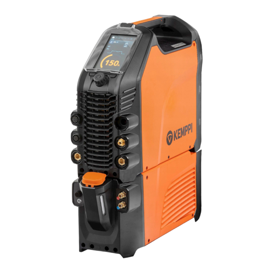
Operating manual - EN 1.1 Equipment description Kemppi MasterTig 235 AC/DC, 325 DC, 335 AC/DC and 425 DC welding equipment is designed for professional industrial use, with characteristics especially suitable for welding materials like aluminum and stainless steel. The equipment con- sists of power source, control panel and cooling unit (optional). - Page 6 The serial number and other device-related identification information may also be saved in the form of a QR code (or a barcode) on the device. Such code can be read by a smartphone camera or with a dedicated code reader device providing fast access to the device-specific information. © Kemppi 1920900 / 2215...
-
Page 7: Installation
MasterTig 325DC and 335ACDC: Provided that the public low voltage short circuit power at the point of common coupling is higher than or equal to the value stated on the list below, this equipment is compliant with IEC 61000-3- 11 and IEC 61000-3-12 and can be connected to public low voltage systems. -
Page 8: Installing Mains Plug
Install the 3-phase plug according to the MasterTig power source and site requirements. In the 1-phase power source (MasterTig 235ACDC) the plug is pre-installed. Refer also to "Technical data" on page 64 for power source specific tech- nical information. © Kemppi 1920900 / 2215... -
Page 9: Installing Control Panel
>> Push the bottom of the panel firmly so that it locks in place. Secure the control panel together with the hinged panel cover in place with the screw provided. The hinged panel cover and the control panel are secured with the same screw. © Kemppi 1920900 / 2215... -
Page 10: Installing Cooling Unit
Secure the power source from the front with the screws provided. Ensure that the cooling unit’s connection cables don't get caught between the units and get damaged in the process. © Kemppi 1920900 / 2215... - Page 11 Fill the cooling unit with cooling liquid. >> MasterTig Cooler M tank volume is 3 litres and the recommended coolant is MPG 4456 (Kemppi mixture). Avoid cooling liquid contact with skin or eyes. In case of an injury, seek for medical advice.
-
Page 12: Installing Particle Filter (Optional)
The optional particle filter is installed together with an additional filter frame as a pack. Place the filter into the filter frame Install the filter pack in front of the air inlet on the rear of the power source. © Kemppi 1920900 / 2215... -
Page 13: Mounting Units On Cart (Optional)
Secure the power source from the front with the screws (2 x M5x12) provided. Do not attempt to move the power source with a hoist from its handle. The handle is meant for manual lifting only. © Kemppi 1920900 / 2215... - Page 14 MasterTig 235ACDC, 325DC, 335ACDC, 425DC Operating manual - EN With the 2 wheel cart (T25MT), an additional securing bracket is attached to the power source handle. Secure the bracket to the cart with the screws provided (M8x16) . © Kemppi 1920900 / 2215...
-
Page 15: Connecting Tig Torch
Connect TIG torch cables and the water cooling inlet and outlet hoses to the units. Secure by turning the con- nectors clockwise. The water cooling connectors are color-coded. Tip: For Kemppi welding torches, refer also to userdoc.kemppi.com. © Kemppi 1920900 / 2215... -
Page 16: Connecting Earth Return Cable And Clamp
Ensure the earth return clamp is secured tightly to the work piece or work surface. Ensure that the clamp's contact surface is as large as possible. DC = MasterTig 325DC and 425DC ACDC = MasterTig 235ACDC and 335ACDC. With the DC power source, in MMA welding only, the earth return cable can also be connected to the negative (-) con- nector, depending on the application. -
Page 17: Connecting Mma Electrode Holder
Ensure that the clamp's contact surface is as large as possible. With the DC power source, in MMA welding only, the cables can also be connected the other way round, depending on the welding polarity. © Kemppi 1920900 / 2215... -
Page 18: Installing Remote Control
Refer to the (+) and (-) signs on the battery holder and in the remote for the correct positioning of batteries. Tools: • Screwdriver, Torx head (T15). Wireless hand remote control (HR45) Take the remote control battery holder out. Install the batteries (3 x AAA) and put the holder back into the remote. © Kemppi 1920900 / 2215... - Page 19 Remote control with cable (HR43, FR43) Connect the remote control cable to the power source. Wireless foot pedal (FR45) Refer to the (+) and (-) signs on the battery holder and in the remote for the correct positioning of batteries. © Kemppi 1920900 / 2215...
- Page 20 Once connected, the blue LED next to the button is lit. The green LED blinks when the battery is low. Tip: You can set minimum and maximum values for the remote current adjustment in the control panel settings. © Kemppi 1920900 / 2215...
-
Page 21: Installing Gas Bottle
A suitable flow rate for argon is normally 5 – 15 l/min. If the gas flow is not correctly set, this will increase the risk of defects in the weld (weld porosity). Spark ignition becomes more difficult if the gas flow is too high. Contact your local Kemppi dealer for choosing the gas and the equipment. Gas bottle valve... -
Page 22: Installing Gas Bottle On Cart
>> With P45MT, tilt the gas bottle back and pull the cart towards the gas bottle and push the top of the gas bottle forwards. The pivot plate assists to lift the bottle into upright position. Secure the gas bottle in place with a strap or a chain. Use the dedicated fixing points in the cart. © Kemppi 1920900 / 2215... -
Page 23: Moving Equipment By Lifting
Ensure that the welding equipment is properly secured to the cart. Connect the 4-legged chain or straps from the hoist hook to the four lifting points on the cart on both sides of the welding equipment. © Kemppi 1920900 / 2215... - Page 24 MasterTig 235ACDC, 325DC, 335ACDC, 425DC Operating manual - EN 2 wheel cart (T25MT): Ensure that the welding equipment is properly secured to the cart. Connect the hoist hook to the lifting handle on the cart. © Kemppi 1920900 / 2215...
-
Page 25: Operation
For troubleshooting, refer to "Troubleshooting" on page 60. Tip: There is a small locker inside the power source handle, under the lid, that can be used for storing small con- sumables. The device QR code can also be found here. © Kemppi 1920900 / 2215... -
Page 26: Operating Power Source
Depending on your control panel type, wait approximately 15 seconds for the system to start up. For control panel operation, refer to: • "Operating control panels MTP23X and MTP33X" on the next page • "Operating control panel MTP35X" on page 36 © Kemppi 1920900 / 2215... -
Page 27: Operating Control Panels Mtp23X And Mtp33X
Long press switches to DC+ mode 5. Ignition mode selection button • Switches between different ignition modes: Lift TIG / High frequency (HF) ignition 6. Trigger logic selection button • Switches between the trigger logics: 2T / 4T © Kemppi 1920900 / 2215... - Page 28 In error situations, an error code is displayed. Refer to "Troubleshooting" on page 60 for more information on the error in question. For welding process and control panel feature descriptions, refer to "Welding processes and features" on page 75. © Kemppi 1920900 / 2215...
-
Page 29: Home
3.2.2 Start & stop sequence The parameters diagram tool makes base parameter identification and setting easy. From pre-gas time to post-gas time and everything in between, you can quickly select and adjust the parameter value. © Kemppi 1920900 / 2215... - Page 30 Min/Max = 0.0 s ... 9.9 s, Auto, 0.1 s step This adjustment is not available when the (Default = Auto) Lift TIG ignition is turned on. Upslope Min/Max = 0.0 s ... 5.0 s, 0.1 s step (Default = 0.0 s) © Kemppi 1920900 / 2215...
- Page 31 10 % ... 70 %, 1 % step (Default = 20 %), Base current amperes visible * Pulse frequency (DC): 0.2 Hz ... 300 Hz, 1 Hz step (0.2 Hz ... 10 Hz step is 0.1 Hz) (Default = 1 Hz) * © Kemppi 1920900 / 2215...
-
Page 32: Settings
Close the parameter setting by pressing the control knob button (1). To enter advanced Settings menu: Press the Settings button (10) for 5 seconds. Rarely used settings items are hidden by default. Those are available in the advanced settings menu. © Kemppi 1920900 / 2215... - Page 33 (use 24 h format). Once the hour is set, press the control knob button to set the minutes. Language Select language from the list Time counter Total arc time and power on time © Kemppi 1920900 / 2215...
- Page 34 Resets to TIG, DC-, 50 A, HF, Pulse OFF (other values as per default). Once the factory reset is complete, the power source must be restarted manually. * Current range adjustable by welder in TIG welding: © Kemppi 1920900 / 2215...
- Page 35 8 A ... 255 A, 1 A step (MasterTig 325, 335) • 8 A ... 355 A, 1 A step (MasterTig 425) • Default = 10 A ... MMA maximum current of the power source. "Welding processes and features" on page 75 © Kemppi 1920900 / 2215...
-
Page 36: Operating Control Panel Mtp35X
Refer also to "Troubleshooting" on page 60 section in this manual for more information on solving error situations. For welding process and control panel feature descriptions, refer to "Welding processes and features" on page 75. Control panel views: • "Home view" on the next page • "Weld Assist view" on page 38 © Kemppi 1920900 / 2215... -
Page 37: Home View
Selected trigger logic, ignition mode, remote mode and welding process • Warning and notification symbols. Welding process (TIG/MMA) Trigger logic (2T/4T) Ignition mode (Lift TIG ignition) Wireless remote and its battery status Remote mode (ON/OFF). © Kemppi 1920900 / 2215... -
Page 38: Weld Assist View
The Weld Assist feature is available for both TIG and MMA welding. In Weld Assist, the selections are made with the con- trol knob (1) and with the two function buttons (2, 3): © Kemppi 1920900 / 2215... - Page 39 >> The welding joint type: butt joint / corner joint / edge joint / lap joint / fillet joint / tube joint / tube+plate joint. >> The welding position: PA / PB / PC / PD / PE / PF / PG. © Kemppi 1920900 / 2215...
- Page 40 Weld Assist automatically sets the following parameters for you: • Current mode: AC / DC- • Current: Depends on the machine used • Pulse (if used): Frequency • AC and Start & stop parameters: Set to default. © Kemppi 1920900 / 2215...
- Page 41 >> The electrode type: Fe-Basic / Fe-Rutile / High Eff. / Ss (stainless steel)/Inox. >> The electrode diameter (1.6 ... 6 mm). >> The welding joint type: butt joint / corner joint / lap joint / fillet joint / tube joint / tube+plate joint. © Kemppi 1920900 / 2215...
- Page 42 • Arc break • DC+ indicates polarity (in this case the electrode holder is connected to the positive (+) DIX connector). All these parameters can still be modified as per normal for the actual welding. © Kemppi 1920900 / 2215...
-
Page 43: Memory Channels View
3.3.4 Start & stop sequence view The parameters diagram view makes base parameter identification and setting easy. From pre-gas time to post-gas time and everything in between, you can quickly select and adjust the needed parameter value. © Kemppi 1920900 / 2215... - Page 44 0.0 s ... 10.0 s, Auto, 0.1 s step (Default = Auto) Search arc OFF / 5 % ... 90 %, step 1 % (Default = OFF) Upslope OFF / 0.1 s ... 5.0 s, 0.1 s step (Default = 0.0 © Kemppi 1920900 / 2215...
- Page 45 MicroTack spot count only 1 spot and the spot count para- meter is not visible. 0.1 s ... 30.0 s / AUTO, 0.1 s step (Default = Post gas Auto) "Welding processes and features" on page 75 © Kemppi 1920900 / 2215...
-
Page 46: Pulse View
Pulse frequency is 20 Hz. 10 % ... 70 %, 1 % step (Default = 40 %) Pulse ratio 10 % ... 70 %, 1 % step (Default = 20 %) Pulse base current © Kemppi 1920900 / 2215... -
Page 47: Current Mode View
Maximum pulse current is also limited by the machine spe- cifications. Adjusting one Pulse parameter value has an effect on the other values as well. "Welding processes and features" on page 75 3.3.6 Current mode view © Kemppi 1920900 / 2215... -
Page 48: Settings View
Min/Max = 0.1 s ... 1.0 s, step 0.1 s (Default = 0.6 s) MIX TIG DC level Min/Max = 50 % ... 150 %, step 1 % (Default = 100 %) "Welding processes and features" on page 75 3.3.7 Settings view © Kemppi 1920900 / 2215... - Page 49 30 % ... 150 % / Auto, step 1 % (Default = Auto) 0 ms ... 50 ms / Auto, step 10 ms (Default Positive ignition time = Auto) Negative ignition current (ACDC): 100 % ... 300 % / Auto, Step 1 % (Default = Auto) © Kemppi 1920900 / 2215...
- Page 50 1 s ... 10 s, step 1 s (Default = 5 s) Show Weld Assist ON / OFF (Default = ON) Screen saver Default = Kemppi logo An alternative screen saver image can be used. For more information, refer to "Screen saver" on page 53.
-
Page 51: Info View
Default = MMA maximum current of the power source. "Welding processes and features" on page 75 3.3.8 Info view In the Info view you can see information about the equipment usage as well as software version for example. © Kemppi 1920900 / 2215... - Page 52 Operating manual - EN Included in the Info view: • Usage counters • Error status and error log • Latest welds • Power source type and model • Power source and control panel software versions. © Kemppi 1920900 / 2215...
-
Page 53: Screen Saver
Connect the USB memory stick to the USB connector on the rear side of the control panel. The control panel detects your USB memory stick automatically and shows a list of available images. Always connect and disconnect the USB device in a straight angle to avoid any additional stress to the USB con- nector. © Kemppi 1920900 / 2215... - Page 54 Remove the USB memory stick and install the control panel back in place. Refer to "Installing control panel" on page 9 for more information. To delete a custom screen saver image from the control panel memory, or to use the Kemppi logo instead, go to "Set- tings view" on page 48.
-
Page 55: Operating Cooling Unit
The cooling liquid circulation can be stopped at any time by pressing the cooling liquid circulation button again. If the system does not fill up during 1 minute after the button has been released, the automatic filling stops. © Kemppi 1920900 / 2215... -
Page 56: Remote Control
Tip: The remote control comes equipped with a handy clip for hanging the remote onto your belt. Foot pedal remote control: To adjust the welding current, press the pedal. Tip: To shift the foot pedal position on the floor, use the foot pedal handle. © Kemppi 1920900 / 2215... -
Page 57: Maintenance
Do not use pressure washing devices. Service workshops Kemppi Service Workshops complete the welding system maintenance according to the Kemppi service agreement. The main aspects in the service workshop maintenance procedure are: © Kemppi... - Page 58 Checkup of the power source mains cable and plug • Repair of defective parts and replacement of defective components • Maintenance test • Test and calibration of operation and performance values when needed. Find your closest service workshop at Kemppi website. © Kemppi 1920900 / 2215...
-
Page 59: Disposal
The owner of the equip- ment is obliged to deliver a decommissioned unit to a regional collection center, as per the instructions of local author- ities or a Kemppi representative. By applying these European Directives you improve the environment and human health. -
Page 60: Troubleshooting
The circulation must be at least 0.5 l/min. • Make sure you are using original Kemppi consumable and spare parts. Incorrect spare part materials may also cause overheating. •... - Page 61 MasterTig 235ACDC, 325DC, 335ACDC, 425DC Operating manual - EN • Check that the welding torch is not overheating. • Check that the earth return clamp is properly attached to a clean surface of the workpiece. © Kemppi 1920900 / 2215...
-
Page 62: Error Codes
Power source Power source calibration has been lost. Restart the power source. If problem persists, contact not calibrated Kemppi service. Note: The equipment operation is lim- ited when this error occurs. Too low mains Voltage in mains network is too low. - Page 63 MasterTig 235ACDC, 325DC, 335ACDC, 425DC Operating manual - EN Error Error descrip- Possible reason Proposed action code tion Internal Memory communication failed. Restart welding system. If problem persists, contact memory failure Kemppi service. © Kemppi 1920900 / 2215...
-
Page 64: Technical Data
Operating manual - EN 6. TECHNICAL DATA "Power source MasterTig 235ACDC" on the next page "Power source MasterTig 325DC" on page 67 "Power source MasterTig 335ACDC" on page 69 "Power source MasterTig 425DC" on page 71 "Cooling unit MasterTig Cooler M" on page 73 For ordering codes, see "Ordering codes"... -
Page 65: Power Source Mastertig 235Acdc
230 V, MMA 120 A / 84 % 84 % 24.8 V Idle power 20 W 20 W -20...+40 °C -20...+40 °C Operating temperature range -20...+60 °C -20...+60 °C Storage temperature range EMC class Degree of protection IP23S IP23S © Kemppi 1920900 / 2215... - Page 66 2483.5 MHz, 10 dBm 2483.5 MHz, 10 dBm MTP35X - Remote controls HR45, FR45 Wired communication type Remote Analog Analog CAN BUS Kemppi Remote-Bus Kemppi Remote-Bus 5...11 kV 5...11 kV Arc striking voltage 1.6...5.0 mm 1.6...5.0 mm Stick electrode diameters ø mm...
-
Page 67: Power Source Mastertig 325Dc
MasterTig 235ACDC, 325DC, 335ACDC, 425DC Operating manual - EN 6.2 Power source MasterTig 325DC MASTERTIG 325DC 325DC G 325DC GM Feature Description Value Mains connection cable 3~, 2.5 mm 3~, 2.5 mm 3~, 2.5 mm Mains connection voltage 3~ 50/60 Hz 380...460 V ±10 %... - Page 68 - Control panels MTP23X, power MTP33X, MTP35X - Remote controls HR45, FR45 Analog Analog Analog Wired communication type Remote Kemppi Remote-Bus Kemppi Remote-Bus Kemppi Remote-Bus CAN BUS Arc striking voltage 5...11 kV 5...11 kV 5...11 kV Stick electrode diameters ø mm 1.6...6.0 mm...
-
Page 69: Power Source Mastertig 335Acdc
544 x 205 x 443 mm 544 x 205 x 443 mm Weight without accessories 22.0 kg 22.5 kg 22.5 kg Arc-on signal for relay 24 V / 50 mA 24 V / 50 mA 24 V / 50 mA © Kemppi 1920900 / 2215... - Page 70 - Control panels MTP23X, power MTP33X, MTP35X - Remote controls HR45, FR45 Analog Analog Analog Wired communication type Remote Kemppi Remote-Bus Kemppi Remote-Bus Kemppi Remote-Bus CAN BUS Arc striking voltage 5...11 kV 5...11 kV 5...11 kV Stick electrode diameters ø mm 1.6...6.0 mm...
-
Page 71: Power Source Mastertig 425Dc
Voltage supply for cooling unit 380...460 V Recommended generator power (min) 20 kVA Wireless communication type: Transmitter frequency and 2.4 GHz Bluetooth, 2400-2483.5 MHz, 10 - Control panels MTP23X, MTP33X, MTP35X power - Remote controls HR45, FR45 © Kemppi 1920900 / 2215... - Page 72 Operating manual - EN MASTERTIG 425DC G Feature Description Value Wired communication type Remote Analog CAN BUS Kemppi Remote-Bus Arc striking voltage 5...11 kV Stick electrode diameters ø mm 1.6...7.0 mm TIG welding cable connection type R1/4 Standards IEC60974-1,-3,-10 IEC 61000-3-12 AS 60974.1-2006...
-
Page 73: Cooling Unit Mastertig Cooler M
1.0 A 1max Rated cooling power at 1 l/min 0.9 kW Cooling power at 1.6 l/min 1.0 kW Recommended coolant MPG 4456 (Kemppi mixture) Coolant pressure (max) 0.4 MPa Tank volume 3.0 l Operating temperature range * -20 ... +40 °C -20 ... -
Page 74: Tig Guide Tables
4 / 5 6.5 / 8.0 5…6 4 / 5 / 6 6.5 / 8.0 / 9.5 6…7 6 / 7 9.5 / 11.0 7…8 7 / 8 / 10 11.0 / 12.5 / 16 8…10 © Kemppi 1920900 / 2215... -
Page 75: Welding Processes And Features
TIG welding process, where the welding current alternates between two current levels: base current and pulse current. Only welding current needs to be adjusted and pulse parameters are preset automatically. Used for optimizing the arc characteristics for desired welding applications. © Kemppi 1920900 / 2215... - Page 76 Welding function that uses higher welding current at the start of the weld. After the Hot start period the cur- rent drops to normal welding current level. The values for Hot start current level and its duration are preset manually. This facilitates the start of the weld especially with aluminum materials. © Kemppi 1920900 / 2215...
- Page 77 Used especially for optimizing welding of aluminum mater- ials of dissimilar thicknesses. Manual arc welding process that uses a consumable electrode. The electrode is covered with flux material that protects the weld area from oxidation and contamination. © Kemppi 1920900 / 2215...
- Page 78 The higher current level of the pulse cycle. In TIG welding, its main task is to create weld pool or increase the heat of the weld pool. Pulse frequency Determines how many pulse cycles is created per second (Hz). Pulse ratio Determines how big part of the whole pulse cycle time is spent on pulse current. © Kemppi 1920900 / 2215...
- Page 79 Trigger operation mode of a welding torch. When you press the trigger down in 2T mode, the shielding gas starts to flow and the arc ignites. Hold down the trigger while welding and release it when you want to stop © Kemppi 1920900 / 2215...
- Page 80 A wizard-like utility for easy selection of welding parameters. The utility walks the user step-by-step through the selection of required parameters, presenting the selections in an easily understandable way for a non-tech- nical user. Available in MTP35X control panel in MasterTig product family. © Kemppi 1920900 / 2215...
-
Page 81: Symbols Used
6.8 Symbols used Symbol Description Coolant output Gas input Gas output DPulse (Double pulse) Carbon arc gouging TIG HF ignition TIG Contact ignition TIG Water Cooling TIG Gas Cooling Arc break Pulse Soft Start Hot Start © Kemppi 1920900 / 2215... - Page 82 Crater Fill with Downslope Crater Fill with Downlevel Tail arc Minilog 4T LOG 4T LOG + Minilog MicroTack welding Continuous welding Spot welding Gas test Frequency or Wavelength Base current Pulse current AC Frequency AC Sine AC Square © Kemppi 1920900 / 2215...
- Page 83 Operating manual - EN AC Optima Remote control Remote control in TIG torch Foot pedal High voltage Low voltage Common symbols used in Kemppi documentation: Symbol Description User manual CE mark EMC Class A Electrical and electronic waste High voltage (warning) Protective earth ©...
-
Page 84: Ordering Codes
Power source: 230A AC/DC, generator and multi-voltage use, VRD locked MT235ACDCGMAU MT325DC MasterTig 325DC Power source: 300 A DC MT325DCG MasterTig 325DC G Power source: 300 A DC, generator use MT325DCGAU Power source: 300 A DC, generator use, VRD locked on MT325DCGM MasterTig 325DC GM... -
Page 85: Accessories
Ordering code For water-cooled torch: For gas-cooled torch: Flexlite TXR10 remote, roller switch TXR10W TXR10G Flexlite TXR20 remote, rocker switch TXR20W TXR20G Flexlite TX other accessories (optional) Product Ordering code SP014802 Flexlite TX trigger extension © Kemppi 1920900 / 2215...
Need help?
Do you have a question about the MasterTig 325DC and is the answer not in the manual?
Questions and answers