Kemppi MasterTig 335ACDC Operating Manual
Hide thumbs
Also See for MasterTig 335ACDC:
- Operating manual (77 pages) ,
- Operating manual (82 pages) ,
- Operating manual (85 pages)

Related Manuals for Kemppi MasterTig 335ACDC


Summary of Contents for Kemppi MasterTig 335ACDC
- Page 1 MasterTig 235ACDC, 325DC, 335ACDC Operating manual - EN MasterTig 235ACDC, 325DC, 335ACDC MasterTig Cooler M © Kemppi 1/73 1920900 / 1921...
-
Page 2: Table Of Contents
3.3.4 Start & stop sequence view 3.3.5 Current mode view 3.3.6 Pulse view 3.3.7 Settings view 3.3.8 Info view 3.3.9 Screen saver 3.4 Operating cooling unit 3.5 Remote control 4. Maintenance 4.1 Disposal 5. Troubleshooting © Kemppi 2/73 1920900 / 1921... - Page 3 Operating manual - EN 5.1 Error codes 6. Technical data 6.1 Power source MasterTig 235ACDC 6.2 Power source MasterTig 325DC 6.3 Power source MasterTig 335ACDC 6.4 Cooling unit MasterTig Cooler M 6.5 TIG guide tables 6.6 Welding processes and features 6.7 Symbols used 7.
-
Page 4: Mastertig
While every effort has been made to ensure that the information contained in this guide is accurate and complete, no liability can be accepted for any errors or omissions. Kemppi reserves the right to change the specification of the product described at any time without prior notice. Do not copy, record, reproduce or transmit the contents of this guide without prior permission from Kemppi. -
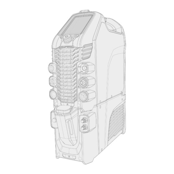
Page 5: Equipment Description
Operating manual - EN 1.1 Equipment description Kemppi MasterTig 235 AC/DC, 325 DC and 335 AC/DC welding equipment is designed for professional industrial use, with characteristics especially suitable for welding materials like aluminum and stainless steel. The equipment con- sists of power source, control panel and cooling unit (optional). The MasterTig Cooler M cooling unit is used in liquid-cooled TIG welding with MasterTig power source. - Page 6 External remote control connector TIG welding cable connector Control cable connector DIX connector (-) DIX connector (+) Coolant liquid inlet and outlet (color-coded) Gas hose connection Mains cable Cooling unit connection Empty holder for unused DIX connector. © Kemppi 6/73 1920900 / 1921...
- Page 7 The serial number and other device-related identification information may also be saved in the form of a QR code (or a barcode) on the device. Such code can be read by a smartphone camera or with a dedicated code reader device providing fast access to the device-specific information. © Kemppi 7/73 1920900 / 1921...
-
Page 8: Installation
According to the EMC classification (Class A), the MasterTig 235, 325 and 335 equipment is not intended to be used in residential locations where the electrical power is provided by the public low-voltage supply system. © Kemppi 8/73 1920900 / 1921... -
Page 9: Installing Mains Plug
>> Insert the top of the panel in the slot first, and then lower the bottom of the panel down. >> Push the bottom of the panel firmly so that it locks in place. © Kemppi 9/73 1920900 / 1921... -
Page 10: Installing Cooling Unit
Do not attempt to move the power source with a hoist from its handle. The handle is meant for manual lifting only. When a transport cart is used, refer also to the "Mounting units on cart (optional)" on page 13 chapter. Tools: • Screwdriver, Torx head (T20). Remove the power source's rear cover. © Kemppi 10/73 1920900 / 1921... - Page 11 Fill the cooling unit with cooling liquid. >> MasterTig Cooler M tank volume is 3 litres and the recommended coolant is MPG 4456 (Kemppi mixture). Avoid cooling liquid contact with skin or eyes. In case of an injury, seek for medical advice.
-
Page 12: Installing Particle Filter (Optional)
The optional particle filter is installed together with an additional filter frame as a pack. Place the filter into the filter frame Install the filter pack in front of the air inlet on the rear of the power source. © Kemppi 12/73 1920900 / 1921... -
Page 13: Mounting Units On Cart (Optional)
Secure the power source from the front with the screws (2 x M5x12) provided. Do not attempt to move the power source with a hoist from its handle. The handle is meant for manual lifting only. © Kemppi 13/73 1920900 / 1921... - Page 14 MasterTig 235ACDC, 325DC, 335ACDC Operating manual - EN With the 2 wheel cart (T25MT), an additional securing bracket is attached to the power source handle. Secure the bracket to the cart with the screws provided (M8x16) . © Kemppi 14/73 1920900 / 1921...
-
Page 15: Connecting Tig Torch
Connect TIG torch cables and the water cooling inlet and outlet hoses to the units. Secure by turning the con- nectors clockwise. The water cooling connectors are color-coded. Tip: For Kemppi welding torches, refer also to userdoc.kemppi.com. © Kemppi 15/73... -
Page 16: Connecting Earth Return Cable And Clamp
DC = MasterTig 325DC ACDC = MasterTig 235ACDC and 335ACDC. With the DC power source, in MMA welding only, the earth return cable can also be connected to the negative (-) con- nector, depending on the application. © Kemppi 16/73 1920900 / 1921... -
Page 17: Connecting Mma Electrode Holder
Ensure that the clamp's contact surface is as large as possible. With the DC power source, in MMA welding only, the cables can also be connected the other way round, depending on the welding polarity. © Kemppi 17/73 1920900 / 1921... -
Page 18: Installing Remote Control
Refer to the (+) and (-) signs on the battery holder and in the remote for the correct positioning of batteries. Tools: • Screwdriver, Torx head (T15). Wireless hand remote control (HR45) Take the remote control battery holder out. Install the batteries (3 x AAA) and put the holder back into the remote. © Kemppi 18/73 1920900 / 1921... - Page 19 Connect the remote control cable to the power source. Wireless foot pedal (FR45) Refer to the (+) and (-) signs on the battery holder and in the remote for the correct positioning of batteries. © Kemppi 19/73 1920900 / 1921...
- Page 20 Once connected, the blue LED next to the button is lit. The green LED blinks when the battery is low. Tip: You can set minimum and maximum values for the remote current adjustment in the control panel set- tings. © Kemppi 20/73 1920900 / 1921...
-
Page 21: Installing Gas Bottle
A suitable flow rate for argon is normally 5 – 15 l/min. If the gas flow is not correctly set, this will increase the risk of defects in the weld (weld porosity). Spark ignition becomes more difficult if the gas flow is too high. Contact your local Kemppi dealer for choosing the gas and the equipment. Gas bottle valve... -
Page 22: Installing Gas Bottle On Cart
>> With P45MT, tilt the gas bottle back and pull the cart towards the gas bottle and push the top of the gas bottle forwards. The pivot plate assists to lift the bottle into upright position. Secure the gas bottle in place with a strap or a chain. Use the dedicated fixing points in the cart. © Kemppi 22/73 1920900 / 1921... -
Page 23: Moving Equipment By Lifting
Ensure that the welding equipment is properly secured to the cart. Connect the 4-legged chain or straps from the hoist hook to the four lifting points on the cart on both sides of the welding equipment. © Kemppi 23/73 1920900 / 1921... - Page 24 MasterTig 235ACDC, 325DC, 335ACDC Operating manual - EN 2 wheel cart (T25MT): Ensure that the welding equipment is properly secured to the cart. Connect the hoist hook to the lifting handle on the cart. © Kemppi 24/73 1920900 / 1921...
-
Page 25: Operation
For troubleshooting, refer to "Troubleshooting" on page 55. Tip: There is a small locker inside the power source handle, under the lid, that can be used for storing small consumables. The device QR code can also be found here. © Kemppi 25/73 1920900 / 1921... -
Page 26: Operating Power Source
Depending on your control panel type, wait approximately 15 seconds for the system to start up. For control panel operation, refer to: • "Operating control panels MTP23X and MTP33X" on page 27 • "Operating control panel MTP35X" on page 35 © Kemppi 26/73 1920900 / 1921... -
Page 27: Operating Control Panels Mtp23X And Mtp33X
Short press switches between current modes: AC / DC- / Mixed current (AC/DC-) • Long press switches to DC+ mode 5. Ignition mode selection button • Switches between different ignition modes: Lift TIG / High frequency (HF) ignition © Kemppi 27/73 1920900 / 1921... - Page 28 Blue: Wireless device is connected • Blue, blinking: Pairing in progress. In error situations, an error code is displayed. Refer to "Troubleshooting" on page 55 section in this manual for more information on the error in question. © Kemppi 28/73 1920900 / 1921...
-
Page 29: Home
To adjust welding current: Press the Home button (11). Turn the control knob (1) to adjust the current. Current (A) is shown on the display. © Kemppi 29/73 1920900 / 1921... -
Page 30: Start & Stop Sequence
The Current mode and Pulse mode selections have an effect on the Start & stop menu contents. Adjustable parameters in continuous welding: Pre gas: Min/Max = 0.0 s ... 9.9 s, Auto, 0.1 s step (Default = Auto) © Kemppi 30/73 1920900 / 1921... - Page 31 Pulse frequency (AC): 0.2 Hz ... 20 Hz, 1 Hz step (0.2 Hz ... 10 Hz step is 0.1 Hz) (Default = 1 Hz) * * Auto Pulse mode has different parameter values and they cannot be adjusted. © Kemppi 31/73...
-
Page 32: Settings
MIX TIG DC level: 50 % ... 150 %, step 1 % (Default = 100 %) MicroTack spot time: 1 ms ... 200 ms, step 1 ms (Default = 10 ms) MicroTack pause time: 50 ms ... 500 ms, step 1 ms (Default = 50 ms) © Kemppi 32/73 1920900 / 1921... - Page 33 Ignition current (DC): 100 % ... 300 % / Auto, step 1 % (Default = Auto) Positive ignition time: 0 ms ... 50 ms / Auto, step 10 ms (Default = Auto) Negative ignition time (AC/DC): 0 ms ... 950 ms / Auto, step 10 ms (Default = Auto) © Kemppi 33/73 1920900 / 1921...
- Page 34 8 A ... 185 A, 1 A step (MasterTig 235) • 8 A ... 255 A, 1 A step (MasterTig 325, 335) • Default = 10 A ... MMA maximum current of the power source. © Kemppi 34/73 1920900 / 1921...
-
Page 35: Operating Control Panel Mtp35X
Refer also to "Troubleshooting" on page 55 section in this manual for more information on solving error situations. For welding process and control panel feature descriptions, refer to "Welding processes and features" on page 66. © Kemppi 35/73 1920900 / 1921... -
Page 36: Home View
Start & stop diagram • Welding mode indicated by the diagram shape: Continuous, Spot or MicroTack • Memory channel used • Selected trigger logic, ignition mode, remote mode and welding process • Warning and notification symbols. © Kemppi 36/73 1920900 / 1921... -
Page 37: Weld Assist View
This is available in the MTP35X control panel. Weld Assist feature is available with TIG welding only. In Weld Assist, the selections are made with the control knob (1) and with the two function buttons (2, 3): © Kemppi 37/73 1920900 / 1921... - Page 38 Tip: You can go back step by step in Weld Assist by pressing the left function button (2). Selecting Cancel with the right function button (3), you can cancel Weld Assist recommendations and return to the beginning. © Kemppi 38/73...
- Page 39 Weld Assist gives you a recommendation for these: • Shielding gas flow: "Argon" + l/min and "Helium" + l/min • Electrode: Diameter • Filler (if used): Material and diameter • Number of passes: Number and/or visualization • Travel speed: mm/min. © Kemppi 39/73 1920900 / 1921...
-
Page 40: Memory Channels View
Turn the control knob (1) to highlight a channel. Open the channel actions menu by pressing the control knob button (1). The available actions are shown: Cancel, Save changes, Save to and Delete. Select the action with the control knob (1). © Kemppi 40/73 1920900 / 1921... -
Page 41: Start & Stop Sequence View
>> This is not available with 4T trigger logic. Minilog level: -99 % ... 125 %, 1 % step (Default = OFF, 0 %) Downslope: OFF / 0.1 s ... 15.0 s (Default = 0.1 s) © Kemppi 41/73 1920900 / 1921... - Page 42 >> If Lift TIG is used, MicroTack graph shows only 1 spot and the spot count parameter is not visible. Post gas: 0.1 s ... 30.0 s / AUTO, 0.1 s step (Default = Auto). © Kemppi 42/73 1920900 / 1921...
-
Page 43: Current Mode View
MIX TIG cycle time: Min/Max = 0.1 s ... 1.0 s, step 0.1 s (Default = 0.6 s) MIX TIG DC level: Min/Max = 50 % ... 150 %, step 1 % (Default = 100 %). © Kemppi 43/73 1920900 / 1921... -
Page 44: Pulse View
Pulse current: 10 A ... 300 A, 1 A step >> These values depend also on other pulse parameters. Maximum pulse current is also limited by the machine specifications. Adjusting one Pulse parameter value has an effect on the other values as well. © Kemppi 44/73 1920900 / 1921... -
Page 45: Settings View
Remote control max: Min = “Current limit min”, Max = “Current limit max” Button remote channel control: OFF / ON (Default = OFF) Wireless remote: Pairing starts automatically when selected >> New pairing information replaces the old information. © Kemppi 45/73 1920900 / 1921... - Page 46 Cooler flow watch: OFF / ON (Default = ON) Brightness: 10 % ... 100 %, step 1 % (Default = 100 %) Weld data time: 1 s ... 10 s, step 1 s (Default = 5 s) Screen saver: Default = Kemppi logo © Kemppi 46/73...
- Page 47 8 A ... 85 A, 1 A step (MasterTig 235, limited supply mode) • 8 A ... 185 A, 1 A step (MasterTig 235) • 8 A ... 255 A, 1 A step (MasterTig 325, 335) • Default = MMA maximum current of the power source. © Kemppi 47/73 1920900 / 1921...
-
Page 48: Info View
In the Info view you can see information about the equipment usage as well as software version for example. Included in the Info view: • Usage counters • Error status and error log • Latest welds • Power source type and model • Power source and control panel software versions. © Kemppi 48/73 1920900 / 1921... -
Page 49: Screen Saver
Connect the USB memory stick to the USB connector on the rear side of the control panel. The control panel detects your USB memory stick automatically and shows a list of available images. Always connect and disconnect the USB device in a straight angle to avoid any additional stress to the USB connector. © Kemppi 49/73 1920900 / 1921... - Page 50 Remove the USB memory stick and install the control panel back in place. Refer to "Installing control panel" on page 9 for more information. To delete a custom screen saver image from the control panel memory, or to use the Kemppi logo instead, go to "Set- tings view" on page 45.
-
Page 51: Operating Cooling Unit
The cooling liquid circulation can be stopped at any time by pressing the cooling liquid circulation button again. If the system does not fill up during 1 minute after the button has been released, the automatic filling stops. © Kemppi 51/73... -
Page 52: Remote Control
Tip: The remote control comes equipped with a handy clip for hanging the remote onto your belt. Foot pedal remote control: To adjust the welding current, press the pedal. Tip: To shift the foot pedal position on the floor, use the foot pedal handle. © Kemppi 52/73 1920900 / 1921... -
Page 53: Maintenance
Check that all covers and components are intact. • Check all the cables and connectors. Do not use them if they are damaged. For repairs, contact Kemppi at www.kemppi.com or your dealer. Periodic maintenance Only an authorized electrician is allowed to carry out electrical work. -
Page 54: Disposal
The owner of the equipment is obliged to deliver a decommissioned unit to a regional collection center, as per the instructions of local authorities or a Kemppi representative. By applying these European Directives you improve the environment and human health. -
Page 55: Troubleshooting
5. TROUBLESHOOTING The problems and the possible causes listed are not definitive, but suggest some typical situations that may turn up during normal use of the welding system. For further information and assistance, contact your nearest Kemppi service workshop. If you have received an error code, refer also to "Error codes" on the next page . -
Page 56: Error Codes
Too long welding session with high power or Do not turn off the cooler. Let the liquid circulate until the overheated high ambient temperature. fans cool it down. If fans are not running, contact Kemppi service. Cooling liquid No cooling liquid or circulation is blocked. - Page 57 Operating manual - EN Open circuit voltage exceeds the VRD limit. Restart the power source. If problem persists, contact VRD error Kemppi service. Torch cooling Water cooled torch is connected but the Turn the cooler on in the settings menu or change the required cooler is turned off.
-
Page 58: Technical Data
6. TECHNICAL DATA "Power source MasterTig 235ACDC" below "Power source MasterTig 325DC" on page 60 "Power source MasterTig 335ACDC" on page 62 "Cooling unit MasterTig Cooler M" on page 64 For ordering codes, see "Ordering codes" on page 72. 6.1 Power source MasterTig 235ACDC... - Page 59 2483.5 MHz, 10 dBm 2483.5 MHz, 10 dBm MTP35X - Remote controls HR45, FR45 Wired communication type Remote Analog Analog CAN BUS Kemppi Remote-Bus Kemppi Remote-Bus Arc striking voltage 5...11 kV 5...11 kV Stick electrode diameters ø mm 1.6...5.0 mm 1.6...5.0 mm...
-
Page 60: Power Source Mastertig 325Dc
IP23S Degree of protection External dimensions LxWxH 544 x 205 x 443 mm 544 x 205 x 443 mm 544 x 205 x 443 mm Weight without accessories 21.0 kg 21.5 kg 21.5 kg © Kemppi 60/73 1920900 / 1921... - Page 61 MTP33X, MTP35X - Remote controls HR45, FR45 Wired communication type Remote Analog Analog Analog CAN BUS Kemppi Remote-Bus Kemppi Remote-Bus Kemppi Remote-Bus Arc striking voltage 5...11 kV 5...11 kV 5...11 kV 1.6...6.0 mm 1.6...6.0 mm 1.6...6.0 mm Stick electrode diameters ø...
-
Page 62: Power Source Mastertig 335Acdc
MasterTig 235ACDC, 325DC, 335ACDC Operating manual - EN 6.3 Power source MasterTig 335ACDC MASTERTIG 335ACDC 335ACDC G 335ACDC GM Feature Description Value Mains connection cable 3~, 2.5 mm 3~, 2.5 mm 3~, 2.5 mm 380...460 V 380...460 V 220…230 V; 380...460... - Page 63 MTP33X, MTP35X - Remote controls HR45, FR45 Wired communication type Remote Analog Analog Analog CAN BUS Kemppi Remote-Bus Kemppi Remote-Bus Kemppi Remote-Bus Arc striking voltage 5...11 kV 5...11 kV 5...11 kV 1.6...6.0 mm 1.6...6.0 mm 1.6...6.0 mm Stick electrode diameters ø...
-
Page 64: Cooling Unit Mastertig Cooler M
Maximum rated supply current 1max Rated cooling power at 1 l/min 0.9 kW Cooling power at 1.6 l/min 1.0 kW Recommended coolant MPG 4456 (Kemppi mixture) Coolant pressure (max) 0.4 MPa 3.0 l Tank volume Operating temperature range * -20 ... +40 °C Storage temperature range -20 ... -
Page 65: Tig Guide Tables
4 / 5 6.5 / 8.0 5…6 4 / 5 / 6 6.5 / 8.0 / 9.5 6…7 6 / 7 9.5 / 11.0 7…8 7 / 8 / 10 11.0 / 12.5 / 16 8…10 © Kemppi 65/73 1920900 / 1921... -
Page 66: Welding Processes And Features
Welding function that uses higher welding current at the start of the weld. After the Hot start period the current drops to normal welding current level. The values for Hot start current level and its duration are preset manually. This facilitates the start of the weld especially with aluminum materials. © Kemppi 66/73 1920900 / 1921... - Page 67 TIG welding process, where the welding current changes between two current levels: base current and pulse current. Parameters can be set either manually or automatically. Used for optimizing the arc characteristics for desired welding applications. © Kemppi 67/73 1920900 / 1921...
- Page 68 A safety device used in welding equipment to reduce the open-circuit voltage to maintain below a certain voltage value. This reduces the risk of electric shock particularly in dangerous environments, such as closed or damp spaces. VRD may also be required by law in certain countries or regions. © Kemppi 68/73 1920900 / 1921...
-
Page 69: Symbols Used
6.7 Symbols used Symbol Description Coolant output Gas input Gas output 1-MIG DPulse (Double pulse) Carbon arc gouging TIG HF ignition TIG Contact ignition TIG Water Cooling TIG Gas Cooling Pulse Soft Start Hot Start © Kemppi 69/73 1920900 / 1921... - Page 70 Crater Fill with Downlevel Tail arc Minilog 4T LOG 4T LOG + Minilog MicroTack welding Continuous welding Spot welding Gas test Frequency or Wavelength Base current Pulse current AC Frequency AC Sinus AC Square © Kemppi 70/73 1920900 / 1921...
- Page 71 Operating manual - EN AC Optima Remote control Remote control in TIG torch Foot pedal High voltage Low voltage Common symbols used in Kemppi documentation: Symbol Description User manual CE mark EMC Class A Electrical and electronic waste High voltage (warning) Protective earth ©...
-
Page 72: Ordering Codes
Power source: 300 A DC, generator and multi-voltage use MT325DCGM MT335ACDC MasterTig 335ACDC Power source: 300 A AC/DC MasterTig 335ACDC G Power source: 300 A AC/DC, generator use MT335ACDCG MT335ACDCGAU Power source: 300 A AC/DC, generator use, VRD locked on... -
Page 73: Accessories
Ordering code For water-cooled torch: For gas-cooled torch: TXR10W TXR10G Flexlite TXR10 remote, roller switch Flexlite TXR20 remote, rocker switch TXR20W TXR20G Flexlite TX other accessories (optional) Product Ordering code Flexlite TX trigger extension SP014802 © Kemppi 73/73 1920900 / 1921...
Need help?
Do you have a question about the MasterTig 335ACDC and is the answer not in the manual?
Questions and answers
About the connection of the single phase,because it has a 3 phase connection.