
Related Manuals for Fujitsu AIRSTAGE J-II


Summary of Contents for Fujitsu AIRSTAGE J-II
- Page 1 Small VRF system for light commercial and home use DTV_J2E015E_09 DESIGN & TECHNICAL MANUAL...
- Page 2 CONTENTS 1. GENERAL INFORMATION 2. MODEL SELECTION 3. OUTDOOR UNITS 4. INDOOR UNITS 5. CONTROL SYSTEM 6. SYSTEM DESIGN 7. FUNCTION SETTING 8. EXTERNAL INPUT & OUTPUT 9. NOTES 10. OPTIONAL PARTS...
- Page 3 1. GENERAL INFORMATION DTV_J2E015E_09--CHAPTER01 2015.01.16...
-
Page 4: Table Of Contents
CONTENTS 1. GENERAL INFORMATION FEATURES OF SYSTEM ............01 - 01 1-1. HIGH ENERGY SAVING ................01 - 01 1-2. MORE COMFORT ..................01 - 04 1-3. MORE CONVENIENCE ................. 01 - 05 1-4. MORE DESIGN FLEXIBILITY ............... 01 - 07 1-5. -
Page 5: Features Of System
Aiming at energy saving performance matched to actual operation, Fujitsu General has developed a high intermediate performance air conditioner corresponding not only to the rated performance at 100% load, but also to low to medium load... - Page 6 ADVANCED HIGH EFFICIENCY TECHNOLOGY „ „ Large propeller fan DC inverter control High performance and low noise Efficiency is improved by realized by large propeller and mounting of new active filter optimization of angle. module. DC fan motor Miniaturized, low noise, high efficiency, multi-stage DC fan motor is mounted.
- Page 7 OPERATION PERFORMANCE IS EFFICIENTLY CONTROLLED „ „ Room temperature set point limitation Economy operation „ „ The minimum and maximum temperature range The temperature setting is offset automatically can be set. over a certain period of time. Set Temp. Heating Cooling (°C) Down...
-
Page 8: More Comfort
1-2. MORE COMFORT POWERFUL HEATING „ „ Heating capacity is improved at low outdoor temperature by our advanced technology. J-II series (6HP) 16.6 Current model (6HP class) Outdoor temperature (°C) LOW NOISE DESIGN „ „ Low noise design of outdoor unit Low noise mode „... -
Page 9: More Convenience
Controller UTY-DTG* Max. controllable 400 indoor units System Controller (Software) UTY-APGX Max. controllable 1,600 indoor units G*: GY (FUJITSU), GG (GENERAL) Control system composition example VRF network system Building control computer Central Remote Controller Network Convertor for L ® ORKS... - Page 10 • Max. controllable 18 indoor units UTY-RSK* UTY-RHK* With operation mode Without operation mode K*: KY (FUJITSU), KYT (FUJITSU), KG (GENERAL) H*: HY (FUJITSU), HG (GENERAL) G*: GY (FUJITSU), GG (GENERAL) G*: RY (FUJITSU), RG (GENERAL) Control system composition example Central...
-
Page 11: More Design Flexibility
1-4. MORE DESIGN FLEXIBILITY LONG PIPING LENGTH „ „ Our advanced refrigerant control technology allows us to achieve a total refrigerant piping length of 180 m. This opens up new possibilities in system design. Actual piping length Height difference between outdoor and indoor units m max. -
Page 12: Easy Installation
1-5. EASY INSTALLATION EASIER INSTALLATION „ „ Easy piping connection „ Improvement of the reliability by decreasing the flare connection. J-II series Flare connection Previous model EV kit Flare connection Terminal box Power supply (Indoor ) Power supply cable Power supply (Outdoor ) Easy wiring connection „... -
Page 13: Easy Maintenance
1-6. EASY MAINTENANCE DESIGN FOR EASY MAINTENANCE „ „ Easy to read 7-segment LED Error status can be checked „ „ easily via the indoor unit wired Confirm detail operational and trouble status controller without using specific equipment An error code is displayed on a liquid crystal screen. -
Page 14: Model Line Up
Type Destination Model code Function Model change code Series name AJ : Outdoor unit H: GENERAL (kW) L : Inverter H : J-II Y: FUJITSU A40 : (12.1) (R410A) A45 : (14.0) A54 : (15.5) - (01 - 10) -... -
Page 15: Indoor Unit
2-2. INDOOR UNIT LINE UP (1/2) „ „ Various combinations of types and capacity 52 models, ranging from 1.1kW to 14.0kW. Capacity Low Static Slim Duct/ Medium Pressure Cassette Compact Slim Static Duct/ Cassette Concealed Pressure Model Concealed Floor Duct code Floor 10.0... - Page 16 Model code Function Series name AU: Cassette H: GENERAL A: Standard (kW) G : Inverter H : VRF II AR: Duct Y: FUJITSU B: Compact 04 (1.1) (R410A) (AU) AB: Floor/Ceiling X:Neutral 07 (2.2) or Ceiling brand B: Low Static 09 (2.8)
-
Page 17: Controller
Series name Destination APG: System Controller UTY : Control unit G: GENERAL ALG: System Controller Lite Y: FUJITSU DTG: Touch Panel Controller X:Neutral brand DCG: Central Remote Controller CGG: Group Remote Controller RNR, RLR, RNK: Wired Remote Controller RSK, RHK: Simple Remote Controller... -
Page 18: Adaptor / Convertor / Maintenance Tool
2-4. ADAPTOR / CONVERTOR / MAINTENANCE TOOL Network Convertor Network Convertor for L ORKS ® Model : UTY-VGGXZ1 Model : UTY-VLGX Split type systems can be For connection between VRF controlled from a central network system and a L ® ORKS controller via the convertor. -
Page 19: Branch Kit
2-5. BRANCH KIT Separation Tube Model :UTP-AX090A Liquid Pipe Gas Pipe Header Model : UTR-H0906L Model : UTR-H0908L Liquid Pipe Liquid Pipe Gas Pipe Gas Pipe - (01 - 15) -... -
Page 20: Ev Kit
2-6. EV KIT EV Kit Models : UTR-EV09XB UTR-EV14XB For Compact Wall Mounted type (EEV external type) 2-7. CASSETTE GRILLE Cassette grille Models : UTG-UFYC-W Cassette grille Models : UTG-UGYA-W UTG-UFGC-W UTG-UGGA-W For Compact Cassette type For Cassette type - (01 - 16) -... -
Page 21: Others (Optional Parts)
2-8. OTHERS (optional parts) Flange (Square) Flange (Round) Model : UTD-SF045T Model : UTD-RF204 For Low Static Pressure Duct / Duct type For Low Static Pressure Duct / Duct type 205 x 1,063 ; L=40 (mm) ø195 (ø205) ; L=85 (mm) Long-life Filter Long-life Filter Model : UTD-LF25NA... - Page 22 Panel spacer Wide panel Model : UTG-BGYA-W Model : UTG-AGYA-W Indoor unit 950mm Panel Panel spacer 600mm Panel 600mm IR Receiver Unit IR Receiver Unit Models : UTY-LRHYB1 Models: UTB-YWC UTY-LRHGB1 For all Duct type For Cassette type Remote Sensor Unit Model : UTY-XSZX Thermo-sensor for sensing the temperature of arbitrary place...
- Page 23 External connect kit External connect kit Model: UTY-XWZXZ6 Model : UTY-XWZXZ7 For Indoor unit / For Outdoor unit / RB unit Central remote controller External connect kit External connect kit Model: UTY-XWZXZ8 Model : UTY-XWZXZ9 For Outdoor unit For Central remote controller External connect kit External connect kit Model : UTY-XWZXZA...
-
Page 24: Revision Code
REVISION CODE ABOUT REVISION CODE „ „ The following functions are different according to Revision code. Revision code Remarks None or A ○ Forced stop function *2 Energy saving software ○ UTY-PEGX For Slim duct type only Setting of Auto louver grille ○... - Page 25 2. MODEL SELECTION DTV_J2E015E_09--CHAPTER02 2015.01.16...
- Page 26 CONTENTS 2. MODEL SELECTION 1. MODEL SELECTION PROCEDURE..........02 - 01 2. MODEL LINE UP ................02 - 02 2-1. OUTDOOR UNIT ..................02 - 02 2-2. INDOOR UNIT ................... 02 - 03 2-3. OPTIONAL PARTS..................02 - 04 3. MODEL SELECTION AND CAPACITY CALCULATION ....02 - 06 3-1.
- Page 27 CONTENTS 2. MODEL SELECTION 8. CAPACITY TABLE HEATING (INDOOR UNIT) ......02 - 44 8-1. COMPACT CASSETTE TYPE ..............02 - 44 8-2. CASSETTE TYPE ..................02 - 46 8-3. LOW STATIC PRESSURE DUCT/CONCEALED FLOOR TYPE....02 - 49 8-4. SLIM DUCT/SLIM CONCEALED FLOOR TYPE ........02 - 51 8-5.
-
Page 28: Model Selection Procedure
MODEL SELECTION PROCEDURE See 2-2.MODEL LINE UP (INDOOR UNIT) and 3-1. SELECTION PROCEDURE OF INDOOR UNIT AND Selection of indoor units OUTDOOR UNIT Selection of required optional parts ● Cassette grille for all Cassette type See 2-3.MODEL LINE UP (OPTIONAL PARTS) ●... -
Page 29: Model Line Up
MODEL LINE UP 2-1. OUTDOOR UNIT LINE UP „ „ Capacity (kW) Maximum connectable Indoor unit connectable Model name indoor unit cooling capacity (kW) *1 Cooling Heating 12.1 13.6 AJ A40LALH 5.6 to 15.7 14.0 16.0 AJ A45LALH 7.0 to 18.2 15.5 18.0... - Page 30 Rated capacity (kW) Dimensions Type Model name Remarks Cooling Heating H x W x D (mm) AUXB04GALH AUXB07GALH AUXB09GALH UTG-UFYC-W (FUJITSU) Compact AUXB12GALH 245 x 570 x 570 Cassette UTG-UFGC-W (GENERAL) AUXB14GALH AUXB18GALH AUXB24GALH AUXD18GALH 246 x 840 x 840...
- Page 31 2-3. OPTIONAL PARTS CONTROLLER „ „ Items Model name Remarks System Controller UTY-APGX Option: UTY-PEGX System Controller Lite UTY-ALGX Option: UTY-PLGXA1, UTY-PLGXR1, UTY-PLGXE1 Touch Panel Controller UTY-DTG Central Remote Controller UTY-DCG Group Remote Controller UTY-CGG Wired Remote Controller (Touch panel) UTY-RNR ...
- Page 32 OTHERS „ „ Items Model name Remarks Flange (Square) UTD-SF045T For Low Static Pressure Duct / Duct type Flange (Round) UTD-RF204 For Low Static Pressure Duct / Duct type UTD-LF25NA For Low Static Pressure Duct / Duct type Long-Life Filter UTD-LF60KA For High Static Pressure Duct type UTZ-PX1BBA...
-
Page 33: Outdoor Unit
MODEL SELECTION AND CAPACITY CALCULATION 3-1. SELECTION PROCEDURE OF INDOOR UNIT AND OUTDOOR UNIT Please select indoor units and outdoor unit and make the capacity of each indoor unit be larger than cooling and heating load. Confirm the design indoor and outdoor temperature condition Calculate heat load of each room Select indoor unit to match the heat load for each room preliminarily Calculate the estimated capacity of each indoor units (Refer to 3-2) - Page 34 Select outdoor unit to match the total capacity of indoor units preliminarily (Confirm the rated capacity ratio of indoor and outdoor unit, the number of connectable indoor units within limit) Confirm if the capacity of outdoor unit. Calculate the compensated capacity of outdoor unit (Refer to 3-2) ●...
-
Page 35: Method Of Capacity Calculation
3-2. METHOD OF CAPACITY CALCULATION The capacity calculation method which takes the effects of air temperature, pipe length and frosting/defrosting into consideration is shown below. 1. Calculate the estimated capacity of each indoor unit. (1) Find capacity of indoor unit at rated condition (TCin)r and at design temperature (TCin)d [from 7. -
Page 36: The Example Of Calculation
3-3. THE EXAMPLE OF CALCULATION EXAMPLE 1 „ „ Fig.1 Outline of the system Design conditions: Outdoor unit ● Temperature Indoor : 28°CDB / 20°CWB Outdoor : 35°CDB ● Pipe length : 70m ● Height difference : 20m (Outdoor unit upper side) Pipe length, L=70m Indoor Indoor... - Page 37 1) Equation for capacity calculation of outdoor unit. i) Refer to 4. CAPACIYY TABLE (OUTDOOR UNIT) to find Y and Y using X and X ii) Calculate capacity of outdoor unit using following equation: Y=(Y ) / (X ) (X-X ) + Y (X, Y) Capacity ratio of indoor units to outdoor unit, X (%)
- Page 38 EXAMPLE 2 „ „ Fig.1 Outline of the system Design conditions: Outdoor unit ● Temperature Indoor : 28°CDB / 20°CWB Outdoor : 35°CDB ● Pipe length : 70m ● Height difference : 20m (Outdoor unit upper side) Pipe length, L=70m Indoor Indoor Indoor...
- Page 39 1) Equation for capacity calculation of outdoor unit. i) Refer to 4. CAPACIYY TABLE (OUTDOOR UNIT) to find Y and Y using X and X ii) Calculate capacity of outdoor unit using following equation: Y=(Y ) / (X ) (X-X ) + Y (X, Y) Capacity ratio of indoor units to outdoor unit, X (%)
-
Page 40: Capacity Table Cooling (Outdoor Unit)
CAPACITY TABLE COOLING (OUTDOOR UNIT) COOLING CAPACITY MODEL : AJ „ „ A40LALH Capacity : 12.1 kW (4HP) „ Indoor temperature Outdoor Total rated temperature cooling capacity 20°CDB / 15 °CWB 23°CDB / 16 °CWB 24°CDB / 17 °CWB 26°CDB / 18 °CWB 27°CDB / 19 °CWB 28°CDB / 20 °CWB 30°CDB / 22 °CWB... - Page 41 COOLING CAPACITY MODEL : AJ „ „ A40LALH Capacity : 12.1 kW (4HP) „ Indoor temperature Outdoor Total rated temperature cooling capacity 20°CDB / 15 °CWB 23°CDB / 16 °CWB 24°CDB / 17 °CWB 26°CDB / 18 °CWB 27°CDB / 19 °CWB 28°CDB / 20 °CWB 30°CDB / 22 °CWB 32°CDB / 23 °CWB...
- Page 42 COOLING CAPACITY MODEL : AJ „ „ A45LALH Capacity : 14.0 kW (5HP) „ Indoor temperature Outdoor Total rated temperature cooling capacity 20°CDB / 15 °CWB 23°CDB / 16 °CWB 24°CDB / 17 °CWB 26°CDB / 18 °CWB 27°CDB / 19 °CWB 28°CDB / 20 °CWB 30°CDB / 22 °CWB 32°CDB / 23 °CWB...
- Page 43 COOLING CAPACITY MODEL : AJ „ „ A45LALH Capacity : 14.0 kW (5HP) „ Indoor temperature Outdoor Total rated temperature cooling capacity 20°CDB / 15 °CWB 23°CDB / 16 °CWB 24°CDB / 17 °CWB 26°CDB / 18 °CWB 27°CDB / 19 °CWB 28°CDB / 20 °CWB 30°CDB / 22 °CWB 32°CDB / 23 °CWB...
- Page 44 COOLING CAPACITY MODEL : AJ „ „ A54LALH Capacity : 15.5 kW (6HP) „ Indoor temperature Outdoor Total rated temperature cooling capacity 20°CDB / 15 °CWB 23°CDB / 16 °CWB 24°CDB / 17 °CWB 26°CDB / 18 °CWB 27°CDB / 19 °CWB 28°CDB / 20 °CWB 30°CDB / 22 °CWB 32°CDB / 23 °CWB...
- Page 45 COOLING CAPACITY MODEL : AJ „ „ A54LALH Capacity : 15.5 kW (6HP) „ Indoor temperature Outdoor Total rated temperature cooling capacity 20°CDB / 15 °CWB 23°CDB / 16 °CWB 24°CDB / 17 °CWB 26°CDB / 18 °CWB 27°CDB / 19 °CWB 28°CDB / 20 °CWB 30°CDB / 22 °CWB 32°CDB / 23 °CWB...
-
Page 46: Capacity Table Heating (Outdoor Unit)
CAPACITY TABLE HEATING (OUTDOOR UNIT) HEATING CAPACITY MODEL : AJ „ „ A40LALH Capacity : 13.6 kW (4HP) „ Indoor temperature Indoor temperature Total rated Total rated Outdoor temperature Outdoor temperature cooling capacity cooling capacity 16°CDB 16°CDB 18°CDB 18°CDB 20°CDB 20°CDB 21°CDB 21°CDB... - Page 47 HEATING CAPACITY MODEL : AJ „ „ A40LALH Capacity : 13.6 kW (4HP) „ Indoor temperature Total rated Outdoor temperature cooling capacity 16°CDB 18°CDB 20°CDB 21°CDB 22°CDB 24°CDB 26°CDB of indoor unit (°CDB) (°CWB) -19.3 -20.0 11.0 3.81 11.0 3.92 10.8 4.04 10.5...
- Page 48 HEATING CAPACITY MODEL : AJ „ „ A45LALH Capacity : 16.0 kW (5HP) „ Indoor temperature Indoor temperature Total rated Total rated Outdoor temperature Outdoor temperature cooling capacity cooling capacity 16°CDB 16°CDB 18°CDB 18°CDB 20°CDB 20°CDB 21°CDB 21°CDB 22°CDB 22°CDB 24°CDB 24°CDB 26°CDB...
- Page 49 HEATING CAPACITY MODEL : AJ „ „ A45LALH Capacity : 16.0 kW (5HP) „ Indoor temperature Total rated Outdoor temperature cooling capacity 16°CDB 18°CDB 20°CDB 21°CDB 22°CDB 24°CDB 26°CDB of indoor unit (°CDB) (°CWB) -19.3 -20.0 11.0 3.66 11.0 3.77 10.9 3.89 10.9...
- Page 50 HEATING CAPACITY MODEL : AJ „ „ A54LALH Capacity : 18.0 kW (6HP) „ Indoor temperature Indoor temperature Total rated Total rated Outdoor temperature Outdoor temperature cooling capacity cooling capacity 16°CDB 16°CDB 18°CDB 18°CDB 20°CDB 20°CDB 21°CDB 21°CDB 22°CDB 22°CDB 24°CDB 24°CDB 26°CDB...
- Page 51 HEATING CAPACITY MODEL : AJ „ „ A54LALH Capacity : 18.0 kW (6HP) „ Indoor temperature Total rated Outdoor temperature cooling capacity 16°CDB 18°CDB 20°CDB 21°CDB 22°CDB 24°CDB 26°CDB of indoor unit (°CDB) (°CWB) -19.3 -20.0 11.3 3.84 11.3 3.96 11.3 4.09 11.3...
-
Page 52: Capacity Compensation Coefficient
CAPACITY COMPENSATION COEFFICIENT COMPENSATION COEFFICIENT OF PIPE LENGTH „ „ The tables give the compensation coefficient of pipe length owing to installation position (pipe length, height difference). Pipe length and height difference are the length and the height difference between outdoor unit and indoor unit. Cooling „... -
Page 53: Capacity Table Cooling (Indoor Unit)
CAPACITY TABLE COOLING (INDOOR UNIT) 7-1. COMPACT CASSETTE TYPE COOLING CAPACITY MODEL : AUXB04GALH „ „ Indoor temperature Outdoor temperature 20°CDB / 15 °CWB 23°CDB / 16 °CWB 24°CDB / 17 °CWB 26°CDB / 18 °CWB 27°CDB / 19 °CWB 28°CDB / 20 °CWB 30°CDB / 22 °CWB 32°CDB / 23 °CWB (°CDB) MODEL : AUXB07GALH „... - Page 54 COOLING CAPACITY MODEL : AUXB14GALH „ „ Indoor temperature Outdoor temperature 20°CDB / 15 °CWB 23°CDB / 16 °CWB 24°CDB / 17 °CWB 26°CDB / 18 °CWB 27°CDB / 19 °CWB 28°CDB / 20 °CWB 30°CDB / 22 °CWB 32°CDB / 23 °CWB (°CDB) MODEL : AUXB18GALH „...
- Page 55 7-2. CASSETTE TYPE COOLING CAPACITY MODEL : AUXD18GALH „ „ Indoor temperature Outdoor temperature 20°CDB / 15 °CWB 23°CDB / 16 °CWB 24°CDB / 17 °CWB 26°CDB / 18 °CWB 27°CDB / 19 °CWB 28°CDB / 20 °CWB 30°CDB / 22 °CWB 32°CDB / 23 °CWB (°CDB) MODEL : AUXD24GALH „...
- Page 56 COOLING CAPACITY MODEL : AUXA18GALH „ „ Indoor temperature Outdoor temperature 20°CDB / 15 °CWB 23°CDB / 16 °CWB 24°CDB / 17 °CWB 26°CDB / 18 °CWB 27°CDB / 19 °CWB 28°CDB / 20 °CWB 30°CDB / 22 °CWB 32°CDB / 23 °CWB (°CDB) MODEL : AUXA24GALH „...
- Page 57 COOLING CAPACITY MODEL : AUXA36GALH „ „ Indoor temperature Indoor temperature Outdoor Outdoor temperature temperature 20°CDB / 15 °CWB 23°CDB / 16 °CWB 24°CDB / 17 °CWB 26°CDB / 18 °CWB 27°CDB / 19 °CWB 28°CDB / 20 °CWB 30°CDB / 22 °CWB 32°CDB / 23 °CWB 20°CDB / 15 °CWB 23°CDB / 16 °CWB 24°CDB / 17 °CWB 26°CDB / 18 °CWB 27°CDB / 19 °CWB 28°CDB / 20 °CWB 30°CDB / 22 °CWB 32°CDB / 23 °CWB (°CDB) (°CDB)
- Page 58 7-3. LOW STATIC PRESSURE DUCT/CONCEALED FLOOR TYPE COOLING CAPACITY MODEL : ARXB07GALH „ „ Indoor temperature Outdoor temperature 20°CDB / 15 °CWB 23°CDB / 16 °CWB 24°CDB / 17 °CWB 26°CDB / 18 °CWB 27°CDB / 19 °CWB 28°CDB / 20 °CWB 30°CDB / 22 °CWB 32°CDB / 23 °CWB (°CDB) MODEL : ARXB09GALH „...
- Page 59 COOLING CAPACITY MODEL : ARXB12GALH „ „ Indoor temperature Outdoor temperature 20°CDB / 15 °CWB 23°CDB / 16 °CWB 24°CDB / 17 °CWB 26°CDB / 18 °CWB 27°CDB / 19 °CWB 28°CDB / 20 °CWB 30°CDB / 22 °CWB 32°CDB / 23 °CWB (°CDB) MODEL : ARXB14GALH „...
- Page 60 7-4. SLIM DUCT/SLIM CONCEALED FLOOR TYPE COOLING CAPACITY MODEL : ARXD04GALH „ „ Indoor temperature Outdoor temperature 20°CDB / 15 °CWB 23°CDB / 16 °CWB 24°CDB / 17 °CWB 26°CDB / 18 °CWB 27°CDB / 19 °CWB 28°CDB / 20 °CWB 30°CDB / 22 °CWB 32°CDB / 23 °CWB (°CDB) MODEL : ARXD07GALH „...
- Page 61 COOLING CAPACITY MODEL : ARXD14GALH „ „ Indoor temperature Outdoor temperature 20°CDB / 15 °CWB 23°CDB / 16 °CWB 24°CDB / 17 °CWB 26°CDB / 18 °CWB 27°CDB / 19 °CWB 28°CDB / 20 °CWB 30°CDB / 22 °CWB 32°CDB / 23 °CWB (°CDB) MODEL : ARXD18GALH „...
- Page 62 7-5. MEDIUM STATIC PRESSURE DUCT TYPE COOLING CAPACITY MODEL : ARXA24GBLH „ „ Indoor temperature Outdoor temperature 20°CDB / 15 °CWB 23°CDB / 16 °CWB 24°CDB / 17 °CWB 26°CDB / 18 °CWB 27°CDB / 19 °CWB 28°CDB / 20 °CWB 30°CDB / 22 °CWB 32°CDB / 23 °CWB (°CDB) 4.9+ MODEL : ARXA30GBLH...
- Page 63 7-6. HIGH STATIC PRESSURE DUCT TYPE COOLING CAPACITY MODEL : ARXC36GBTH „ „ Indoor temperature Outdoor temperature 20°CDB / 15 °CWB 23°CDB / 16 °CWB 24°CDB / 17 °CWB 26°CDB / 18 °CWB 27°CDB / 19 °CWB 28°CDB / 20 °CWB 30°CDB / 22 °CWB 32°CDB / 23 °CWB (°CDB) 10.2 11.2...
- Page 64 7-7. FLOOR / CEILING TYPE COOLING CAPACITY MODEL : AB „ „ A12GATH Indoor temperature Outdoor temperature 20°CDB / 15 °CWB 23°CDB / 16 °CWB 24°CDB / 17 °CWB 26°CDB / 18 °CWB 27°CDB / 19 °CWB 28°CDB / 20 °CWB 30°CDB / 22 °CWB 32°CDB / 23 °CWB (°CDB) MODEL : AB „...
- Page 65 7-8. CEILING TYPE COOLING CAPACITY MODEL : AB „ „ A30GATH Indoor temperature Outdoor temperature 20°CDB / 15 °CWB 23°CDB / 16 °CWB 24°CDB / 17 °CWB 26°CDB / 18 °CWB 27°CDB / 19 °CWB 28°CDB / 20 °CWB 30°CDB / 22 °CWB 32°CDB / 23 °CWB (°CDB) 11.3 12.1...
- Page 66 7-9. WALL MOUNTED TYPE (EEV external model) COOLING CAPACITY MODEL : AS „ „ E04GACH Indoor temperature Outdoor temperature 20°CDB / 15 °CWB 23°CDB / 16 °CWB 24°CDB / 17 °CWB 26°CDB / 18 °CWB 27°CDB / 19 °CWB 28°CDB / 20 °CWB 30°CDB / 22 °CWB 32°CDB / 23 °CWB (°CDB) MODEL : AS „...
- Page 67 COOLING CAPACITY MODEL : AS „ „ E12GACH Indoor temperature Outdoor temperature 20°CDB / 15 °CWB 23°CDB / 16 °CWB 24°CDB / 17 °CWB 26°CDB / 18 °CWB 27°CDB / 19 °CWB 28°CDB / 20 °CWB 30°CDB / 22 °CWB 32°CDB / 23 °CWB (°CDB) MODEL : AS „...
- Page 68 7-10. WALL MOUNTED TYPE COOLING CAPACITY MODEL : AS „ „ A04GACH Indoor temperature Outdoor temperature 20°CDB / 15 °CWB 23°CDB / 16 °CWB 24°CDB / 17 °CWB 26°CDB / 18 °CWB 27°CDB / 19 °CWB 28°CDB / 20 °CWB 30°CDB / 22 °CWB 32°CDB / 23 °CWB (°CDB) MODEL : AS „...
- Page 69 COOLING CAPACITY MODEL : AS „ „ A12GACH Indoor temperature Outdoor temperature 20°CDB / 15 °CWB 23°CDB / 16 °CWB 24°CDB / 17 °CWB 26°CDB / 18 °CWB 27°CDB / 19 °CWB 28°CDB / 20 °CWB 30°CDB / 22 °CWB 32°CDB / 23 °CWB (°CDB) MODEL : AS „...
- Page 70 COOLING CAPACITY MODEL : AS „ „ A18GACH Indoor temperature Outdoor temperature 20°CDB / 15 °CWB 23°CDB / 16 °CWB 24°CDB / 17 °CWB 26°CDB / 18 °CWB 27°CDB / 19 °CWB 28°CDB / 20 °CWB 30°CDB / 22 °CWB 32°CDB / 23 °CWB (°CDB) MODEL : AS „...
-
Page 71: Compact Cassette Type
CAPACITY TABLE HEATING (INDOOR UNIT) 8-1. COMPACT CASSETTE TYPE HEATING CAPACITY MODEL : AUXB04GALH „ „ Indoor temperature Outdoor Temperature 16°CDB 18°CDB 20°CDB 21°CDB 22°CDB 24°CDB 26°CDB (°CWB) (°CDB) -19.3 -20.0 -15.0 -16.0 -12.0 -13.0 -9.0 -10.0 -7.0 -8.0 -6.0 -5.0 -3.0 -4.0... - Page 72 HEATING CAPACITY MODEL : AUXB14GALH „ „ Indoor temperature Outdoor Temperature 16°CDB 18°CDB 20°CDB 21°CDB 22°CDB 24°CDB 26°CDB (°CDB) (°CWB) -19.3 -20.0 -16.0 -15.0 -12.0 -13.0 -9.0 -10.0 -8.0 -7.0 -5.0 -6.0 -3.0 -4.0 -1.0 -2.0 -1.0 12.0 10.6 13.5 15.0 MODEL : AUXB18GALH „...
-
Page 73: Cassette Type
8-2. CASSETTE TYPE HEATING CAPACITY MODEL : AUXD18GALH „ „ Indoor temperature Outdoor Temperature 16°CDB 18°CDB 20°CDB 21°CDB 22°CDB 24°CDB 26°CDB (°CDB) (°CWB) -19.3 -20.0 -16.0 -15.0 -12.0 -13.0 -9.0 -10.0 -8.0 -7.0 -5.0 -6.0 -3.0 -4.0 -1.0 -2.0 -1.0 12.0 10.6 13.5... - Page 74 HEATING CAPACITY MODEL : AUXA18GALH „ „ Indoor temperature Indoor temperature Outdoor Temperature Outdoor Temperature 16°CDB 16°CDB 18°CDB 18°CDB 20°CDB 20°CDB 21°CDB 21°CDB 22°CDB 22°CDB 24°CDB 24°CDB 26°CDB 26°CDB (°CDB) (°CDB) (°CWB) (°CWB) -20.0 -20.0 -19.3 -19.3 -15.0 -15.0 -16.0 -16.0 -12.0 -12.0...
- Page 75 HEATING CAPACITY MODEL : AUXA36GALH „ „ Indoor temperature Outdoor Temperature 16°CDB 18°CDB 20°CDB 21°CDB 22°CDB 24°CDB 26°CDB (°CDB) (°CWB) -19.3 -20.0 -16.0 -15.0 -12.0 -13.0 -9.0 -10.0 -8.0 -7.0 -5.0 -6.0 10.3 10.3 10.2 10.2 10.2 10.1 -3.0 -4.0 10.9 10.8 10.8...
-
Page 76: Low Static Pressure Duct/Concealed Floor Type
8-3. LOW STATIC PRESSURE DUCT/CONCEALED FLOOR TYPE HEATING CAPACITY MODEL : ARXB07GALH „ „ Indoor temperature Outdoor Temperature 16°CDB 18°CDB 20°CDB 21°CDB 22°CDB 24°CDB 26°CDB (°CDB) (°CWB) -19.3 -20.0 -15.0 -16.0 -13.0 -12.0 -9.0 -10.0 -7.0 -8.0 -5.0 -6.0 -3.0 -4.0 -1.0 -2.0... - Page 77 HEATING CAPACITY MODEL : ARXB12GALH „ „ Indoor temperature Outdoor Temperature 16°CDB 18°CDB 20°CDB 21°CDB 22°CDB 24°CDB 26°CDB (°CDB) (°CWB) -19.3 -20.0 -16.0 -15.0 -12.0 -13.0 -9.0 -10.0 -8.0 -7.0 -5.0 -6.0 -3.0 -4.0 -1.0 -2.0 -1.0 12.0 10.6 13.5 15.0 MODEL : ARXB14GALH „...
-
Page 78: Slim Duct/Slim Concealed Floor Type
8-4. SLIM DUCT/SLIM CONCEALED FLOOR TYPE HEATING CAPACITY MODEL : ARXD04GALH „ „ Indoor temperature Outdoor Temperature 16°CDB 18°CDB 20°CDB 21°CDB 22°CDB 24°CDB 26°CDB (°CWB) (°CDB) -19.3 -20.0 -15.0 -16.0 -12.0 -13.0 -9.0 -10.0 -7.0 -8.0 -6.0 -5.0 -3.0 -4.0 -1.0 -2.0 -1.0... - Page 79 HEATING CAPACITY MODEL : ARXD14GALH „ „ Indoor temperature Outdoor Temperature 16°CDB 18°CDB 20°CDB 21°CDB 22°CDB 24°CDB 26°CDB (°CDB) (°CWB) -19.3 -20.0 -15.0 -16.0 -12.0 -13.0 -9.0 -10.0 -7.0 -8.0 -5.0 -6.0 -3.0 -4.0 -1.0 -2.0 -1.0 12.0 10.6 15.0 13.5 MODEL : ARXD18GALH „...
-
Page 80: Medium Static Pressure Duct Type
8-5. MEDIUM STATIC PRESSURE DUCT TYPE HEATING CAPACITY MODEL : ARXA24GBLH „ „ Indoor temperature Outdoor Temperature 16°CDB 18°CDB 20°CDB 21°CDB 22°CDB 24°CDB 26°CDB (°CDB) (°CWB) -19.3 -20.0 -16.0 -15.0 -12.0 -13.0 -9.0 -10.0 -8.0 -7.0 -5.0 -6.0 -3.0 -4.0 -1.0 -2.0 -1.0... -
Page 81: High Static Pressure Duct Type
8-6. HIGH STATIC PRESSURE DUCT TYPE HEATING CAPACITY MODEL : ARXC36GBTH „ „ Indoor temperature Outdoor Temperature 16°CDB 18°CDB 20°CDB 21°CDB 22°CDB 24°CDB 26°CDB (°CDB) (°CWB) -19.3 -20.0 -16.0 -15.0 -12.0 -13.0 -9.0 -10.0 -8.0 -7.0 -5.0 -6.0 10.3 10.3 10.2 10.2 10.2... -
Page 82: Floor / Ceiling Type
8-7. FLOOR / CEILING TYPE HEATING CAPACITY MODEL : AB „ „ A12GATH Indoor temperature Outdoor Temperature 16°CDB 18°CDB 20°CDB 21°CDB 22°CDB 24°CDB 26°CDB (°CDB) (°CWB) -19.3 -20.0 -16.0 -15.0 -12.0 -13.0 -9.0 -10.0 -8.0 -7.0 -5.0 -6.0 -3.0 -4.0 -1.0 -2.0 -1.0... -
Page 83: Ceiling Type
8-8. CEILING TYPE HEATING CAPACITY MODEL : AB „ „ A30GATH Indoor temperature Outdoor Temperature 16°CDB 18°CDB 20°CDB 21°CDB 22°CDB 24°CDB 26°CDB (°CDB) (°CWB) -19.3 -20.0 -16.0 -15.0 -12.0 -13.0 -9.0 -10.0 -8.0 -7.0 -5.0 -6.0 -3.0 -4.0 -1.0 -2.0 -1.0 10.6 10.6... -
Page 84: Wall Mounted Type
8-9. WALL MOUNTED TYPE (EEV external model) HEATING CAPACITY MODEL : AS „ „ E04GACH Indoor temperature Outdoor Temperature 16°CDB 18°CDB 20°CDB 21°CDB 22°CDB 24°CDB 26°CDB (°CWB) (°CDB) -19.3 -20.0 -15.0 -16.0 -12.0 -13.0 -9.0 -10.0 -7.0 -8.0 -6.0 -5.0 -3.0 -4.0 -1.0... - Page 85 HEATING CAPACITY MODEL : AS „ „ E12GACH Indoor temperature Outdoor Temperature 16°CDB 18°CDB 20°CDB 21°CDB 22°CDB 24°CDB 26°CDB (°CWB) (°CDB) -19.3 -20.0 -15.0 -16.0 -12.0 -13.0 -9.0 -10.0 -7.0 -8.0 -6.0 -5.0 -3.0 -4.0 -1.0 -2.0 -1.0 12.0 10.6 15.0 13.5 MODEL : AS...
-
Page 86: Wall Mounted Type
8-10. WALL MOUNTED TYPE HEATING CAPACITY MODEL : AS „ „ A04GACH Indoor temperature Outdoor Temperature 16°CDB 18°CDB 20°CDB 21°CDB 22°CDB 24°CDB 26°CDB (°CWB) (°CDB) -19.3 -20.0 -15.0 -16.0 -12.0 -13.0 -9.0 -10.0 -7.0 -8.0 -6.0 -5.0 -3.0 -4.0 -1.0 -2.0 -1.0 12.0... - Page 87 HEATING CAPACITY MODEL : AS „ „ A12GACH Indoor temperature Outdoor Temperature 16°CDB 18°CDB 20°CDB 21°CDB 22°CDB 24°CDB 26°CDB (°CWB) (°CDB) -19.3 -20.0 -15.0 -16.0 -12.0 -13.0 -9.0 -10.0 -7.0 -8.0 -6.0 -5.0 -3.0 -4.0 -1.0 -2.0 -1.0 12.0 10.6 15.0 13.5 MODEL : AS...
- Page 88 HEATING CAPACITY MODEL : AS „ „ A18GACH Indoor temperature Outdoor Temperature 16°CDB 18°CDB 20°CDB 21°CDB 22°CDB 24°CDB 26°CDB (°CDB) (°CWB) -19.3 -20.0 -16.0 -15.0 -12.0 -13.0 -9.0 -10.0 -8.0 -7.0 -5.0 -6.0 -3.0 -4.0 -1.0 -2.0 -1.0 12.0 10.6 13.5 15.0 MODEL : AS...
- Page 89 3. OUTDOOR UNITS DTV_J2E015E_08--CHAPTER03 2014.11.10...
- Page 90 CONTENTS 3. OUTDOOR UNITS SPECIFICATIONS ..............03 - 01 DIMENSIONS ................03 - 02 INSTALLATION SPACE ............03 - 03 3-1. SINGLE OUTDOOR UNIT INSTALLATION ..........03 - 03 3-2. MULTIPLE OUTDOOR UNIT INSTALLATION ..........03 - 04 3-3. OUTDOOR UNITS INSTALLATION IN MULTI ROW ........03 - 04 REFRIGERANT CIRCUIT ............
-
Page 91: Specifications
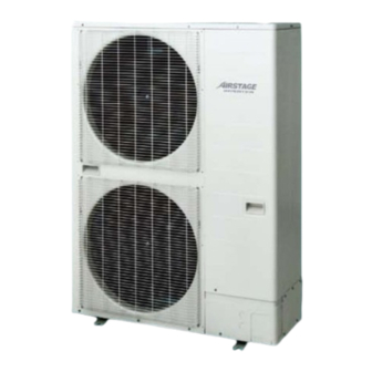
SPECIFICATIONS Nominal system capacity Model name AJ*A40LALH AJ*A45LALH AJ*A54LALH Power source 1 Phase ~ 230V, 50Hz Available voltage range 198 to 264V Cooling 12.1 14.0 15.5 Capacity Heating 13.6 16.0 18.0 Cooling 3.25 3.89 4.49 Input power Heating 3.17 3.81 4.56 Cooling 14.27... -
Page 92: Dimensions
DIMENSIONS MODELS : AJ A40LALH, AJA45LALH, AJA54LALH „ „ (Unit : mm) Top view Front view Rear view Side view Detail A Bottom view - (03 - 02) -... -
Page 93: Installation Space
INSTALLATION SPACE Caution ● The installation space shown in the following examples is based on an ambient temperature under cooling operation of 35 °C DB at the air intake of the outdoor unit. Provide more space around the air intake than shown in the examples if the ambient temperature exceeds 35 °C DB or if the thermal load of all of the outdoor units exceeds the capacity. -
Page 94: Multiple Outdoor Unit Installation
3-2. MULTIPLE OUTDOOR UNIT INSTALLATION Provide at least 25mm of space between the outdoor units if multiple units are installed. ● „ When routing the piping from the side of an outdoor unit, provide space for the piping. ● „ No more than 3 units must be installed side by side. -
Page 95: Refrigerant Circuit
REFRIGERANT CIRCUIT MODELS : AJ A40LALH, AJA45LALH, AJA54LALH „ „ Outdoor unit EEV2 FAN1 FAN2 SCHEX EEV1 HPSW TH10 Indoor unit1 TH21 FAN21 TH23 EEV21 TH22 LIQUID LINE HEX21 GAS LINE Indoor unit2 TH21 FAN21 TH23 EEV21 TH22 HEX21 : Check valve : Strainer : Pressure regulation valve - (03 - 05) -... - Page 96 SYMBOL DESCRIPTION „ „ Outdoor unit „ MARK DESCRIPTION Compressor (Inverter type) Heat exchanger FAN 1 Fan 1 FAN 2 Fan 2 Accumulator Oil separator SCHEX Sub-cool heat exchanger High pressure sensor Low pressure sensor HPSW High pressure sensor switch 4-way valve EEV 1 Electric expansion valve 1 EEV 2 Electric expansion valve 2...
-
Page 97: Wiring Diagram
WIRING DIAGRAM MODELS : AJ A40LALH, AJA45LALH, AJA54LALH „ „ - (03 - 07) -... -
Page 98: Operation Range
OPERATION RANGE Operation range Operation mode Indoor unit Outdoor unit 18 to 32°C DB Cooling / Dry -5 to 46°C DB R.H. 80% or less Heating 10 to 30°C DB -20 to 21°C DB R.H. : Relative Humidity. - (03 - 08) -... -
Page 99: Noise Level Curve
NOISE LEVEL CURVE MODEL : AJ „ „ A40LALH Cooling z Heating „ NC-65 NC-65 NC-60 NC-60 NC-55 NC-55 NC-50 NC-50 NC-45 NC-45 NC-40 NC-40 NC-35 NC-35 NC-30 NC-30 NC-25 NC-25 NC-20 NC-20 NC-15 NC-15 1,000 2,000 4,000 8,000 1,000 2,000 4,000 8,000... - Page 100 MODEL : AJ „ „ A54LALH Cooling z Heating „ NC-65 NC-65 NC-60 NC-60 NC-55 NC-55 NC-50 NC-50 NC-45 NC-45 NC-40 NC-40 NC-35 NC-35 NC-30 NC-30 NC-25 NC-25 NC-20 NC-20 NC-15 NC-15 1,000 2,000 4,000 8,000 1,000 2,000 4,000 8,000 Octave band center frequency, Hz Octave band center frequency, Hz - (03 - 10) -...
- Page 101 SOUND LEVEL CHECK POINT „ „ Air flow Microphone - (03 - 11) -...
-
Page 102: Electric Characteristics
ELECTRIC CHARACTERISTICS Rated Value Electric Characteristics Outdoor Fan Power Supply Full Load Characteristics Wiring Specifications *1 Compressor Motor Limited Power Earth Voltage TOCA Wiring Output Model name Cable Cable Length (m) *2 AJ A40LALH 30.3 29.5 29.5 0.66 AJ A45LALH 30.3 29.5 29.5... -
Page 103: Safety Devices
SAFETY DEVICES Safety device A40LALH A45LALH A54LALH Fuse (Filter PCB) AC 250V 5A Protector (Filter PCB) AC 500V 45A Overcurrent protection Compressor Protector Temperature protection Off : 110°C On : 80°C High Pressure Protection Off : 4.2MPa On : 3.2MPa Low Pressure Protection Off : 0.05MPa... - Page 104 4. INDOOR UNITS DTV_VR2E018E_07--CHAPTER04 2015.01.16...
- Page 105 CONTENTS 4. INDOOR UNITS FEATURES ................04 - 01 1-1. COMPACT CASSETTE TYPE ..............04 - 01 1-2. CASSETTE TYPE..................04 - 02 1-3. LOW STATIC PRESSURE DUCT / CONCEALED FLOOR TYPE ....04 - 03 1-4. SLIM DUCT / SLIM CONCEALED FLOOR TYPE ........04 - 04 1-5.
- Page 106 CONTENTS 4. INDOOR UNITS DIMENSIONS ................04 - 28 4-1. COMPACT CASSETTE TYPE ..............04 - 28 4-2. CASSETTE TYPE..................04 - 30 4-3. LOW STATIC PRESSURE DUCT / CONCEALED FLOOR TYPE ....04 - 33 4-4. SLIM DUCT / SLIM CONCEALED FLOOR TYPE ........04 - 37 4-5.
- Page 107 CONTENTS 4. INDOOR UNITS FAN PERFORMANCE CURVE ..........04 - 135 7-1. LOW STATIC PRESSURE DUCT / CONCEALED FLOOR TYPE ..... 04 - 135 7-2. SLIM DUCT / SLIM CONCEALED FLOOR TYPE ........04 - 140 7-3. MEDIUM STATIC PRESSURE DUCT TYPE ..........04 - 154 7-4.
-
Page 108: Compact Cassette Type
FEATURES 1-1. COMPACT CASSETTE TYPE MODELS : AUXB04GALH, AUXB07GALH, AUXB09GALH, AUXB12GALH, „ „ AUXB14GALH, AUXB18GALH, AUXB24GALH FEATURES „ „ 2-stage turbo fan Quiet quality „ „ High efficiency design by 2 stage structure Optimization of wing form (laminar wing type) and wing number (7 blades 2-stage turbo fan Previous turbo fan Wind... -
Page 109: Cassette Type
1-2. CASSETTE TYPE MODELS : AUXD18GALH, AUXD24GALH, AUXA18GALH,AUXA24GALH, „ „ AUXA30GALH,AUXA34GALH, AUXA36GALH, AUXA45GALH, AUXA54GALH FEATURES „ „ High efficiency turbo fan with 3-dimensional blade „ Previous turbo fan New turbo fan Air passing through the heat High efficiency airflow distribution has exchanger was uneven and the air been achieved by the introduction of a 3 would only flow close to the ceiling. -
Page 110: Low Static Pressure Duct / Concealed Floor Type
1-3. LOW STATIC PRESSURE DUCT / CONCEALED FLOOR TYPE MODELS : ARXB07GALH, ARXB09GALH, ARXB12GALH, „ „ ARXB14GALH, ARXB18GALH Small and compact indoor unit suitable for many applications. FEATURES „ „ Low static Normal mode pressure mode Low noise level „ Air flow drop A low noise level has been achieved for each capacity. -
Page 111: Slim Duct / Slim Concealed Floor Type
1-4. SLIM DUCT / SLIM CONCEALED FLOOR TYPE MODELS : ARXD04GALH, ARXD07GALH, ARXD09GALH, „ „ ARXD12GALH, ARXD14GALH, ARXD18GALH, ARXD24GALH Slim design and wide range of static pressure for flexible installation. FEATURES „ „ Slim design „ Flexible installation „ The slim design allows installations where Ceiling concealed ceilings are narrow. -
Page 112: Medium Static Pressure Duct Type
1-5. MEDIUM STATIC PRESSURE DUCT TYPE MODELS : ARXA24GBLH, ARXA30GBLH, ARXA36GBLH, „ „ ARXA45GBLH Slim compact design allows for easy installation in narrow ceiling spaces up to 270mm. FEATURES „ „ Slim & Compact design 1,135mm „ 1,200 Control box is now included as part of the main chassis In the case of bottom return air connection, not only 270mm... -
Page 113: High Static Pressure Duct Type
1-6. HIGH STATIC PRESSURE DUCT TYPE MODELS : ARXC36GBTH, ARXC45GATH, ARXC60GATH, „ „ ARXC72GBTH, ARXC90GBTH These indoor units allow for high airflow quantities. FEATURES „ „ Easy installation (Compact size & Lightweight) „ Model : ARXC36 Volume 1,250 47.5 1,050 A compact size and do wn lightweight indoor unit has... -
Page 114: Floor / Ceiling Type
1-7. FLOOR / CEILING TYPE MODELS : AB A12GATH, ABA14GATH, ABA18GATH, „ „ ABA24GATH The slim and lightweight design allows the unit to be suspended from the ceiling or installed on the floor. This type suits many room designs. FEATURES „... -
Page 115: Ceiling Type
1-8. CEILING TYPE MODELS : AB A30GATH, ABA36GATH, ABA45GATH, „ „ ABA54GATH Easily concealed in any installation. FEATURES „ „ Installation „ Wall mounted Concealed Open (Field Supplied) General installation Installation pattern Installation which fixes the pattern which where part of the indoor unit to the wall by the use suspends the indoor indoor unit is... -
Page 116: Wall Mounted Type
1-9. WALL MOUNTED TYPE MODELS : AS A04GACH, ASA07GACH, ASA09GACH, „ „ ASA12GACH, ASA14GACH MODELS : AS E04GACH, ASE07GACH, ASE09GACH, „ „ ASE12GACH, ASE14GACH (EEV external model) Compact and Stylish design indoor FEATURES „ „ Filter features „ Apple-catechin filter: Ion deodorization filter Apple-catechin filter Apple-catechin filter uses static... -
Page 117: Wall Mounted Type
1-10. WALL MOUNTED TYPE MODELS : AS A18GACH, ASA24GACH, ASA30GACH „ „ Simple & Elegant Appearance Design FEATURES „ „ Compact & Slim design „ 1120 mm New model Previous model “ Vertical airflow” provides powerful floor level heating „ (24/30) 12 (m) Outside air conditions: 2... -
Page 118: Compact Cassette Type
Connection pipe Gas (Flare) ø 12.70 diameter Drain hose VP25 [ø 25(I.D.) ; ø 32(O.D.)] Model name UTG-UFYC-W(FUJITSU brand); UTG-UFGC-W(GENERAL brand) WHITE Colour Approximate colour of MUNSELL N9.25/ Cassette 50 × 700 × 700 Dimensions grille (H x W x D) Gross 120 ×... - Page 119 Connection pipe Gas (Flare) ø 15.88 diameter Drain hose VP25 [ø 25(I.D.) ; ø 32(O.D.)] Model name UTG-UFYC-W(FUJITSU brand); UTG-UFGC-W(GENERAL brand) WHITE Colour Approximate colour of MUNSELL N9.25/ Cassette 50 × 700 × 700 Dimensions grille (H x W x D) Gross 120 ×...
-
Page 120: Cassette Type
Connection pipe Gas (Flare) ø 15.88 diameter Drain hose VP25 [ø 25(I.D.) ; ø 32(O.D.)] Model name UTG-UGYA-W(FUJITSU brand); UTG-UGGA-W(GENERAL brand) WHITE Colour Approximate colour of MUNSELL N9.25/ Cassette 50 × 950 × 950 Dimensions grille (H x W x D) Gross 115 ×... - Page 121 Connection Gas (Flare) ø 15.88 pipe diameter Drain hose VP25 [ø 25(I.D.) ; ø 32(O.D.)] Model name UTG-UGYA-W(FUJITSU brand); UTG-UGGA-W(GENERAL brand) WHITE Colour Approximate colour of MUNSELL N9.25/ 50 × 950 × 950 Cassette grille Dimensions (H x W x D) Gross 115 ×...
- Page 122 Liquid (Flare) ø 9.52 Connection Gas (Flare) ø 19.05 pipe diameter Drain hose VP25 [ø 25(I.D.) ; ø 32(O.D.)] UTG-UGYA-W(FUJITSU brand); UTG-UGGA- Model name W(GENERAL brand) WHITE Colour Approximate colour of MUNSELL N9.25/ Cassette grille 50 × 950 × 950...
-
Page 123: Low Static Pressure Duct / Concealed Floor Type
2-3. LOW STATIC PRESSURE DUCT / CONCEALED FLOOR TYPE Model name ARXB07GALH ARXB09GALH ARXB12GALH ARXB14GALH ARXB18GALH Power source 230V ~, 50Hz Available voltage range 198 to 264 V Cooling Capacity Heating Input power Static pressure range 0 to 50 Standard static pressure High (103) (122) -
Page 124: Slim Duct / Slim Concealed Floor Type
2-4. SLIM DUCT / SLIM CONCEALED FLOOR TYPE Model name ARXD04GALH ARXD07GALH ARXD09GALH ARXD12GALH ARXD14GALH Power source 230V ~, 50Hz Available voltage range 198 to 264 V Cooling Capacity Heating Input power Static pressure range 0 to 90 Standard static pressure High (142) (153) - Page 125 Model name ARXD18GALH ARXD24GALH Power source 230V ~, 50Hz Available voltage range 198 to 264 V Cooling Capacity Heating Input power Static pressure range 0 to 90 0 to 50 Standard static pressure 1,330 High (261) (369) 1,240 Airflow rate (l / s) (233) (344)
-
Page 126: Medium Static Pressure Duct Type
2-5. MEDIUM STATIC PRESSURE DUCT TYPE Model name ARXA24GBLH ARXA30GBLH ARXA36GBLH ARXA45GBLH Power source 230V ~, 50Hz Available voltage range 198 to 264 V Cooling 11.2 12.5 Capacity Heating 10.0 12.5 14.0 Input power Static pressure range 0 to 150 Standard static pressure 1,280 1,410... -
Page 127: High Static Pressure Duct Type
2-6. HIGH STATIC PRESSURE DUCT TYPE Model name ARXC36GBTH ARXC45GATH ARXC60GATH ARXC72GBTH ARXC90GBTH Power source 230 V ~, 50Hz Available voltage range 198 to 264 V Cooling 11.2 12.5 18.0 22.4 25.0 Capacity Heating 12.5 14.0 20.0 25.0 28.0 Input power Static pressure range 0 to 200 100 to 250... -
Page 128: Floor / Ceiling Type
2-7. FLOOR / CEILING TYPE Model name AB A12GATH AB A14GATH AB A18GATH AB A24GATH Power source 230V ~, 50Hz Available voltage range 198 to 264 V Cooling Capacity Heating Input power 1,000 1,000 High (183) (216) (277) (277) -
Page 129: Ceiling Type
2-8. CEILING TYPE Model name AB A30GATH AB A36GATH AB A45GATH AB A54GATH Power source 230V ~, 50Hz Available voltage range 198 to 264 V Cooling 11.2 12.5 14.0 Capacity Heating 10.0 12.5 14.0 16.0 Input power 1,630 1,690 2,010... - Page 130 2-9. WALL MOUNTED TYPE Model name AS A04GACH AS A07GACH AS A09GACH AS A12GACH AS A14GACH Power source 230V ~, 50Hz Available voltage range 198 to 264 V Cooling Capacity Heating Input power High (125) (136) (139) (156)
- Page 131 2-10. WALL MOUNTED TYPE (EEV external model) Model name AS E04GACH AS E07GACH AS E09GACH AS E12GACH AS E14GACH Power source 230V ~, 50Hz Available voltage range 198 to 264 V Cooling Capacity Heating Input power High (125) (136)
- Page 132 2-11. WALL MOUNTED TYPE Model name AS A18GACH AS A24GACH AS A30GACH Power source 230V ~, 50Hz Available voltage range 198 to 264 V Cooling Capacity Heating Input power 1100 1240 High (233) (305) (343) Airflow rate (l / s) (213) (252)
- Page 133 ELECTRIC CHARACTERISTICS Indoor Unit Power Supply Indoor Rated Frequency Input Power Current Voltage Type Model (Hz) (kW) AUXB04GALH 0.20 0.023 0.17 AUXB07GALH 0.20 0.025 0.17 AUXB09GALH 0.20 0.025 0.17 Compact Cassette AUXB12GALH 230~ 0.24 0.029 0.20 AUXB14GALH 0.29 0.035 0.24 AUXB18GALH 0.30 0.036...
- Page 134 Indoor Unit Power Supply Indoor Rated Frequency Input Power Current Voltage Type Model (Hz) (kW) AS E04GACH 0.20 0.012 0.17 AS E07GACH 0.22 0.015 0.18 Wall Mounted AS E09GACH 230~ 0.23 0.016 0.19 (EEV external Model) AS E12GACH 0.28 0.021 0.23...
- Page 135 DIMENSIONS 4-1. COMPACT CASSETTE TYPE MODELS : AUXB04GALH, AUXB07GALH, AUXB09GALH, AUXB12GALH, „ „ AUXB14GALH, AUXB18GALH, AUXB24GALH (Unit : mm) Hanging bolt position IR receiver Drain hose View A Ceiling Control Box View B View C AUXB04, AUXB07, AUXB09, AUXB18, AUXB24 AUXB12, AUXB14 Liquid...
- Page 136 INSTALLATION PLACE „ „ (Unit : mm) Strong and durable ceiling or more 1,000 1,000 or more or more 1,800 or more Obstruction Floor H (The maximum height from floor to ceiling) (mm) Model name AUXB04/07/09 AUXB12/14/18/24 Standard mode 2,700 2,700 High Ceiling mode 3,000...
- Page 137 4-2. CASSETTE TYPE MODELS : AUXD18GALH, AUXD24GALH „ „ (Unit : mm) IR receiver (Option) Hanging bolt position Drain hose View A (Control Box) Ceiling Wire hole Fresh air inlet (cut out) 70 View B View C AUXD18, AUXD24 Liquid ø...
- Page 138 MODELS : AUXA18GALH, AUXA24GALH, AUXA30GALH, „ „ AUXA34GALH, AUXA36GALH, AUXA45GALH, AUXA54GALH (Unit : mm) IR receiver (Option) Hanging bolt position Drain hose View A (Control Box) Ceiling Wire hole Fresh air inlet (cut out) 70 View B View C AUXA18, AUXA24, AUXA36, AUXA45, AUXA54 AUXA30, AUXA34...
- Page 139 (Unit : mm) INSTALLATION PLACE „ „ Strong and durable ceiling 256 or more (AUXD18,24) 298 or more (AUXA18,24,30,34,36,45,54) 1,500 3,000 or more or more Obstruction 1,800 or more Floor H (The maximum height from floor to ceiling) (mm) Model name AUXD18 AUXD24 AUXA18 AUXA24 AUXA30 AUXA34 AUXA36 AUXA45 AUXA54 Standard mode 3,000...
-
Page 140: Low Static Pressure Duct / Concealed Floor Type
4-3. LOW STATIC PRESSURE DUCT / CONCEALED FLOOR TYPE MODELS : ARXB07GALH, ARXB09GALH „ „ (Unit : mm) Rear view (Floor concealed) View A Rear view (Ceiling concealed) (Drain hose) Side view Top view Drain port Drain port Front view Bottom view ARXB07, ARXB09 Liquid... - Page 141 MODELS : ARXB12GALH, ARXB14GALH, ARXB18GALH „ „ (Unit : mm) Rear view (Floor concealed) (Drain hose) Rear view (Ceiling concealed) View A Side view Top view Drain port Drain port Front view Bottom view ARXB12, ARXB14 ARXB18 Liquid ø 6.35 mm ø...
- Page 142 INSTALLATION PLACE „ „ 1 Strong and durable ceiling (Unit : mm) Indoor unit 1 When drain pump is used, leave the space required for service and Left Right maintenance (Refer to 6-10-1. DRAIN side side PUMP UNIT) ...
- Page 143 BIRD'S-EYE VIEW „ MAINTENANCE SPACE „ „ (Unit : mm) Provide a service access for inspection purposes as shown below. Do not place any wiring or illumination in the service space, as they will impede service. Brackets [Top view] Service space Brackets 400 or more Control...
- Page 144 4-4. SLIM DUCT / SLIM CONCEALED FLOOR TYPE MODELS : ARXD04GALH, ARXD07GALH, ARXD09GALH, „ „ ARXD12GALH, ARXD14GALH (Unit : mm) View A Rear view (Drain hose) Drain port Side view Top view Front view Bottom view ARXD04, ARXD07, ARXD09, ARXD12, ARXD14 Liquid ø...
- Page 145 MODELS : ARXD18GALH „ „ (Unit : mm) Rear view View A (Drain hose) Drain port Top view Side view Front view Bottom view ARXD18 Liquid ø 9.52 mm Refrigerant pipe flare connection ø 15.88 mm Drain hose VP25 [ø...
- Page 146 MODELS : ARXD24GALH „ „ (Unit : mm) View A Rear view (Drain hose) Drain port Top view Side view Front view Bottom view ARXD24 Liquid ø 9.52 mm Refrigerant pipe flare connection ø 15.88 mm Drain hose VP25 [ø...
- Page 147 INSTALLATION PLACE „ „ Strong and durable ceiling (Unit : mm) Indoor unit Left Right side side 400 mm 150 mm or more or more 300 mm or more 20 mm or more 20 mm or more Service hole Ceiling Floor 10mm 10mm...
- Page 148 MAINTENANCE SPACE „ „ (Unit : mm) Provide a service access for inspection purposes as shown below. Do not place any wiring or illumination in the service space, as they will impede service. Service space [Top view] 400 or more Indoor unit Service access - (04 - 41) -...
- Page 149 4-5. MEDIUM STATIC PRESSURE DUCT TYPE MODELS : ARXA24GBLH, ARXA30GBLH, ARXA36GBLH, ARXA45GBLH „ „ (Unit : mm) Front view Side view (R) Side view (L) Top view (Drain hose) Drain port Rear view Drain port ARXA24, ARXA30 ARXA36, ARXA45 Liquid ø...
- Page 150 INSTALLATION PLACE „ „ 1 (Unit : mm) Strong and durable ceiling 1 When drain pump is used, leave the space required for service and maintenance 2 When drain hose is connected, the required dimension is 400mm or more. ...
- Page 151 4-6. HIGH STATIC PRESSURE DUCT TYPE MODELS : ARXC36GBTH, ARXC45GATH, ARXC60GATH „ „ (Unit : mm) Rear view Drain port Side view (R) Side view (L) Top view (Drain hose) Front view ARXC36, ARXC45, ARXC60 Liquid ø 9.52 mm Refrigerant pipe flare connection ø...
- Page 152 INSTALLATION PLACE „ „ (Unit : mm) Strong and durable ceiling MAINTENANCE SPACE „ „ Provide a service access for inspection purposes as shown below. Do not place any wiring or illumination in the service space, as they will impede service. [Top view] Indoor unit 30 or more...
- Page 153 MODELS : ARXC72GBTH, ARXC90GBTH „ „ (Unit : mm) 1587 1410(BOLT PITCH) 1250 150x7=1050 P160x2=320 Φ3 1200 1450 (Drain hose) ARXC72, ARXC90 Liquid ø 12.70 mm Refrigerant pipe flare connection ø 22.22 mm Drain hose VP25 [ø 25mm(I.D.) ; ø 32mm(O.D.)] ...
- Page 154 INSTALLATION PLACE „ „ (a) When service access will be carried out above the indoor unit a recommended installation space (Unit : mm) of 450mm is required. more Service space or more (b) Installation by which service is carried out from the bottom of the unit Service space more...
- Page 155 4-7. FLOOR / CEILING TYPE MODELS : AB A12GATH, ABA14GATH, ABA18GATH, „ „ ABA24GATH (Unit : mm) (Drain hose) AB A12 , AB A14 AB A18 , AB A24 Liquid ø 6.35 mm ø 9.52 mm ...
- Page 156 INSTALLATION PLACE „ „ (Unit : mm) Left Right 300 or more 300 or more Ceiling Ceiling Left Right Indoor unit 2300 150 or more 300 or more 20 or more or more Floor Wall bracket Side of set 100 hole 50 hole 100 hole - (04 - 49) -...
- Page 157 4-8. CEILING TYPE MODELS : AB A30GATH, ABA36GATH, ABA45GATH, „ „ ABA54GATH (Unit : mm) (Drain hose) Drain port Drain port AB A30 AB A36 , AB A45 , AB A54 Liquid ø 9.52 mm ø 9.52 mm ...
- Page 158 INSTALLATION PLACE „ „ (Unit : mm) Ceiling Ceiling panel INDOOR UNIT INDOOR UNIT Ceiling Ceiling panel 80 or more 150 or more 80 or more 150 or more 10 or more 10 or more 2500 2500 or more or more Floor Floor Suspension bolt pitch...
- Page 159 4-9. WALL MOUNTED TYPE MODELS : AS A04GACH, ASA07GACH, ASA09GACH, „ „ ASA12GACH, ASA14GACH 4-10. WALL MOUNTED TYPE (EEV external model) MODELS : AS E04GACH, ASE07GACH, ASE09GACH, „ „ ASE12GACH, ASE14GACH (Unit : mm) AS A04, AS A07, AS A09, AS A12, AS A14 AS ...
- Page 160 INSTALLATION PLACE „ „ (Unit : mm) 50 or more or more or more 1800 or more 1500 or more - (04 - 53) -...
- Page 161 4-11. WALL MOUNTED TYPE MODELS : AS A18GACH, ASA24GACH, ASA30GACH „ „ (Unit : mm) AS A18, AS A24, AS A30 Liquid ø 9.52 mm Refrigerant pipe flare connection ø 15.88 mm I.D. 12 mm , O.D. 16 mm Drain hose ...
- Page 162 INSTALLATION PLACE „ „ (Unit : mm) 60 or more 50 or more 200 or more 1800 or more 1500 or more - (04 - 55) -...
- Page 163 WIRING DIAGRAMS 5-1. COMPACT CASSETTE TYPE MODELS : AUXB04GALH, AUXB07GALH, AUXB09GALH, „ „ AUXB12GALH, AUXB14GALH, AUXB18GALH, AUXB24GALH - (04 - 56) -...
- Page 164 5-2. CASSETTE TYPE MODELS : AUXD18GALH, AUXD24GALH, AUXA18GALH, „ „ AUXA24GALH, AUXA30GALH, AUXA34GALH, AUXA36GALH, AUXA45GALH, AUXA54GALH - (04 - 57) -...
- Page 165 5-3. LOW STATIC PRESSURE DUCT / CONCEALED FLOOR TYPE MODELS : ARXB07GALH, ARXB09GALH, ARXB12GALH, „ „ ARXB14GALH, ARXB18GALH - (04 - 58) -...
-
Page 166: Slim Duct / Slim Concealed Floor Type
5-4. SLIM DUCT / SLIM CONCEALED FLOOR TYPE MODELS : ARXD04GALH, ARXD07GALH, ARXD09GALH, „ „ ARXD12GALH, ARXD14GALH, ARXD18GALH, ARXD24GALH - (04 - 59) -... - Page 167 5-5. MEDIUM STATIC PRESSURE DUCT TYPE MODELS : ARXA24GBLH, ARXA30GBLH, ARXA36GBLH, „ „ ARXA45GBLH - (04 - 60) -...
- Page 168 5-6. HIGH STATIC PRESSURE DUCT TYPE MODELS : ARXC36GBTH „ „ MODELS : ARXC45GATH, ARXC60GATH „ „ - (04 - 61) -...
- Page 169 MODELS : ARXC72GBTH, ARXC90GBTH „ „ - (04 - 62) -...
- Page 170 5-7. FLOOR / CEILING TYPE MODELS : AB A12GATH, ABA14GATH, ABA18GATH, „ „ ABA24GATH - (04 - 63) -...
- Page 171 5-8. CEILING TYPE MODELS : AB A30GATH, ABA36GATH, ABA45GATH, „ „ ABA54GATH - (04 - 64) -...
- Page 172 5-9. WALL MOUNTED TYPE MODELS : AS A04GACH, ASA07GACH, ASA09GACH, „ „ ASA12GACH, ASA14GACH - (04 - 65) -...
- Page 173 5-10. WALL MOUNTED TYPE (EEV external model) MODELS : AS E04GACH, ASE07GACH, ASE09GACH, „ „ ASE12GACH, ASE14GACH - (04 - 66) -...
- Page 174 5-11. WALL MOUNTED TYPE MODELS : AS A18GACH, ASA24GACH, ASA30GACH „ „ - (04 - 67) -...
- Page 175 AIR VELOCITY AND TEMPERATURE DISTRIBUTIONS 6-1. COMPACT CASSETTE TYPE Conditions MODELS : AUXB04GALH Fan speed : High „ „ Operation mode : Fan Voltage : 230V Air velocity distribution „ Top view Vertical airflow direction louver : Up Unit : m/s 0.25 0.25 0.25...
- Page 176 Conditions Fan speed : High Operation mode : Heat Voltage : 230V Air velocity distribution „ Reference Data Side view Vertical airflow direction louver : Down Unit : m/s 0.25 Air temperature distribution „ Side view Vertical airflow direction louver : Down Unit : °C - (04 - 69) -...
- Page 177 Conditions MODELS : AUXB07GALH Fan speed : High „ „ Operation mode : Fan Voltage : 230V Air velocity distribution „ Top view Vertical airflow direction louver : Up Unit : m/s 0.25 0.25 0.25 0.25 Side view Vertical airflow direction louver : Up Unit : m/s 0.25 0.25...
- Page 178 Conditions Fan speed : High Operation mode : Heat Voltage : 230V Air velocity distribution „ Reference Data Side view Vertical airflow direction louver : Down Unit : m/s 0.25 Air temperature distribution „ Side view Vertical airflow direction louver : Down Unit : °C - (04 - 71) -...
- Page 179 Conditions Fan speed : High MODELS : AUXB09GALH „ „ Operation mode : Fan Voltage : 230V Air velocity distribution „ Top view Vertical airflow direction louver : Up Unit : m/s 0.25 0.25 0.25 0.25 Side view Vertical airflow direction louver : Up Unit : m/s 0.25 0.25...
- Page 180 Conditions Fan speed : High Operation mode : Heat Voltage : 230V Air velocity distribution „ Reference Data Side view Vertical airflow direction louver : Down Unit : m/s 0.25 Air temperature distribution „ Side view Vertical airflow direction louver : Down Unit : °C - (04 - 73) -...
- Page 181 Conditions Fan speed : High MODELS : AUXB12GALH „ „ Operation mode : Fan Voltage : 230V Air velocity distribution „ Top view Vertical airflow direction louver : Up Unit : m/s 0.25 0.25 0.25 0.25 Side view Vertical airflow direction louver : Up Unit : m/s 0.25 0.25...
- Page 182 Conditions Fan speed : High Operation mode : Heat Voltage : 230V Air velocity distribution „ Reference Data Side view Vertical airflow direction louver : Down Unit : m/s 0.25 Air temperature distribution „ Side view Vertical airflow direction louver : Down Unit : °C - (04 - 75) -...
- Page 183 Conditions Fan speed : High MODELS : AUXB14GALH „ „ Operation mode : Fan Voltage : 230V Air velocity distribution „ Top view Vertical airflow direction louver : Up Unit : m/s 0.25 0.25 0.25 0.25 Side view Vertical airflow direction louver : Up Unit : m/s 0.25 0.25...
- Page 184 Conditions Fan speed : High Operation mode : Heat Voltage : 230V Air velocity distribution „ Reference Data Side view Vertical airflow direction louver : Down Unit : m/s 0.25 Air temperature distribution „ Side view Vertical airflow direction louver : Down Unit : °C - (04 - 77) -...
- Page 185 Conditions Fan speed : High MODELS : AUXB18GALH „ „ Operation mode : Fan Voltage : 230V Air velocity distribution „ Top view Vertical airflow direction louver : Up Unit : m/s 0.25 0.25 0.25 0.25 Side view Vertical airflow direction louver : Up Unit : m/s 0.25 0.25...
- Page 186 Conditions Fan speed : High Operation mode : Heat Voltage : 230V Air velocity distribution „ Reference Data Side view Vertical airflow direction louver : Down Unit : m/s 0.25 Air temperature distribution „ Side view Vertical airflow direction louver : Down Unit : °C - (04 - 79) -...
- Page 187 Conditions Fan speed : High MODELS : AUXB24GALH „ „ Operation mode : Fan Voltage : 230V Air velocity distribution „ Top view Vertical airflow direction louver : Up Unit : m/s 0.25 0.25 0.25 0.25 Side view Vertical airflow direction louver : Up Unit : m/s 0.25 0.25...
- Page 188 Conditions Fan speed : High Operation mode : Heat Voltage : 230V Air velocity distribution „ Reference Data Side view Vertical airflow direction louver : Down Unit : m/s 0.25 Air temperature distribution „ Side view Vertical airflow direction louver : Down Unit : °C - (04 - 81) -...
- Page 189 6-2. CASSETTE TYPE Conditions MODELS : AUXD18GALH Fan speed : High „ „ Operation mode : Fan Voltage : 230V Air velocity distribution „ Top view Vertical airflow direction louver : Up Unit : m/s Side view Vertical airflow direction louver : Up Unit : m/s - (04 - 82) -...
- Page 190 Conditions Fan speed : High Operation mode : Heat Voltage : 230V Air velocity distribution „ Reference Data Side view Vertical airflow direction louver : Down Unit : m/s 0.25 Air temperature distribution „ Side view Vertical airflow direction louver : Down Unit : °C - (04 - 83) -...
- Page 191 Conditions Fan speed : High MODELS : AUXD24GALH „ „ Operation mode : Fan Voltage : 230V Air velocity distribution „ Top view Vertical airflow direction louver : Up Unit : m/s Side view Vertical airflow direction louver : Up Unit : m/s - (04 - 84) -...
- Page 192 Conditions Fan speed : High Operation mode : Heat Voltage : 230V Air velocity distribution „ Reference Data Side view Vertical airflow direction louver : Down Unit : m/s 0.25 Air temperature distribution „ Side view Vertical airflow direction louver : Down Unit : °C - (04 - 85) -...
- Page 193 Conditions Fan speed : High MODELS : AUXA18GALH, AUXA24GALH „ „ Operation mode : Fan Voltage : 230V Air velocity distribution „ Top view Vertical airflow direction louver : Up Unit : m/s Side view Vertical airflow direction louver : Up Unit : m/s - (04 - 86) -...
- Page 194 Conditions Fan speed : High Operation mode : Heat Voltage : 230V Air velocity distribution „ Reference Data Side view Vertical airflow direction louver : Down Unit : m/s Air temperature distribution „ Side view Vertical airflow direction louver : Down Unit : °C - (04 - 87) -...
- Page 195 Conditions Fan speed : High MODELS : AUXA30GALH „ „ Operation mode : Fan Voltage : 230V Air velocity distribution „ Top view Vertical airflow direction louver : Up Unit : m/s Side view Vertical airflow direction louver : Up Unit : m/s - (04 - 88) -...
- Page 196 Conditions Fan speed : High Operation mode : Heat Voltage : 230V Air velocity distribution „ Reference Data Side view Vertical airflow direction louver : Down Unit : m/s 0.25 Air temperature distribution „ Side view Vertical airflow direction louver : Down Unit : °C - (04 - 89) -...
- Page 197 Conditions Fan speed : High MODELS : AUXA34GALH „ „ Operation mode : Fan Voltage : 230V Air velocity distribution „ Top view Vertical airflow direction louver : Up Unit : m/s Side view Vertical airflow direction louver : Up Unit : m/s - (04 - 90) -...
- Page 198 Conditions Fan speed : High Operation mode : Heat Voltage : 230V Air velocity distribution „ Reference Data Side view Vertical airflow direction louver : Down Unit : m/s 0.25 Side view Vertical airflow direction louver : Down Unit : m/s - (04 - 91) -...
- Page 199 Conditions Fan speed : High MODELS : AUXA36GALH „ „ Operation mode : Fan Voltage : 230V Air velocity distribution „ Top view Vertical airflow direction louver : Up Unit : m/s Side view Vertical airflow direction louver : Up Unit : m/s - (04 - 92) -...
- Page 200 Conditions Fan speed : High Operation mode : Heat Voltage : 230V Air velocity distribution „ Reference Data Side view Vertical airflow direction louver : Down Unit : m/s 0.25 Air temperature distribution „ Side view Vertical airflow direction louver : Down Unit : °C - (04 - 93) -...
- Page 201 Conditions Fan speed : High MODELS : AUXA45GALH „ „ Operation mode : Fan Voltage : 230V Air velocity distribution „ Top view Vertical airflow direction louver : Up Unit : m/s Side view Vertical airflow direction louver : Up Unit : m/s - (04 - 94) -...
- Page 202 Conditions Fan speed : High Operation mode : Heat Voltage : 230V Air velocity distribution „ Reference Data Side view Vertical airflow direction louver : Down Unit : m/s 0.25 Air temperature distribution „ Side view Vertical airflow direction louver : Down Unit : °C - (04 - 95) -...
- Page 203 Conditions Fan speed : High MODELS : AUXA54GALH „ „ Operation mode : Fan Voltage : 230V Air velocity distribution „ Top view Vertical airflow direction louver : Up Unit : m/s Side view Vertical airflow direction louver : Up Unit : m/s - (04 - 96) -...
- Page 204 Conditions Fan speed : High Operation mode : Heat Voltage : 230V Air velocity distribution „ Reference Data Side view Vertical airflow direction louver : Down Unit : m/s 0.25 Air temperature distribution „ Side view Vertical airflow direction louver : Down Unit : °C - (04 - 97) -...
- Page 205 6-3. SLIM DUCT TYPE with Auto louver grille kit MODEL : ARXD04GALH (UTD-GXSA-W) „ „ Note: This data is measured with Auto louver grille kit (Optional parts). Air velocity distribution „ Unit: m/s Top view Vertical airflow direction louver: Up Horizontal airflow direction louver: Center Unit: m/s Top view...
- Page 206 Conditions Fan speed : High Note: This data is measured with Auto louver grille kit (Optional parts). Operation mode : Heat Air velocity distribution Voltage : 230V „ Reference Data Unit: m/s Side view Vertical airflow direction louver: Down Horizontal airflow direction louver: Center Air temperature distribution „...
- Page 207 Conditions MODEL : ARXD07GALH (UTD-GXSA-W) Fan speed : High „ „ Operation mode : Fan Note: This data is measured with Auto louver grille kit (Optional parts). Voltage : 230V Air velocity distribution „ Unit: m/s Top view Vertical airflow direction louver: Up Horizontal airflow direction louver: Center Unit: m/s Top view...
- Page 208 Conditions Fan speed : High Note: This data is measured with Auto louver grille kit (Optional parts). Operation mode : Heat Air velocity distribution Voltage : 230V „ Reference Data Unit: m/s Side view Vertical airflow direction louver: Down Horizontal airflow direction louver: Center Air temperature distribution „...
- Page 209 Conditions MODEL : ARXD09GALH (UTD-GXSA-W) Fan speed : High „ „ Operation mode : Fan Note: This data is measured with Auto louver grille kit (Optional parts). Voltage : 230V Air velocity distribution „ Unit: m/s Top view Vertical airflow direction louver: Up Horizontal airflow direction louver: Center Unit: m/s Top view...
- Page 210 Conditions Fan speed : High Note: This data is measured with Auto louver grille kit (Optional parts). Operation mode : Heat Air velocity distribution Voltage : 230V „ Reference Data Unit: m/s Side view Vertical airflow direction louver: Down Horizontal airflow direction louver: Center Air temperature distribution „...
- Page 211 Conditions MODEL : ARXD12GALH (UTD-GXSA-W) Fan speed : High „ „ Operation mode : Fan Note: This data is measured with Auto louver grille kit (Optional parts). Voltage : 230V Air velocity distribution „ Unit: m/s Top view Vertical airflow direction louver: Up Horizontal airflow direction louver: Center Unit: m/s Top view...
- Page 212 Conditions Fan speed : High Note: This data is measured with Auto louver grille kit (Optional parts). Operation mode : Heat Air velocity distribution Voltage : 230V „ Reference Data Unit: m/s Side view Vertical airflow direction louver: Down Horizontal airflow direction louver: Center Air temperature distribution „...
- Page 213 Conditions MODEL : ARXD14GALH (UTD-GXSA-W) Fan speed : High „ „ Operation mode : Fan Note: This data is measured with Auto louver grille kit (Optional parts). Voltage : 230V Air velocity distribution „ Unit: m/s Top view Vertical airflow direction louver: Up Horizontal airflow direction louver: Center Unit: m/s Top view...
- Page 214 Conditions Fan speed : High Note: This data is measured with Auto louver grille kit (Optional parts). Operation mode : Heat Air velocity distribution Voltage : 230V „ Reference Data Unit: m/s Side view Vertical airflow direction louver: Down Horizontal airflow direction louver: Center Air temperature distribution „...
- Page 215 Conditions MODEL : ARXD18GALH (UTD-GXSB-W) Fan speed : High „ „ Operation mode : Fan Note: This data is measured with Auto louver grille kit (Optional parts). Voltage : 230V Air velocity distribution „ Unit: m/s Top view Vertical airflow direction louver: Up Horizontal airflow direction louver: Center Unit: m/s Top view...
- Page 216 Conditions Fan speed : High Note: This data is measured with Auto louver grille kit (Optional parts). Operation mode : Heat Air velocity distribution Voltage : 230V „ Reference Data Unit: m/s Side view Vertical airflow direction louver : Down Horizontal airflow direction louver : Center Air temperature distribution „...
- Page 217 Conditions MODEL : ARXD24GALH (UTD-GXSC-W) Fan speed : High „ „ Operation mode : Fan Note: This data is measured with Auto louver grille kit (Optional parts). Voltage : 230V Air velocity distribution „ Unit: m/s Top view Vertical airflow direction louver: Up Horizontal airflow direction louver: Center Unit: m/s Top view...
- Page 218 Conditions Fan speed : High Note: This data is measured with Auto louver grille kit (Optional parts). Operation mode : Heat Air velocity distribution Voltage : 230V „ Reference Data Unit: m/s Side view Vertical airflow direction louver: Down Horizontal airflow direction louver: Center Air temperature distribution „...
- Page 219 6-4. FLOOR / CEILING TYPE MODELS : ABA12GATH, ABA14GATH (FLOOR CONSOLE) „ „ Conditions Fan speed : High Operation mode : Fan Voltage : 230V Unit: m/s Top view Vertical airflow direction louver: Down 0.25 Horizontal airflow direction louver: Center Unit: m/s 0.25 Top view...
- Page 220 MODELS : AB A12GATH, ABA14GATH (UNDER CEILING) „ „ Conditions Fan speed : High Operation mode : Fan Voltage : 230V Unit: m/s Top view 0.25 Vertical airflow direction louver: Up Horizontal airflow direction louver: Center Unit: m/s 0.25 HORIZONTAL: Right Top view Vertical airflow direction louver: Up Horizontal airflow direction louver: Right &...
- Page 221 Conditions MODEL : AB A18GATH (FLOOR CONSOLE) Fan speed : High „ „ Operation mode : Fan Voltage : 230V Unit: m/s Top view Vertical airflow direction louver: Down 0.25 Horizontal airflow direction louver: Center Unit: m/s 0.25 HORIZONTAL: Right Top view Vertical airflow direction louver: Down Horizontal airflow direction louver: Right &...
- Page 222 Conditions MODEL : AB A18GATH (UNDER CEILING) Fan speed : High „ „ Operation mode : Fan Voltage : 230V Unit: m/s Top view Vertical airflow direction louver: Up 0.25 Horizontal airflow direction louver: Center Unit: m/s 0.25 HORIZONTAL: Right Top view Vertical airflow direction louver: Up Horizontal airflow direction louver: Right &...
- Page 223 Conditions MODEL : AB A24GATH (FLOOR CONSOLE) Fan speed : High „ „ Operation mode : Fan Voltage : 230V Unit: m/s Top view Vertical airflow direction louver: Down 0.25 Horizontal airflow direction louver: Center Unit: m/s 0.25 HORIZONTAL: Right Top view Vertical airflow direction louver: Down Horizontal airflow direction louver: Right &...
- Page 224 Conditions MODEL : AB A24GATH (UNDER CEILING) Fan speed : High „ „ Operation mode : Fan Voltage : 230V Unit: m/s Top view Vertical airflow direction louver: Up 0.25 Horizontal airflow direction louver: Center Unit: m/s 0.25 HORIZONTAL: Right Top view Vertical airflow direction louver: Up Horizontal airflow direction louver: Right &...
- Page 225 6-5. CEILING TYPE Conditions MODEL : AB Fan speed : High „ „ A30GATH Operation mode : Fan Voltage : 230V Unit : (m / s) ( m ) Top view Vertical airflow direction louver: Up 0.25 Horizontal airflow direction louver: Center ( m ) 0 1 2 3 4 5 6 7 8 9 10 11 12 13 14 15 16 17 18 Unit : (m / s)
- Page 226 Conditions MODEL : AB Fan speed : High „ „ A36GATH Operation mode : Fan Voltage : 230V Unit : (m / s) ( m ) Top view Vertical airflow direction louver: Up 0.25 Horizontal airflow direction louver: Center ( m ) 0 1 2 3 4 5 6 7 8 9 10 11 12 13 14 15 16 17 18 Unit : (m / s) ( m )
- Page 227 Conditions MODEL : AB Fan speed : High „ „ A45GATH Operation mode : Fan Voltage : 230V Unit : (m / s) ( m ) Top view Vertical airflow direction louver: Up 0.25 Horizontal airflow direction louver: Center 0 1 2 3 4 5 6 7 8 9 10 11 12 13 14 15 16 17 18 ( m ) Unit : (m / s) ( m )
- Page 228 MODEL : AB Conditions „ „ A54GATH Fan speed : High Operation mode : Fan Voltage : 230V Top view Vertical airflow direction louver: Up Horizontal airflow direction louver: Center Top view Vertical airflow direction louver: Up Horizontal airflow direction louver: Right & Left Side view Vertical airflow direction louver: Up Horizontal airflow direction louver: Center...
- Page 229 6-6. WALL MOUNTED TYPE Conditions MODEL : AS Fan speed : High „ „ A04GACH Operation mode : Fan Voltage : 230V Unit : m/s Top view 0.25 Vertical airflow direction louver: Up Horizontal airflow direction louver: Center Unit : m/s 0.25 Top view Vertical airflow direction louver: Up...
- Page 230 Conditions Fan speed : High Operation mode : Fan Voltage : 230V Unit : m/s Side view Vertical airflow direction louver: Down Horizontal airflow direction louver: Center 0.25 Conditions Fan speed : High Operation mode : Heat Voltage : 230V Reference Data Unit : °C Side view...
- Page 231 Conditions MODELS : AS A07GACH, ASA09GACH Fan speed : High „ „ Operation mode : Fan Voltage : 230V Unit : m/s Top view 0.25 Vertical airflow direction louver: Up Horizontal airflow direction louver: Center Unit : m/s 0.25 Top view Vertical airflow direction louver: Up Horizontal airflow direction louver: Right &...
- Page 232 Conditions MODEL : AS „ „ A12GACH Fan speed : High Operation mode : Fan Voltage : 230V Unit : m/s Top view Vertical airflow direction louver: Up 0.25 Horizontal airflow direction louver: Center Unit : m/s 0.25 Top view Vertical airflow direction louver: Up Horizontal airflow direction louver: Right &...
- Page 233 Conditions MODEL : AS „ „ A14GACH Fan speed : High Operation mode : Fan Voltage : 230V Unit : m/s Top view Vertical airflow direction louver: Up 0.25 Horizontal airflow direction louver: Center Unit : m/s 0.25 Top view Vertical airflow direction louver : Up Horizontal airflow direction louver: Right &...
- Page 234 6-7. WALL MOUNTED TYPE (EEV external model) Conditions MODEL : AS Fan speed : High „ „ E04GACH Operation mode : Fan Voltage : 230V Unit : m/s Top view 0.25 Vertical airflow direction louver: Up Horizontal airflow direction louver: Center Unit : m/s 0.25 Top view...
- Page 235 Conditions Fan speed : High Operation mode : Fan Voltage : 230V Unit : m/s Side view Vertical airflow direction louver: Down Horizontal airflow direction louver: Center 0.25 Conditions Fan speed : High Operation mode : Heat Voltage : 230V Reference Data Unit : °C Side view...
- Page 236 Conditions MODELS : AS E07GACH, ASE09GACH Fan speed : High „ „ Operation mode : Fan Voltage : 230V Unit : m/s Top view Vertical airflow direction louver: Up 0.25 Horizontal airflow direction louver: Center Unit : m/s 0.25 Top view Vertical airflow direction louver: Up Horizontal airflow direction louver: Right &...
- Page 237 Conditions MODEL : AS „ „ E12GACH Fan speed : High Operation mode : Fan Voltage : 230V Unit : m/s Top view Vertical airflow direction louver: Up 0.25 Horizontal airflow direction louver: Center Unit : m/s 0.25 Top view Vertical airflow direction louver: Up Horizontal airflow direction louver: Right &...
- Page 238 Conditions MODEL : AS „ „ E14GACH Fan speed : High Operation mode : Fan Voltage : 230V Unit : m/s Top view Vertical airflow direction louver: Up 0.25 Horizontal airflow direction louver: Center Unit : m/s 0.25 Top view Vertical airflow direction louver: Up Horizontal airflow direction louver: Right &...
- Page 239 6-8. WALL MOUNTED TYPE Conditions MODEL : AS Fan speed : High „ „ A18GACH Operation mode : Fan Voltage : 230V Unit : m/s Top view Vertical airflow direction louver: Up Horizontal airflow direction louver: Center Unit : m/s Top view Vertical airflow direction louver: Up Horizontal airflow direction louver: Right &...
- Page 240 Conditions MODEL : AS „ „ A24GACH Fan speed : High Operation mode : Fan Voltage : 230V Unit : m/s Top view Vertical airflow direction louver: Up Horizontal airflow direction louver: Center Unit : m/s Top view Vertical airflow direction louver: Up Horizontal airflow direction louver: Right &...
- Page 241 Conditions MODEL : AS „ „ A30GACH Fan speed : High Operation mode : Fan Voltage : 230V Unit : m/s Top view Vertical airflow direction louver: Up Horizontal airflow direction louver: Center Unit : m/s Top view Vertical airflow direction louver: Up Horizontal airflow direction louver: Right &...
- Page 242 FAN PERFORMANCE CURVE 7-1. LOW STATIC PRESSURE DUCT / CONCEALED FLOOR TYPE MODEL : ARXB07GALH „ „ High mode upper limit High mode Hi High mode High mode Lo lower limit Low mode upper limit Low mode Hi Low mode Lo Air Flow [m Cooling Capacity...
- Page 243 MODEL : ARXB09GALH „ „ High mode High mode Hi upper limit High mode High mode Lo lower limit Low mode upper limit Low mode Hi Low mode Lo Air Flow [m Cooling Capacity Outlet Temperature Air Flow [m Heating Capacity Outlet Temperature...
- Page 244 MODEL : ARXB12GALH „ „ High mode Hi High mode upper limit High mode High mode Lo lower limit Low mode upper limit Low mode Hi Low mode Lo Air Flow [m Cooling Capacity Outlet Temperature Air Flow [m Heating Capacity Outlet Temperature...
- Page 245 MODEL : ARXB14GALH „ „ High mode upper limit High mode Hi High mode High mode Lo lower limit Low mode upper limit Low mode Hi Low mode Lo Air Flow [m Cooling Capacity Outlet Temperature Air Flow [m Heating Capacity Outlet Temperature...
- Page 246 MODEL : ARXB18GALH „ „ High mode upper limit High mode Hi High mode High mode Lo lower limit Low mode Low mode Hi upper limit Low mode Lo 1,000 Air Flow [m Cooling Outlet Temperature Capacity 1,000 Air Flow [m Heating Capacity Outlet...
- Page 247 7-2. SLIM DUCT / SLIM CONCEALED FLOOR TYPE MODEL : ARXD04GALH „ „ Cooling „ SP mode09 Hi (SP mode09) upper limit Lo (SP mode09) Med (SP mode09) SP mode09 lower limit Normal SP Hi (Normal SP) upper limit Med (Normal SP) Lo (Normal SP) SP mode00 Normal SP...
- Page 248 Available air flow rate range @ Hi speed Hi (SP mode09) Hi (SP mode08) Hi (SP mode07) Hi (SP mode06) Hi (Normal SP) Hi (SP mode05) Hi (SP mode02) Hi (SP mode04) Hi (SP mode01) Hi (SP mode00) Hi (SP mode03) Air Flow [m *1: Available air flow rate range when Auto louver grille (option) is installed.
- Page 249 MODEL : ARXD07GALH „ „ SP mode09 upper limit Hi (SP mode09) Med (SP mode09) SP mode09 lower limit Lo (SP mode09) Normal SP upper limit Hi (Normal SP) Med (Normal SP) Lo (Normal SP) Normal SP SP mode00 lower limit upper limit Med (SP mode00) Hi (SP mode00)
- Page 250 Cooling Capacity Outlet Temperature Air Flow [m Heating Capacity Outlet Temperature Air Flow [m - (04 - 143) -...
- Page 251 MODEL : ARXD09GALH „ „ SP mode09 Hi (SP mode09) upper limit Med (SP mode09) Lo (SP mode09) SP mode09 lower limit Normal SP Hi (Normal SP) upper limit Med (Normal SP) Lo (Normal SP) SP mode00 upper limit Med (SP mode00) Hi (SP mode00) Lo (SP mode00) Air Flow [m...
- Page 252 Cooling Capacity Outlet Temperature Air Flow [m Heating Capacity Outlet Temperature Air Flow [m - (04 - 145) -...
- Page 253 MODEL : ARXD12GALH „ „ SP mode09 Hi (SP mode09) upper limit Med (SP mode09) Lo (SP mode09) SP mode09 lower limit Normal SP Hi (Normal SP) upper limit Med (Normal SP) SP mode00 upper limit Lo (Normal SP) Med (SP mode00) Hi (SP mode00) Lo (SP mode00) Air Flow [m...
- Page 254 Cooling Capacity Outlet Temperature Air Flow [m Heating Capacity Outlet Temperature Air Flow [m - (04 - 147) -...
- Page 255 MODEL : ARXD14GALH „ „ SP mode09 Hi (SP mode09) upper limit Med (SP mode09) Lo (SP mode09) SP mode09 Normal SP lower limit upper limit Hi (Normal SP) Lo (NormalSP) Med (Normal SP) SP mode00 upper limit Med (SP mode00) Hi (SP mode00) Lo (SP mode00) 1000...
- Page 256 Cooling Capacity Outlet Temperature 1000 Air Flow [m Heating Capacity Outlet Temperature 1000 Air Flow [m - (04 - 149) -...
- Page 257 MODEL : ARXD18GALH „ „ Hi (SP mode09) SP mode09 upper limit Med (SP mode09) Lo (SP mode09) SP mode09 Normal SP lower limit upper limit Hi (Normal SP) Lo (Normal SP) Med (Normal SP) SP mode00 upper limit Hi (SP mode00) Med (SP mode00) Lo (SP mode00) 1000...
- Page 258 Cooling Capacity Outlet Temperature 1000 1100 1200 Air Flow [m Heating Capacity Outlet Temperature 1000 1100 1200 Air Flow [m - (04 - 151) -...
- Page 259 MODEL : ARXD24GALH „ „ SP mode05 upper limit Hi (SP mode05) Normal SP Med (SP mode05) upper limit Med (Normal SP) Lo (SP mode05) Lo (Normal SP) HSP mode05 lower limit SP mode00 upper limit Med (SP mode00) Hi (Normal SP) Lo (SP mode00) Hi (SP mode00) 1000...
- Page 260 Cooling Capacity Outlet Temperature 1000 1100 1200 1300 1400 1500 1600 Air Flow [m Heating Capacity Outlet Temperature 1000 1100 1200 1300 1400 1500 1600 Air Flow [m - (04 - 153) -...
-
Page 261: Medium Static Pressure Duct Type
7-3. MEDIUM STATIC PRESSURE DUCT TYPE MODEL : ARXA24GBLH „ „ Hi (SP mode14) SP mode14 upper limit SP mode14 lower limit Lo (SP mode14) Normal SP Hi (Normal SP) upper limit Lo (Normal SP) Normal SP SP mode00 lower limit upper limit Hi (SP mode00) Lo (SP mode00) - Page 262 Cooling Capacity Outlet Temperature Air Flow [m 1000 1100 1200 1300 1400 1500 Air Flow [m Heating Capacity Outlet Temperature 1000 1100 1200 1300 1400 1500 Air Flow [m - (04 - 155) -...
- Page 263 MODEL : ARXA30GBLH „ „ Hi (SP mode14) SP mode14 upper limit SP mode14 lower limit Lo (SP mode14) Normal SP Hi (Normal SP) upper limit Lo (Normal SP) Normal SP lower limit SP mode00 upper limit Hi (SP mode00) Lo (SP mode00) 1000 1100...
- Page 264 Cooling Capacity Outlet Temperature Air Flow [m 1000 1100 1200 1300 1400 1500 1600 1700 Air Flow [m Heating Capacity Outlet Temperature 1000 1100 1200 1300 1400 1500 1600 1700 Air Flow [m - (04 - 157) -...
- Page 265 MODEL : ARXA36GBLH „ „ Hi (SP mode12) SP mode12 upper limit SP mode12 lower limit Lo (SP mode12) Normal SP upper limit Hi (Normal SP) Lo (Normal SP) SP mode00 Normal SP upper limit lower limit Lo (SP mode00) Hi (SP mode00) 1000 1100...
- Page 266 Cooling Capacity Outlet Temperature 1000 1100 1200 1300 1400 1500 1600 1700 1800 1900 2000 2100 Air Flow [m Heating Capacity Outlet Temperature 1000 1100 1200 1300 1400 1500 1600 1700 1800 1900 2000 2100 Air Flow [m - (04 - 159) -...
- Page 267 MODEL : ARXA45GBLH „ „ Hi (SP mode11) SP mode11 upper limit SP mode11 lower limit Normal SP upper limit Lo (SP mode11) Hi (Normal SP) Lo (Normal SP) Normal SP SP mode00 lower limit upper limit Hi (SP mode00) Lo (SP mode00) 1000 1100...
- Page 268 Cooling Capacity Outlet Temperature 1000 1100 1200 1300 1400 1500 1600 1700 1800 1900 2000 2100 2200 Air Flow [m Heating Capacity Outlet Temperature 1000 1100 1200 1300 1400 1500 1600 1700 1800 1900 2000 2100 2200 Air Flow [m - (04 - 161) -...
-
Page 269: High Static Pressure Duct Type
7-4. HIGH STATIC PRESSURE DUCT TYPE MODEL : ARXC36GBTH „ „ Hi (SP mode16) SP mode16 upper limit SP mode16 lower limit Hi (Normal SP) Normal SP upper limit Normal SP lower limit Lo (SP mode16) Hi (SP mode02) Lo (Normal SP) SP mode02 upper limit Lo (SP mode02) - Page 270 Cooling Capacity Outlet Temperature 1800 2000 2200 1000 1200 1400 1600 Air Flow [m Heating Capacity Outlet Temperature 1800 2000 2200 1000 1200 1400 1600 Air Flow [m - (04 - 163) -...
- Page 271 MODEL : ARXC45GATH „ „ 1,000 1,500 2,000 2,500 3,000 3,500 4,000 Air Flow [m Cooling Outlet Temperature Capacity 1,000 1,500 2,000 2,500 3,000 3,500 4,000 Air Flow [m Heating Capacity Outlet Temperature 1,000 1,500 2,000 2,500 3,000 3,500 4,000 Air Flow [m - (04 - 164) -...
- Page 272 MODEL : ARXC60GATH „ „ 1,000 1,500 2,000 2,500 3,000 3,500 4,000 Air Flow [m Cooling Outlet Temperature Capacity 1,000 1,500 2,000 2,500 3,000 3,500 4,000 Air Flow [m Heating Capacity Outlet Temperature 1,000 1,500 2,000 2,500 3,000 3,500 4,000 Air Flow [m - (04 - 165) -...
- Page 273 MODEL : ARXC72GBTH „ „ Hi (SP mode27) SP mode27 SP mode27 upper limit lower limit Hi (Normal SP) Normal SP upper limit Lo (SP mode27) Normal SP lower limit Lo (Normal SP) Hi (SP mode04) SP mode04 upper limit Lo (SP mode04) 2000 2200...
- Page 274 Cooling Capacity Outlet Temperature 4000 2000 2200 2400 2800 3000 3200 3400 3600 3800 4200 4400 2600 Air Flow [m Heating Capacity Outlet Temperature 2000 2200 2400 2600 2800 3000 3200 3400 3600 3800 4000 4200 4400 Air Flow [m - (04 - 167) -...
- Page 275 MODEL : ARXC90GBTH „ „ Hi (SP mode24) SP mode24 upper limit SP mode24 lower limit Hi (Normal SP) Lo (SP mode24) Normal SP upper limit Normal SP lower limit Lo (Normal SP) Hi (SP mode05) SP mode05 upper limit Lo (SP mode05) 2600 2800...
- Page 276 Cooling Capacity Outlet Temperature 2600 2800 3200 3400 3600 4000 3000 3800 4200 4400 4600 4800 5000 Air Flow [m Heating Capacity Outlet Temperature 4000 2600 2800 3000 3200 3400 3600 3800 4200 4400 4600 4800 5000 Air Flow [m - (04 - 169) -...
-
Page 277: Ceiling Type (Fresh Air)
7-5. CEILING TYPE (FRESH AIR) MODELS : AB A30GATH, ABA36GATH, ABA45GATH, „ „ ABA54GATH Air flow volume - Static pressure of Fresh air intake characteristics „ AB30 AB36,45,54 Air flow [m /min] Installation „ For half concealed installation Fresh air inlet position UTD-RF204 (Optional parts) Flexible duct *1 *1 : Locally procured parts... -
Page 278: Cassette Type (Fresh Air)
7-6. CASSETTE TYPE (FRESH AIR) MODELS : AUXD18GALH, AUXD24GALH, AUXA18GALH, „ „ AUXA24GALH, AUXA30GALH, AUXA34GALH,AUXA36GALH, AUXA45GALH, AUXA54GALH Air flow volume - Static pressure of Fresh air intake characteristics „ Duct (Inside Dia. ø70mm) Duct Fan Static pressure required to take in fresh air Airflow (m /min) Installation... -
Page 279: Airflow
AIRFLOW Airflow Airflow Type Model Type Model High High AUXB04 ARXD04 Med *1 450/420 125/117 265/247 Med *1 470/400 131/111 277/235 Low *1 350/300 97/83 206/177 Low *1 440/320 122/89 259/188 High High AUXB07 ARXD07 High High AUXB09 ARXD09 Slim High High Compact... - Page 280 Airflow Type Model High AS A04 Med *1 440/370 122/103 259/218 Low *1 420/320 117/89 247/188 High AS A07 Low *1 420/370 117/103 247/218 High Wall AS A09 Mounted Low *1 420/370 117/103 247/218 High AS A12 High AS ...
-
Page 281: Noise Level Curve
NOISE LEVEL CURVE 9-1. COMPACT CASSETTE TYPE MODEL : AUXB04GALH „ „ COOLING z HEATING „ N C -65 N C -65 N C -60 N C -60 N C -55 N C -55 N C -50 N C -50 N C -45 N C -45 N C -40... - Page 282 MODEL : AUXB12GALH „ MODEL : AUXB14GALH „ „ N C -65 N C -65 N C -60 N C -60 N C -55 N C -55 N C -50 N C -50 N C -45 H igh N C -45 H igh N C -40 N C -40...
-
Page 283: Cassette Type
9-2. CASSETTE TYPE MODEL : AUXD18GALH „ MODEL : AUXD24GALH „ „ N C -65 N C -65 N C -60 N C -60 N C -55 N C -55 N C -50 N C -50 H igh N C -45 N C -45 M ed H igh... - Page 284 MODEL : AUXA34GALH „ MODEL : AUXA36GALH „ „ N C -65 N C -65 N C -60 N C -60 N C -55 N C -55 H igh N C -50 N C -50 H igh M ed N C -45 M ed N C -45 N C -40...
-
Page 285: Low Static Pressure Duct / Concealed Floor Type
9-3. LOW STATIC PRESSURE DUCT / CONCEALED FLOOR TYPE MODEL : ARXB07GALH „ MODEL : ARXB09GALH „ „ NC-65 NC-65 NC-60 NC-60 NC-55 NC-55 NC-50 NC-50 NC-45 NC-45 NC-40 NC-40 High NC-35 NC-35 High NC-30 NC-30 NC-25 NC-25 NC-20 NC-20 NC-15 NC-15 1,000... - Page 286 MODEL : ARXB12GALH „ MODEL : ARXB14GALH „ „ NC-65 NC-65 NC-60 NC-60 NC-55 NC-55 NC-50 NC-50 NC-45 NC-45 High NC-40 NC-40 NC-35 NC-35 High NC-30 NC-30 NC-25 NC-25 NC-20 NC-20 NC-15 NC-15 1,000 2,000 4,000 8,000 1,000 2,000 4,000 8,000 Octave band center frequency, Hz Octave band center frequency, Hz...
-
Page 287: Slim Duct / Slim Concealed Floor Type
9-4. SLIM DUCT / SLIM CONCEALED FLOOR TYPE MODEL : ARXD04GALH „ „ COOLING z HEATING „ N C -65 N C -65 N C -60 N C -60 N C -55 N C -55 N C -50 N C -50 N C -45 N C -45 N C -40... - Page 288 MODEL : ARXD12GALH „ MODEL : ARXD14GALH „ „ NC-65 NC-65 NC-60 NC-60 NC-55 NC-55 NC-50 NC-50 NC-45 NC-45 NC-40 NC-40 High NC-35 NC-35 NC-30 NC-30 High NC-25 NC-25 NC-20 NC-20 NC-15 NC-15 1,000 2,000 4,000 8,000 1,000 2,000 4,000 8,000 Octave band center frequency, Hz Octave band center frequency, Hz...
-
Page 289: Medium Static Pressure Duct Type
9-5. MEDIUM STATIC PRESSURE DUCT TYPE MODEL : ARXA24GBLH „ MODEL : ARXA30GBLH „ „ NC-65 NC-65 NC-60 NC-60 NC-55 NC-55 NC-50 NC-50 NC-45 NC-45 High NC-40 NC-40 High NC-35 NC-35 NC-30 NC-30 NC-25 NC-25 NC-20 NC-20 NC-15 NC-15 1,000 2,000 4,000 8,000... -
Page 290: High Static Pressure Duct Type
9-6. HIGH STATIC PRESSURE DUCT TYPE MODEL : ARXC36GBTH „ MODEL : ARXC45GATH „ „ NC-65 NC-65 NC-60 NC-60 NC-55 NC-55 NC-50 NC-50 NC-45 NC-45 High NC-40 NC-40 NC-35 NC-35 High NC-30 NC-30 NC-25 NC-25 NC-20 NC-20 NC-15 NC-15 1,000 2,000 4,000 8,000... - Page 291 MODEL : ARXC72GBTH „ MODEL : ARXC90GBTH „ „ NC-65 NC-65 NC-60 NC-60 NC-55 NC-55 NC-50 NC-50 NC-45 NC-45 High High NC-40 NC-40 NC-35 NC-35 NC-30 NC-30 NC-25 NC-25 NC-20 NC-20 NC-15 NC-15 1,000 2,000 4,000 8,000 1,000 2,000 4,000 8,000 Octave band center frequency, Hz Octave band center frequency, Hz...
-
Page 292: Floor / Ceiling Type
9-7. FLOOR / CEILING TYPE MODEL : AB „ MODEL : ABA14GATH „ „ A12GATH NC-65 NC-65 NC-60 NC-60 NC-55 NC-55 NC-50 NC-50 NC-45 NC-45 NC-40 NC-40 High NC-35 NC-35 High NC-30 NC-30 NC-25 NC-25 NC-20 NC-20 NC-15 NC-15 1,000 2,000 4,000 8,000... -
Page 293: Ceiling Type
9-8. CEILING TYPE MODEL : AB „ MODEL : ABA36GATH „ „ A30GATH NC-65 NC-65 NC-60 NC-60 NC-55 NC-55 NC-50 NC-50 NC-45 NC-45 High NC-40 NC-40 High NC-35 NC-35 NC-30 NC-30 NC-25 NC-25 NC-20 NC-20 NC-15 NC-15 1,000 2,000 4,000 8,000 1,000 2,000... - Page 294 9-9. WALL MOUNTED TYPE MODEL : AS „ „ A04GACH COOLING z HEATING „ N C -65 N C -65 N C -60 N C -60 N C -55 N C -55 N C -50 N C -50 N C -45 N C -45 N C -40 N C -40...
- Page 295 MODEL : AS „ MODEL : ASA14GACH „ „ A12GACH N C -65 N C -65 N C -60 N C -60 N C -55 N C -55 N C -50 N C -50 H igh N C -45 N C -45 H igh N C -40 N C -40...
- Page 296 9-10. WALL MOUNTED TYPE (EEV external model) MODEL : AS „ „ E04GACH COOLING z HEATING „ N C -65 N C -65 N C -60 N C -60 N C -55 N C -55 N C -50 N C -50 N C -45 N C -45 N C -40...
- Page 297 MODEL : AS „ MODEL : ASE14GACH „ „ E12GACH N C -65 N C -65 N C -60 N C -60 N C -55 N C -55 N C -50 N C -50 H igh N C -45 N C -45 H igh N C -40 N C -40...
- Page 298 9-11. WALL MOUNTED TYPE MODEL : AS „ MODEL : ASA24GACH „ „ A18GACH NC-65 NC-65 NC-60 NC-60 NC-55 NC-55 NC-50 NC-50 High NC-45 NC-45 NC-40 NC-40 High NC-35 NC-35 NC-30 NC-30 NC-25 NC-25 NC-20 NC-20 NC-15 NC-15 1,000 2,000 4,000 8,000 1,000...
- Page 299 SOUND LEVEL CHECK POINT „ „ Compact cassette type z Slim duct type „ Cassette type z Low static pressure duct type „ z Medium static pressure duct type z High static pressure duct type 1.5m 1.5m Floor / Ceiling type z Floor / Ceiling type „...
- Page 300 SAFETY DEVICES Fan motor Terminal Float Model and type Fuse thermal thermal fuse switch protector AUXB04GALH AUXB07GALH AUXB09GALH 250V 140±20°C OFF ○ Compact Cassette AUXB12GALH ― 3.15A 110±20°C ON AUXB14GALH AUXB18GALH AUXB24GALH AUXD18GALH AUXD24GALH AUXA18GALH AUXA24GALH 250V °C OFF ○ Cassette AUXA30GALH ―...
- Page 301 Fan motor Terminal Float Model and type Fuse thermal thermal fuse switch protector AS A04GACH AS A07GACH 250V Wall Mounted AS A09GACH 102°C OFF ― 3.15A AS A12GACH 150±15°C OFF AS A14GACH AS E04GACH 120±15°C ON AS ...
- Page 302 5. CONTROL SYSTEM DTV_VR2E018E_07--CHAPTER05 2015.01.16...
- Page 303 CONTENTS 5. CONTROL SYSTEM CONTROL SYSTEM ..............05 - 01 1-1. LINE UP OF CONTROLLERS ..............05 - 01 1-2. CONTROL SYSTEM DESIGN ..............05 - 03 1-3. SYSTEM CONFIGURATION EXAMPLES ..........05 - 04 1-4. FEATURES OF CONTROL SYSTEM ............05 - 10 1-5.
- Page 304 CONTENTS 5. CONTROL SYSTEM SERVICE & WEB MONITORING TOOL ......... 05 - 128 4-1. SERVICE TOOL ..................05 - 128 4-2. WEB MONITORING TOOL ............... 05 - 132...
-
Page 305: Line Up Of Controllers
CONTROL SYSTEM 1-1. LINE UP OF CONTROLLERS FEATURES OF CONTROL SYSTEM „ „ Installation Work Saving Control System Configuration Expansion Simplified wiring and reduced installation cost Optimum system configuration by various by the use of non-polar 2-core transmission controller combinations, allowing for various lines. - Page 306 Air Conditioning Central Control Web Monitoring Tool Trouble-shooting is performed by monitoring each air System Controller, System Controller Lite, Touch conditioning unit remotely during periodical system checks. Panel Controller, Central Remote Controller and Group Remote Controller specially designed for centralized control.
-
Page 307: Control System Design
1-2. CONTROL SYSTEM DESIGN ADVANCED INTEGRATED CONTROL SYSTEM „ „ Building Air Conditioning Air Conditioning System Management Central Control Individual Control General-purpose Building Wired Remote Controller BACnet® Gateway Control Controller USB *2 Connectable to various sized Adaptor BMS/BAS *1 (Field supplied) To Outdoor units UTY-RNK... -
Page 308: System Configuration Examples
1-3. SYSTEM CONFIGURATION EXAMPLES INDIVIDUAL CONTROL „ „ Wired Remote Controller (2-wire) Single control Multiple control for ● Up to 16 indoor units can be controlled with one wired for private room meeting room etc. remote controller. ● Wired (Touch panel) and wireless remote controllers can be used jointly. - Page 309 External Switch Controller Single control for hotel room with switch ● Up to 16 indoor units can be controlled with one external switch controller. Ext.SW ● In combination with a field supplied card-key switch Controller or other sensor, External switch controller allows Ext.SW Ext.SW control of basic functions by the hotel or office guest.
- Page 310 CENTRAL CONTROL „ „ Group Remote Controller ● Up to 8 remote controller groups can be controlled with one group remote controller. ● Up to 4 Group remote controllers can be connected to a single network convertor (UTY-VGGXZ1). ● One network convertor (UTY-VGGXZ1) is allowed 2 refrigerant systems. ●...
- Page 311 Touch Panel Controller ● Up to 400 indoor units / 400 groups can be controlled with one touch panel controller. ● Up to a total of 16 network convertors, central remote controllers and touch panel controllers can be connected to a single VRF network system.
- Page 312 System Controller ● UP to 1600 (400 x 4 VRF network system) indoor units / 1600 groups can be controlled with one System Controller. Administrator's room ● Incorporates a function that automatically calculates electrical charge. One System Controller per 4 VRF network systems USB Adaptor System Commercial building (Large class)
- Page 313 INDOOR UNIT TYPE AND THE APPLICABLE CONTROL METHOD „ „ Wired Remote Wired Remote Wired Remote Simple Remote Wireless Remote External Switch Controller Controller Controller Controller Controller Controller (Touch panel) UTY-RSK UTY-RNR UTY-RLR UTY-RNK UTY-LNH UTY-TEKX ...
-
Page 314: Features Of Control System
„ - By adopting a separate interface, it is possible to connect other products and systems by FUJITSU GENERAL such as Single type models (excluding some models), J series or Multi air conditioner for buildings (e.g. Big multi). (Refer to 3-1. NETWORK CONVERTOR.) ●... -
Page 315: Wiring System
1-5. WIRING SYSTEM ● Wiring configulation of the control system is made of power source wiring, transmission wiring, and remote controller wiring. ● Total wiring length (total length of transmission line) can be extended up to 3,600 m (by using signal amplifiers). Max. -
Page 316: Control Equipment Design Limitation
1-6. CONTROL EQUIPMENT DESIGN LIMITATION Number of Number of Necessary Connectable Model connectable manageable equipment outdoor units units Indoor units 1600 System Controller UTY-APGX USB Adaptor 1 / system (4 VRF Networks) (4 VRF Networks) System Controller Lite UTY-ALGX USB Adaptor 1 / system (1 VRF Network) (1 VRF Network) -
Page 317: Control Units
CONTROL UNITS System Controller „ System Controller Lite „ Touch Panel Controller „ Central Remote Controller „ Group Remote Controller „ Wired Remote Controller „ Simple Remote Controller „ (With operation mode) (Without operation mode) Wireless Remote Controller „ IR Receiver Unit „... -
Page 318: System Controller
2-1. SYSTEM CONTROLLER MODEL : UTY-APGX (Option: UTY-PEGX) „ „ FEATURES „ „ This system realizes the advanced general monitoring & control of VRF system from small scale buildings to large scale buildings. ● Maximum of 4 network systems, 1600 indoor units can be controlled. ●... - Page 319 Versatile operation support „ Schedule control ● „ • Annual schedules can be set for each remote controller group / user defined group. • Start / stop, operation mode, remote controller prohibition, and temperature settings can be set up to 144 times per day at 10-minute intervals for up to 101 configurations for each remote controller group.
- Page 320 Electricity charge apportionment „ Case1: Electricity meter is not connected ● Total electricity charge, billed for multiple indoor units connected to the charge meter for air conditioning, is apportioned according to the accumulated operation time and indoor unit operating conditions. ●...
- Page 321 Remote management „ 10 VRF network system can be controlled or monitored from 1 remote site. ● „ VRF Network Systems in a maximum of 10 locations can be controlled and monitored from a single remote site. This is optimum for operation of a large company or large shopping mall with multiple facilities on a single site.
- Page 322 Energy saving management *1 „ A variety of energy saving operations can be set and managed depending on the season, weather, and time period. Excellent energy saving operation is performed while keeping users comfortable. *1: UTY-PEGX option is necessary. Energy saving graph data: This graph compares the electricity consumption with the previous month and previous year to make it easy to analyze the energy saving effect.
- Page 323 SYSTEM DIAGRAM „ „ ● System controller may be used on site or remotely over various networks for remote central control. ● System controller consists of VRF Controller software and VRF Explorer software, both software are working together. ● VRF Controller software runs in the background and communicate with VRF System. ●...
- Page 324 SOFTWARE CONFIGURATION „ „ VRF Controller VRF Explorer WibuKey UTY-APGX WibuKey unnecessary WibuKey UTY-PEGX Local Site Remote Site Option (VRF network system side) (Monitoring center side) Any number can be installed in remote site personal computers System Controller UTY-APGX can be installed in the local site PCs (VRF Controller) connect- ed to the VRF network system, and multiple remote site PCs (VRF Explorer) can be connected to VRF Controller via Internet or LAN.
- Page 325 SPECIFICATION SUMMARY „ „ UTY-PEGX Type Function UTY-APGX Remark *1 Option Max. System Controller per VRF Network Site with up to 4 VRF networks may be Max. VRF networks supported administered with 1 System Controller System specification Max. indoor units / remote controller groups per VRF network Max.
-
Page 326: System Controller Lite
2-2. SYSTEM CONTROLLER LITE MODEL : UTY-ALGX „ „ (Option: UTY-PLGXA1, UTY-PLGXR1, UTY-PLGXE1) FEATURES „ „ System Controller Lite is advanced software of central controller for small and medium buildings. It can be supported by additional options, electricity charge apportionment, remote monitoring, and energy saving in order to meet your demands. - Page 327 Versatile operation support „ Schedule control ● „ • Annual schedules can be set for each remote controller group / user defined group. • Start / stop, operation mode, remote controller prohibition, and temperature settings can be set up to 144 times per day at 10-minute intervals for up to 101 configurations for each remote controller group.
- Page 328 Electricity charge apportionment *1 „ *1: UTY-PLGXA1 option is necessary. Case1: Electricity meter is not connected ● Total electricity charge, billed for multiple indoor units connected to the charge meter for air conditioning, is apportioned according to the accumulated operation time and indoor unit operating conditions.
- Page 329 Remote management *1 „ *1: UTY-PLGXR1 option is necessary. 10 VRF network system can be controlled or monitored from 1 remote site. ● „ VRF Network Systems in a maximum of 10 locations can be controlled and monitored from a single remote site. This is optimum for operation of a large company or large shopping mall with multiple facilities on a single site.
- Page 330 Energy saving management *1 „ *1: UTY-PLGXE1 option is necessary. A variety of energy saving operations can be set and managed depending on the season, weather, and time period. Excellent energy saving operation is performed while keeping users comfortable. Energy saving graph data: This graph compares the electricity consumption with the previous month and previous year to make it easy to analyze the energy saving effect.
- Page 331 SYSTEM DIAGRAM „ „ ● System controller may be used on site or remotely over various networks for remote central control. (*1) ● System controller consists of VRF Controller software and VRF Explorer software, both software are working together. ● VRF Controller software runs in the background and communicate with VRF System.
- Page 332 PACKING LIST „ „ Name and shape Quantity Application DVD-ROM *1 Includes the software and manuals for System Controller Lite. Both VRF Controller and VRF Explorer software are included. WibuKey Software protection key to be connected to an USB port on the PC that the System Controller is installed.
- Page 333 PERSONAL COMPUTER SYSTEM REQUIREMENTS „ „ ® ® • Microsoft Windows Vista Home Premium (32-bit) SP2, ® Windows Vista Business (32-bit) SP2 ® ® • Microsoft Windows 7 Home Premium (32-bit or 64-bit) SP1, ® Windows 7 Professional (32-bit or 64-bit) SP1 Operating system ®...
- Page 334 SPECIFICATION SUMMARY „ „ UTY- UTY- UTY- UTY- PLGXA1 PLGXR1 PLGXE1 Type Function Remark ALGX Option Option Option *1 Max. System Controller Lite per VRF Network Max. VRF networks supported Max. indoor units / remote controller groups per System specification VRF network Max.
-
Page 335: Touch Panel Controller
2-3. TOUCH PANEL CONTROLLER MODEL : UTY-DTG „ „ ● Large-sized 7.5-inch TFT color. ● LCD easy finger touch operation. ● Stylish shape and design to suit all application. ● No additional component is required for installation. ● Up to 400 indoor units can be controlled. ●... - Page 336 Versatility „ ● Emergency stop function Air conditioner can be turned off through the external input control. ● The stored data can be transferred via USB port. ● CSV format data* edited by PC can be imported to Touch Panel Controller. CSV format data edited by PC can be imported to Emergency...
- Page 337 FUNCTIONS „ „ Item Description Language setting Design considering multi-language correspondence. *1 Indoor unit registration. Max. 400 units. Indoor unit registration Installation (Set data can be written to and read from USB flash drive) Temperature set point limitation, external input, central operation Functions setting on/off setting.
- Page 338 STATE TRANSITION DIAGRAM „ „ Power ON Finish Indoor unit registration Installer setting ● Date and time setting ● Touch panel address setting ● Indoor unit registration ● Function settings of Touch Panel Controller Monitor & control User setting ● Monitor display ●...
- Page 339 MAIN FUNCTIONS AND SCREEN EXAMPLES „ „ Monitor display example „ An easy-to-use display mode can be selected. Easy-to-understand GUI of adopted icon. Icon display List display example Operation setting example „ Large button is designed for easy to access. Operation setting display Optional setting display Operation Setting...
- Page 340 Group setting „ Groups can be arbitrarily set in easy to manage units as shown in the figure. Control and monitoring are performed in these group units. Group: Hallway Group: 3F Group: Group: Division A Group: Division B Division C Touch Panel Group: 2F Controller...
- Page 341 System schedule timer „ Annual schedule can be set of a maximum 30 items. Schedule setting screen History recording and display „ Error, status and operation histories can be recorded. Each recording can be also written to USB flash drive. ●...
- Page 342 INSTALLATION „ „ Installation space „ When installing Touch Panel Controller in a row, keep the space shown below from the surrounding projecting parts. 100mm or more 200mm 200mm 200mm or more or more or more Wall 100mm or more NOTE: The switchbox that Touch Panel Controller is to be mounted to should be installed horizontally in advance.
- Page 343 Terminal names „ Names of connection terminals in rear cover. Power supply cable Transmission cable through hole connection terminals Transmission cable Power supply cable through hole connection terminals EXTERNAL INPUT TRANSMISSION POWER SUPPLY X1 X2 K1 K2 K1 K2 External input Power supply ®...
- Page 344 Installation method „ Refer to an installation manual for the details. Power supply cable Transmission cable Switchbox Wall hole Installation plate Power supply cable Screw Washer Screw Transmission cable Cable tie Cable tie Touch pen tray Harness Connection cable CAUTION: In advance install a switchbox to the wall where the touch panel controller is to be installed.
- Page 345 DIMENSIONS „ „ (Unit : mm) Top view Touch pen Touch panel USB port Front view Side view Side view Installation plate Rear view PACKING LIST „ „ Name and shape Quantity Application For Touch Panel Controller installation Installation plate (It is attached to the back of the Touch Panel Controller) Screw for Touch Panel Controller installation Screw...
- Page 346 WIRING SPECIFICATIONS „ „ Size Wire type Remarks 1 ø AC100-240 V 50/60 Hz, 1.25 mm Maximum Power supply cable 60245 IEC 57 or equivalent 2-Wire + ground 0.5 mm Minimum (Always ground the unit) LEVEL4 (NEMA) non-polar ORKS ® 0.33 Transmission cable 2-core, twisted pair solid core...
-
Page 347: Central Remote Controller
2-4. CENTRAL REMOTE CONTROLLER MODEL : UTY-DCG „ „ ● Individual control and monitor of 100 indoor units. ● 5-inch TFT color screen. ● User friendly view and easy operation. ● External input / output contact. ● Detachable power supply unit. ●... - Page 348 Easy installation „ ● The control panel and power supply unit can be installed separately. ● For flexibility in installation, the Control panel can be built into the wall or fix on the wall. Setting pattern 1 Setting pattern 2 Ceiling Power supply unit...
- Page 349 FUNCTIONS „ „ LCD panel LED lamp [ CANCEL ] button Function buttons [ OK ] button [ Arrow ] button [ MENU ] button MAIN FUNCTIONS AND SCREEN EXAMPLES „ „ Individual control Remote controller prohibition „ „ (On / Off, Mode, Set Temp, Fan Speed, (All, On / Off, Mode, Temp, Timer, Filter): Airflow Direction, Anti Freeze, Economy) R.C prohibition setting prohibits individual...
- Page 350 Weekly timer „ Weekly timer can set the timer by various combinations. Set temp. 28°C 28°C 26°C 26°C Weekday 26°C 26°C Weekend 28°C 28°C Holiday 8:00 12:00 13:00 18:00 21:00 Time Automatic clock adjustment „ The time setting of each controller can be set in batch automatically. Error history „...
- Page 351 INSTALLATION „ „ Installation space „ Make a service space to perform installation work. (Unit : mm) Service space Terminal names „ ● Power supply unit Power supply terminal POWER SUPPLY Screw size: M4 Ground Power supply cable Reley connector output: DC 5 V Power supply 1ø...
- Page 352 Installation method „ Setting pattern 1: Integrated type Setting pattern 2: Separate type Ceiling Power supply unit Power supply unit Wall Extension cable Control panel (Service parts) Control panel Wall ● Integrated type Refer to an installation manual for the details. Transmission cable Power supply cable One touch bush...
- Page 353 ● Separate type Screw × 2 (Accessories) Screw × 2 Screw × 4 Screw × 2 (Accessories) Ceiling Screw × 2 Power unit cover One touch bush × 2 Holder Cut out Wall (When wiring the transmission cable in Extension cable Cable tie ×...
- Page 354 DIMENSIONS „ „ (Unit : mm) Control unit Power supply unit „ „ 25.7 Top view Front view Side view 2-Ø5 39.2 Front view Side view Rear view PACKING LIST „ „ Name and shape Quantity Application Controller unit Power supply unit For power supply unit installation Holder 1 (Set)
- Page 355 WIRING SPECIFICATIONS „ „ Size Wire type Remarks 1 ø AC100–240 V 50/60 Hz, 1.25 mm Maximum Power supply cable 60245 IEC 57 or equivalent 2-Wire + ground 0.5 mm Minimum (Always ground the unit) LEVEL4 (NEMA) non-polar 0.33 compatible ORKS ®...
-
Page 356: Group Remote Controller
2-5. GROUP REMOTE CONTROLLER MODEL : UTY - CGG „ „ FEATURES ● Control and monitoring of up to 8 remote controller groups is „ „ possible with one group remote controller. ● The optional network convertor (Model name: UTY-VGGXZ1) allows up to 4 Group Remote Controllers to be incorporated within the control layout. - Page 357 FUNCTIONS „ „ Indoor Unit Timer setting at all the Operation Indicators connected indoor units is possible by centralized timer Timer setting at all the connected indoor units With cover closed is possible by centralized timer on the front on the front panel. panel.
- Page 358 SYSTEM DIAGRAM „ „ When connecting one group When multiple group remote „ „ remote controller controllers are connected Remote Network convertor Network convertor controller cable (UTY-VGGXZ1) (UTY-VGGXZ1) ● Total remo te controller cable length : Max. 100 m. ● Connectable group remote controller : Max.
- Page 359 PACKING LIST „ „ Name and shape Quantity Application Use this for writing the names of the indoor units that Label have been registered. Screw For installing the remote controller (M4 × 16 mm) Cable tie For remote controller and remote controller cable binding Installation manual Operating manual WIRING SPECIFICATIONS...
-
Page 360: Wired Remote Controller (Touch Panel)
2-6. WIRED REMOTE CONTROLLER (Touch panel) MODEL : UTY - RNR „ „ FEATURES „ „ ● Easy finger touch operation with LCD panel ● Built-in Weekly/Daily timer (On/Off, Temp., Mode) ● Backlight enables easy operation in a darkened room ●... - Page 361 Various convenient functions „ Displays setting status and Limitations • The remote controller settings can be easily checked. Child lock • Lock / unlock method: Push the ON/ OFF button and the screen for 4 seconds. Name Registration Summer Time display •...
- Page 362 FUNCTIONS „ „ (1) Room temperature sensor (inside) (2) On/Off button: It is possible to operate only while displaying the Monitor Mode screen. (3) LED lamp (Operation indicator) (4) Touch panel display (5) Set Temp.: Set the operating temperature. (6) R.C. Group name (7) Mode: Set the operation mode.
- Page 363 SYSTEM DIAGRAM „ „ Multiple remote control „ Up to 4 remote controllers can be used to operate the indoor units. I.U. I.U. I.U. I.U. Master Master Slave Master Slave Slave Master Slave Slave Slave A, B, C, D : Remote controller cable. (Refer to Chapter6. 4-4 for detail specifications.) A ≤...
- Page 364 ELECTRICAL WIRING „ „ Single control Multiple remote control „ „ Indoor unit Indoor unit Y2 Y3 When there is a When there is a functional earthing functional earthing Remote Remote Remote controller controller controller Group control „ Indoor units When there is a functional earthing Remote controller...
- Page 365 INSTALLATION „ „ Connection Pattern „ NOTE: Connection pattern is different according to type of Indoor unit. Indoor unit types Connection Pattern All Cassette type All Duct type Pattern A All Ceiling type Wall Mounted type Pattern B Pattern A „...
- Page 366 PACKING LIST „ „ Name and shape Quantity Application CD-ROM Screw For installing the remote controller × 16 mm) For remote controller and remote Cable tie controller cable binding Installation manual Operating manual WIRING SPECIFICATIONS „ „ Cable size Wire type Model name Remarks Remote controller Non polar...
-
Page 367: Wired Remote Controller
2-7. WIRED REMOTE CONTROLLER MODEL : UTY - RLR „ „ FEATURES „ „ ● Various timer setup (ON / OFF / WEEKLY) are possible. ● Equipped with weekly timer as standard function. (Start / Stop, Temp, Mode function is twice per day for a week) ●... - Page 368 Various convenient functions „ Child lock Part lock Simplified installation „ Use of non-polar 2-wire type Auto Address Setting/Setting Position Notification • Faulty wiring can be prevented by using non-polar 2-wire. • Reduces errors and install time compared with the current specification I.U.
- Page 369 SYSTEM DIAGRAM „ „ Multiple remote control „ Up to 4 remote controllers can be used to operate the indoor units. I.U. I.U. I.U. I.U. Master Master Slave Master Slave Slave Master Slave Slave Slave A, B, C, D : Remote controller cable. (Refer to Chapter6. 4-4 for detail specifications) A≤500m, A+B≤500m, A+B+C≤500m, A+B+C+D≤500m.
- Page 370 ELECTRICAL WIRING „ „ Single control Multiple remote control „ „ Indoor unit Indoor unit Y2 Y3 When there is a When there is a functional earthing functional earthing Remote Remote Remote controller controller controller Group control „ Indoor units When there is a functional earthing Remote controller...
- Page 371 INSTALLATION „ „ Connection Pattern „ Note: Connection pattern is different according to type of Indoor unit. Indoor unit types Connection Pattern All Cassette type All Duct type Pattern A All Ceiling type Wall Mounted type Pattern B Pattern A „...
- Page 372 PACKING LIST „ „ Name and shape Quantity Application CD-ROM Screw For installing the remote controller (M4 x 16mm) For remote controller and remote Cable tie controller cable binding Installation manual Operating manual WIRING SPECIFICATIONS „ „ Cable size Wire type Model name Remarks Remote controller Non polar...
-
Page 373: Wired Remote Controller
2-8. WIRED REMOTE CONTROLLER MODEL : UTY - RNK „ „ FEATURES ● Various timer setup available (ON / OFF / WEEKLY). „ „ ● Equipped with weekly timer as standard function. (Start / Stop function is twice per day for a week.) ●... - Page 374 FUNCTIONS „ „ START/STOP button Pressed to start and stop operation. Set Temperature button Display Selects the setting temperature.(18-30°C[COOL], 10-30°C[HEAT]) Operation mode button 2 Selects the operating mode (AUTO 1, COOL , DRY , 3, HEAT 4). Fan control button Selects the fan speed (AUTO , LOW...
- Page 375 SYSTEM DIAGRAM „ „ 1 remote controller 2 remote controllers „ „ Indoor unit Indoor unit A , B , C : Remote controller cable. Refer to 6-4-4 for detail specifications. < < 500 m ; B+C 500 m Master Slave Remote controller Remote controllers...
- Page 376 INSTALLATION „ „ Connection Pattern „ NOTE: Connection pattern is different according to type of Indoor unit. Indoor unit types Connection Pattern All Cassette type All Duct type Pattern A All Ceiling type Wall Mounted type Pattern B Pattern A „...
- Page 377 22AWG Use shielded cable (field supplied) in UTY-RNKYT accordance with the regional cable standard. *2 : UTY-RNKY (FUJITSU BRAND), UTY-RNKG (GENERAL BRAND), UTY-RNKYT (Oceania MODEL) SPECIFICATIONS „ „ Model name UTY - RNK Dimensions [H × W × D] (mm) 120 ×...
-
Page 378: Simple Remote Controller (With Operation Mode)
2-9. SIMPLE REMOTE CONTROLLER (With Operation mode) MODEL : UTY - RSK „ „ FEATURES „ „ ● Easy operation. ● Built-in background light function. ● Easy installation with a slim shape with no bulge in the back. ● Error history. - Page 379 FUNCTIONS „ „ START/STOP button Pressed to start and stop operation. Backlight display Lights during operation. Operation lamp Lights during operation. Fan control button Selects the fan speed (AUTO , HIGH , MED , LOW Set temperature button Selects the setting temperature.(18-30°C[COOL], 16-30°C[HEAT]) Operation mode button Selects the operating mode (AUTO * 1, COOL...
- Page 380 ELECTRICAL WIRING „ „ 2 remote controllers 1 remote controller „ „ Indoor unit Indoor unit REMOTE REMOTE CONTROLLER CONTROLLER 1 2 3 1 2 3 1 (RED) : 12 V 2 (WHITE) : Signal 1 2 3 1 2 3 1 2 3 3 (BLACK) : COM Slave...
- Page 381 INSTALLATION „ „ Connection Pattern „ NOTE: Connection pattern is different according to type of Indoor unit. Indoor unit types Connection Pattern All Cassette type All Duct type Pattern A All Ceiling type Wall Mounted type Pattern B Pattern A „...
- Page 382 Polar 3 core cable 22AWG Use shielded cable (field supplied) in UTY-RSKYT accordance with the regional cable standard. *2 : UTY-RSKY (FUJITSU BRAND), UTY-RSKG (GENERAL BRAND), UTY-RSKYT (Oceania MODEL) SPECIFICATIONS „ „ UTY - RSKY Model name UTY - RSKYT UTY - RSKG Dimensions [H ×...
-
Page 383: Simple Remote Controller (Without Operation Mode)
2-10. SIMPLE REMOTE CONTROLLER (Without Operation mode) MODEL : UTY - RHK „ „ NOTE: A part of function is limited. It is recommended to use it together with other type controller. FEATURES „ „ ● Easy operation. ● Built-in Backgroud Light function. - Page 384 FUNCTIONS „ „ START/STOP button Pressed to start and stop operation. Backlight display Lights during operation. Operation lamp Lights during operation. Fan control button Selects the fan speed (AUTO , HIGH , MED , LOW Set temperature button Selects the setting temperature. (18-30°C [COOL], 16-30°C [HEAT]) Standby indicator Indicates during the oil recovery and defrosting operation.
- Page 385 ELECTRICAL WIRING „ „ 2 remote controllers 1 remote controller „ „ Indoor unit Indoor unit REMOTE REMOTE CONTROLLER CONTROLLER 1 2 3 1 2 3 1 (RED) : 12 V 2 (WHITE) : Signal 1 2 3 1 2 3 1 2 3 3 (BLACK) : COM Slave...
- Page 386 INSTALLATION „ „ Connection Pattern „ NOTE: Connection pattern is different according to type of Indoor unit. Indoor unit types Connection Pattern All Cassette type All Duct type Pattern A All Ceiling type Wall Mounted type Pattern B Pattern A „...
- Page 387 22AWG Use shielded cable (field supplied) in UTY-RHKYT accordance with the regional cable standard. *2 : UTY-RHKY (FUJITSU BRAND), UTY-RHKG (GENERAL BRAND), UTY-RHKYT (Oceania MODEL) SPECIFICATIONS „ „ UTY - RHKY Model name UTY - RHKYT UTY - RHKG Dimensions [H ×...
-
Page 388: Wireless Remote Controller
2-11. WIRELESS REMOTE CONTROLLER MODEL : UTY - LNH „ „ FEATURES „ „ ● 4 mode timer setup available (ON / OFF / PROGRAM / SLEEP). ● Up to 16 indoor units connected within the remote controller group can be simultaneously controlled. - Page 389 FUNCTIONS „ „ OPERATION MODE button Selects the operating mode (AUTO, HEAT, FAN, COOL, DRY). /Start / end R.C. custom code change. (Max 4 types) Economy button Set temp. button ( ▲ / ▼ ) Set remote controller custom code buttons Sets the indoor temp./ Sets R.C.
- Page 390 SYSTEM DIAGRAM „ „ Signal receiver ● Control signal might not be recognized in following cases: window (i) A curtain or a wall, etc. exists between transmitter and receiver. Signal transmitter (ii) There is an instant-start type (inverter type, etc.) fluorescent lamp in the room.
- Page 391 PACKING LIST „ „ Name and shape Quantity Application Installation manual Operating manual Use as remote controller holder Remote controller holder Screw For remote controller holder installation (M3 × 12 mm) Battery For remote controller [1.5 V (R03 / AAA)] SPECIFICATIONS „...
-
Page 392: Ir Receiver Unit (For All Duct Type)
2-12. IR RECEIVER UNIT (for ALL DUCT TYPE) MODELS : UTB - „ „ WC FEATURES „ „ Duct type indoor unit can be controlled with wireless remote controller if the IR receiver unit is used. FUNCTIONS „ „ OPERATION LAMP TIMER LAMP MANUAL AUTO SIGNAL RECEIVER... - Page 393 ELECTRICAL WIRING „ „ Indoor unit control box PC board Connected to PC board *2 Connection cable A (L = 5m): Standard accessory 60 mm × 120 mm hole Connection cable C (L = 10m): Optional service parts Connection cable (L = 0.15 m): Standard accessory *1 Connected to Connected to...
- Page 394 PACKING LIST „ „ Name and shape Quantity Application Installation manual Cover For receiver unit Insulation For receiver unit Small:1 Cable tie For receiver unit Medium:1 Screw For installing receiver unit to wall, etc. (M4 × 20 mm) Screw For attaching the hook metal to the holder cover (M4 ×...
-
Page 395: Ir Receiver Unit (For Cassette Type)
2-13. IR RECEIVER UNIT (for CASSETTE TYPE) MODEL : UTY - LRH „ „ B1 FEATURES „ „ Cassette type indoor unit can be controlled with wireless remote controller if the IR receiver unit is used. FUNCTIONS „ „ Filter lamp (Red) Timer lamp (Orange) Operation lamp (Green) Manual auto... - Page 396 DIMENSIONS „ „ (Unit : mm) Front View Side View PACKING LIST „ „ Name and shape Quantity Application Installation manual Strap Prevents receiver kit from falling down SPECIFICATIONS „ „ Model name UTY - LRHB1 Dimensions [H × W × D] (mm) 193.9 ×...
-
Page 397: Remote Sensor Unit
2-14. REMOTE SENSOR UNIT MODEL : UTY-XSZX „ „ FEATURES „ „ New amenity space can be offered by installing the Remote sensor. ELECTRICAL WIRING „ „ ● Remove the screws from the remote sensor, and remove the cover. ● Connect the cable to the remote sensor as shown below. - Page 398 When the cable is buried in the wall „ ● Remove the material (thinner than the surrounding material) in the wiring hole in the remote sensor using a pair of cutters. ● Drill a hole in the wall for the cable. ●...
-
Page 399: Group Control Method
2-15. GROUP CONTROL METHOD REMOTE CONTROLLER GROUP „ „ Wired, Simple and Wireless Remote Controllers can be used jointly in the following combinations. Example of combination for "Remote controller group" Without Remote Controller ........Max. 16 indoor units Connectable indoor unit : 1-16 Connectable remote controller : 0 - 2 NOTES:... - Page 400 GROUP „ „ This function is used when operating a multiple number of remote controller group at a time from the System Controller or Touch Panel Controller or Central Remote Controller. Example „ Refrigerant system 1 Heat Recovery system Refrigerant system 2 Heat pump system...
-
Page 401: Comparison Table Of Controllers
2-16. COMPARISON TABLE OF CONTROLLERS LIST OF CONTROLLER FUNCTION „ „ Wired Simple *1 System Central Group Remote Wired Wired Simple Wireless System Touch Panel Item Controller Remote Remote Controller Remote Remote Remote Remote Remote Controller Controller Lite Controller Controller (Touch Controller Controller... - Page 402 Wired Simple *1 System Wired Central Group Remote Wired Simple Wireless System Touch Panel Item Controller Remote Remote Controller Remote Remote Remote Remote Remote Controller Controller Controller Controller (Touch Controller Controller Controller Controller Lite Controller panel) Model UTY-APGX UTY-ALGX UTY-DTG UTY-DCG ...
-
Page 403: Adaptor / Convertor Units
ADAPTOR / CONVERTOR UNITS The following types of convertors and adaptors are available. Network Convertor (UTY-VGGXZ1) • - For connecting single split type system. ( A change of DIP switch setting is necessary ) - For connecting group remote controller(s). •... - Page 404 3-1. NETWORK CONVERTOR MODEL : UTY - VGGXZ1 „ „ 1. For connecting single split type system [ A change of DIP switch setting is necessary] FEATURES „ „ ● With this network convertor, single split type and multi system air conditioners can be controlled by Touch panel controller, System controller in VRF network system or by wired remote controller that is connected to the Network convertor.
- Page 405 ELECTRICAL WIRING „ „ Transmission Line to VRF System Transmission Line to VRF System Wired Remote Controller FUSE (3 A) 1Ø 50/60 Hz 208-240 V SWITCH Indoor Unit Y1 Y2 Y3 J1 J2 J3 TRANSMISSION REMOTE INDOOR UNIT POWER REMOTE CONTROLLER LINE Power Supply NETWORK CONVERTOR RC line...
- Page 406 APPLICABLE MODELS „ „ ○ ○ Single Split type Wired Remote Controller model × Wireless Remote Controller model Connectable remote controllers „ 3 types of wired remote controller shown in the table below can be connected to this unit. Model name RC number Model name UTB- ...
- Page 407 2. For connecting group remote controller(s) FEATURES „ „ ● Up to a total of 16 network convertors, Central remote controller and Touch panel controller can be connected in one VRF network system. ● Four group remote controllers can be connected to one network convertor. ●...
- Page 408 DIMENSIONS „ „ (Unit : mm) Ø28 Ø28 For dust proof For dust proof bushing 89.5 89.5 bushing 2-Ø5 For M4×20-mm Ø22.2 For conduit screws 241.6 272 Hole pitch M4×20-mm 4 - Ø5 For screws PACKING LIST „ „ The following installation parts are supplied. Use them as required. Name and shape Quantity Application...
- Page 409 ® 3-2. NETWORK CONVERTOR FOR L ORKS MODEL : UTY - VLGX „ „ FEATURES „ „ ● The convertor for connecting VRF network system to the BMS ® system built by L open network, for manage small to ORKS medium sized BMS and VRF network system.
- Page 410 Improper system diagram „ ● Example 1 (Prohibited) Maximum 100 outdoor units Network Maximum 128 convertor for indoor units ® ORKS (UTY-VLGX) ® ORKS Network VRF network system 1 Maximum 100 Network outdoor units Maximum 128 convertor for indoor units ®...
- Page 411 FUNCTIONS „ „ Indoor unit control „ ● Individual control ® ® Commands from L Network are sent to the respective indoor units. (L ORKS ORKS Network → respective indoor units of VRF Network) ● Batch control ® Commands from L Network are sent to all indoor units connected to VRF Network.
- Page 412 CONTROL AND MONITORING ITEMS „ „ NOTE: For detailed information, check the Interface Specification. Item Function Description ON/OFF Command Start / Stop operation Operation Mode Setting Cooling / Heating / Auto / Fan / Dry Temperature Setting Set room temperature Airflow Mode Setting Set airflow Set Point Temperature Limit Setting...
- Page 413 To protect the compressor of the outdoor unit, carefully read and understand the following cautions that may affect the operation of the compressor before executing the setting. When performing periodical settings like schedule settings for the following functions, perform the setting to all the „...
- Page 414 PACKING LIST „ „ Name and shape Quantity Application Installation manual Use during installation. For mounting the power supply cable and Cable tie transmission cable. Screw For mounting the network convertor. (M4 × 20 mm) Includes the software and manuals of Tool for CD-ROM network convertor.
- Page 415 DIMENSIONS „ „ (Unit : mm) Ø28 Ø28 For dust proof For dust proof bushing 89.5 89.5 bushing 2-Ø5 For M4×20-mm Ø22.2 For conduit screws 241.6 272 Hole pitch M4×20-mm 4 - Ø5 For screws ELECTRICAL WIRING „ „ General purpose building control computer 1Φ...
- Page 416 Indoor unit address Making XIF of Network Convertor using a Tool Binding VRF with BMS for network convertor (Software) provided by (By Network Integrator) Fujitsu General. (Job is done by Network Integrator) PCB FOR NETWORK CONVERTOR (UTY-VLGX) „ „ PC Control...
- Page 417 PROCEDURE IN BRIEF FOR MAKING XIF & REGISTER DATA TO „ „ NETWORK CONVERTOR (UTY-VLGX) NOTE: For detailed information, check the Application Manual which is included inside packaged CD-ROM. Following are the work items during on line operation. However, making XIF is also possible during off line operation.
- Page 418 Important: Network Convertor will not operate if, ● VRF network system address (Outdoor and Indoor units address) allocation information are not registered to Network Convertor. ● XIF data information and VRF network system address allocation information must not be same. ●...
- Page 419 ® 3-3. BACnet GATEWAY MODEL : UTY - ABGX „ „ FEATURES „ „ ® ● It is possible to connect medium to large sized BMS to VRF network system via BACnet global standard for open networks. ● A maximum of 1600 indoor units with 4 VRF network systems (a maximum of 400 indoor ®...
- Page 420 ® BACnet OBJECT LIST „ „ Type : Indoor „ Unit Object Code Function Inactive Active name (II) Text-1 Text-2 Text-3 Text-4 Text-5 Text-6 Text-7 Set temp. status Degree Space temp. Degree Auto temp. (Low limit status) Degree Auto temp. (High limit status) Degree Cool/Dry temp.
- Page 421 Type : Outdoor „ Unit Object Code Function Inactive Active name (II) Text-1 Text-2 Text-3 Text-4 Text-5 Text-6 Text-7 Text-8 Outdoor unit error status Normal Fault Forced OFF status Reset Forced OFF setting Reset Outdoor unit priority Cool Heat Neutral None operation status *2 Outdoor unit error code...
- Page 422 When performing periodical settings like schedule settings for the following functions, perform the setting to all the „ indoor units in the same refrigerant system simultaneously, conforming to the timing restriction described below. <Corresponding function> More than 10 minutes must elapse ·...
- Page 423 INSTALLATION PROCEDURE „ „ Before installation, connect between the VRF Network System and the USB Adaptor. Brief installation steps are as follows: (For detail, check the Instruction Manual.) Step1: Install an appropriate driver for the USB Adaptor to the PC. *In this step, do not connect the USB Adaptor to the PC.
-
Page 424: Signal Amplifier
3-4. SIGNAL AMPLIFIER MODEL : UTY - VSGXZ1 „ „ If the total length of transmission line exceeds 500 m, or the number of elements exceeds 64 units, Signal Amplifier will be necessary to use. ● Transmission line length can be extended up to 3600 m with multiple signal amplifier. ●... - Page 425 Case of VR-II (321 or more indoor units are installed) „ Signal amplifier (Filter mode : OFF) 1Ø 50/60 Hz FUSE 208-240 V (3 A) Terminal resistor Switch (Disconnect switch) Other RB unit RB unit or indoor unit Refrigerant system 1 Outdoor unit Segment 1 Segment 2...
- Page 426 Filter mode setting „ Set the Filter mode to suppress an increase of the amount of communication information in the VR-II system. ● Filter mode is turned on by inserting the accessory connecting wire at the CN4 connector on the PC board. ●...
- Page 427 PACKING LIST „ „ The following installation parts are supplied. Use them as required. Name and shape Quantity Application Installation manual For mounting the power supply cable, and Cable tie transmission cable. Screw For mounting the signal amplifier. (M4 × 20 mm) Terminal resistor It is used when there is no terminal resistor in a segment.
-
Page 428: External Switch Controller
3-5. EXTERNAL SWITCH CONTROLLER MODEL : UTY-TEKX „ „ FEATURES „ „ ● Air conditioner switching can be controlled by connecting other sensor switches. ● ON/OFF, Temperature, Fan speed and Operating mode can be switched in combination with Card-key switches equipped in facilities such as hotel rooms. - Page 429 DIMENSIONS „ „ (Unit: mm) 5 - ø7 Left view Front view Rear view INSTALLATION „ „ Connection Pattern „ NOTE: Connection pattern is different according to type of Indoor unit. Indoor unit types Connection Pattern All Cassette type All Duct type Pattern A All Ceiling type Wall Mounted type...
- Page 430 2) Connect the remote controller cable to the connecting cable, and insert it to the connector. Set the DIP switch (SW1) to "3WIRE" on the PC board of the indoor unit. Set to "3WIRE" the DIP switch (SW1) Connect to earth Functional earthing Indoor unit (ground) screw...
- Page 431 EXAMPLE „ „ Application Setting Wiring Operation example When controlling MODE0 P1 : ON, COOL, 26°C P2 : OFF the individual P1: Arbitrary Indoor SW1 ON unit operation states operation state with two external Contact OFF→ON External SW2 ON contact P2: Arbitrary SW controller operation state...
- Page 432 SERVICE & WEB MONITORING TOOL 4-1. SERVICE TOOL MODEL : UTY - ASGX „ „ Extensive monitoring and analysis functions for installation and maintenance. Operation status and error history can be grasped promptly and adequately. FEATURES „ „ ● Operation status can be checked and analyzed to detect even the smallest abnormalities. ●...
- Page 433 4) Operation History The indoor units or outdoor unit operation history can be recorded. The displayed operation history can be printed out and saved to a CSV file. 5) Error History Displays the error information for each unit. The error information can sequentially be displayed up to 50 items as they occur starting with the latest error.
- Page 434 11) Central Release * The operation setting restriction function of the indoor units set from the controller can be forcibly released. (remote controller inhibit, temperature upper/lower limit setting) 12) Model Name Writer * An arbitrary model name can be written to the target unit. 13) Error Memory Reader * When an error occurs at an outdoor unit, the operation data records before the error are acquired over a network and saved to a CSV file.
- Page 435 OTHER REQUIRED DEVICES (FIELD SUPPLIED) „ „ ● Personal computer that satisfies the following system requirements ● chelon U10 USB Network Interface – TP/FT-10 Channel (Model number: 75010R) (Required ® for each VRF Network.) PERSONAL COMPUTER SYSTEM REQUIREMENTS „ „ ®...
- Page 436 4-2. WEB MONITORING TOOL MODEL : UTY-AMGX „ „ FEATURES „ „ ● Troubleshooting is performed by monitoring each unit remotely during periodical system checks off-site. ● Operation status can be checked and analyzed to detect even the smallest abnormalities. ●...
- Page 437 SYSTEM DIAGRAM „ „ System components „ Monitoring Side VRF System Side Software Personal (UTY-AMGX) Computer (Field supplied) Software Protection Key Internet Personal Computer USB Adaptor (Field supplied) Public Telephone LIne (Field supplied) VRF network system Support 4 VRF network system „...
- Page 438 PACKING LIST „ „ Name and shape Quantity Application DVD-ROM Includes the software and manuals for Web Monitoring Tool Software protection key to be connected to an USB port on the PC WibuKey that the Web Monitoring Tool is installed. Web Monitoring Tool runs (Software protection key) only on a PC with this WibuKey.
- Page 439 COMPARISON TABLE „ „ Web Monitoring Tool Service Tool UTY-AMGX Item UTY-ASGX Monitoring Side VRF network system Side ● ● ● Interchangeability of equipment ● ● ● Indication of equipment list ● ● Operation control — ● ● ● Indication of refrigerant circuit diagram ●...
- Page 440 6. SYSTEM DESIGN DTV_J2E015E_09--CHAPTER06 2015.01.16...
- Page 441 CONTENTS 6. SYSTEM DESIGN 1. SYSTEM DESIGN ................. 06 - 01 1-1. REFRIGERANT SYSTEM ..............06 - 01 1-1-1. EXAMPLE OF REFRIGERANT SYSTEM ............... 06 - 02 1-2. VRF NETWORK SYSTEM ..............06 - 06 1-3. MOUNTING POSITION ................06 - 11 2.
- Page 442 CONTENTS 6. SYSTEM DESIGN 5. DRAIN CONNECTION ..............06 - 60 5-1. OUTDOOR UNIT ..................06 - 60 5-2. INDOOR UNIT ..................06 - 61 6. STANDARD ACCESSORIES ............06 - 72 6-1. OUTDOOR UNIT ..................06 - 72 6-2. INDOOR UNIT ..................06 - 73...
-
Page 443: Refrigerant System
SYSTEM DESIGN 1-1. REFRIGERANT SYSTEM CONNECTABLE UNIT WITHIN 1 REFRIGERANT SYSTEM „ „ Unit Quantity Remarks Outdoor unit 1 unit 2 to Max. 7 units 4HP (AJ A40LALH) Indoor unit 2 to Max. 8 units 5HP (AJ A45LALH) 2 to Max. - Page 444 1-1-1. EXAMPLE OF REFRIGERANT SYSTEM Example 1 (OK) „ Outdoor unit Capacity ratio Indoor unit 1 Indoor unit 2 Total Connectable indoor Capacity Model capacity unit capacity Judgement (kW) (kW) Min. Max. Outdoor unit AJ A54L 15.5 15.5 50% ...
- Page 445 Example 4 (Prohibited) „ Capacity ratio Outdoor unit Indoor unit 1 Total Connectable indoor Capacity unit capacity Model capacity Judgement (kW) (kW) Min. Max. Outdoor unit AJ A54L 15.5 15.5 50% 130% Prohibited → Because only Indoor unit 1 AUXA54 14.0...
- Page 446 Example 6 (OK) „ Capacity ratio 115% Outdoor unit Indoor unit 1 Indoor unit 2 Indoor unit 3 Indoor unit 4 Indoor unit 5 Indoor unit 6 Indoor unit 7 Cooling Total Connectable indoor unit capacity *1 Model capacity capacity Judgement (kW) (kW)
- Page 447 Example 8 (OK) „ Capacity ratio 108% Outdoor unit Indoor unit 1 Indoor unit 2 Indoor unit 3 Indoor unit 4 Indoor unit 5 Indoor unit 6 Indoor unit 7 Cooling Total Connectable indoor unit capacity *1 Model capacity capacity Judgement (kW) (kW)
-
Page 448: Vrf Network System
1-2. VRF NETWORK SYSTEM MAXIMUM WIRING LENGTH OF VRF NETWORK SYSTEM „ „ Transmission line Maximum wiring length Total wiring length of transmission 3600m Maximum wiring length between units 400m Total wiring length in 1 segment * 500m VRF network system segment * Wiring length 3600m... - Page 449 CONTROLLER AND CONVERTOR „ „ Maximum connectable Model Remarks units in one VRF network system Max.controllable VRF network system : 4 Max.controllable remote controller groups : 1600 per 4 VRF network system System *1:Note UTY-APGX Max.controllable indoor unit : 1600 per 4 Controller VRF network system Max.controllable groups : 1600 per 4...
- Page 450 Maximum connectable Model Remarks units in one VRF network system The signal amplifier is required when Signal UTY-VSGXZ1 500m or more in transmission line length Amplifier or connected unit exceeds 64units. Total number of refrigerant Used for system and Max connectable Single split or Big multi connecting split Network type in a UTY-VGGXZ1 : 16 units.
- Page 451 MAXIMUM CONNECTION OF NETWORK SEGMENT „ „ Network segment : divided network by signal amplifier „ In the following case, signal amplifier is required. ● „ (1) When the total length of the transmission line exceeds 500 m. (2) When the number of total unit*1 exceed over 64 units. When a signal amplifier is installed, network is divided into two network segments.
- Page 452 Meaning of unit „ Model name Unit ○ AJ A40LALH ○ Outdoor unit AJ A45LALH ○ AJ A54LALH ○ All indoor unit ○ System controller UTY-APGX ○ System controller Lite UTY-ALGX ○ Touch panel controller UTY-DTG* ○ Central Remote controller UTY-DCG* ×...
-
Page 453: Mounting Position
1-3. MOUNTING POSITION OUTDOOR UNIT „ „ For the air conditioner to operate satisfactorily, install it as outlines in installation manual. Outdoor unit mounting position „ chapter ● A position where satisfies the mounting space described in “ 3. 3 Installation space". ●... - Page 454 INDOOR UNIT „ „ For the air conditioner to operate satisfactorily, install it as outlines in installation manual. Indoor unit mounting position „ ● Decide the mounting position with the customer ● Install the unit level on a strong wall, floor, ceiling which is not subject to vibration. ●...
- Page 455 PIPING DESIGN 2-1. IMPORTANT ITEMS WHEN USING REFRIGERANT R410A R410A operates at higher pressure and has less solubility with mineral oil than traditional R22 refrigerant. Therefore, the lubricant and a part of pipe material are different. Some special tools are necessary. REFRIGERANT PIPING MATERIAL AND WALL THICKNESS „...
- Page 456 WORK FLOW (EXAMPLE) „ „ Preparations Prepare schedule of works ● Always check the refrigerant to be used. Refrigerant check ● Always use the specified refrigerant. ● Prepare materials / tools matched to the refrigerant. Operation chart preparation Start of work Indoor unit installation ●...
-
Page 457: Piping Limitation
2-2. PIPING LIMITATION LIMITATION „ „ Limitation Diagram Total pipe length 180m or less * Total Between outdoor unit and the farthest indoor unit 120m or less a + b Between the first separation tube and the farthest 40m or less indoor unit Between outdoor unit and the nearrest indoor unit 5m or more... - Page 458 CAUTION „ „ Keep the "piping limitation" for correct operation. Allowable height difference: „ If the height difference between the indoor unit and outdoor unit is larger than the allowable value: The pressure loss will be larger → Insufficient cooling and heating ...
-
Page 459: Pipe Size
2-3. PIPE SIZE PIPE DIAMETER, RECOMMENDED MATERIAL AND WALL THICKNESS „ „ Nominal Diameter (in) 1/4" 3/8" 1/2" 5/8" 3/4" Outside Diameter (mm) 6.35 9.52 12.70 15.88 19.05 Material JIS H3300 C1220T-O or equivalent *1 Wall Thickness *2 (mm) *1: Allowable tensile stress ≥ 33 (N/mm *2: Endurance pressure of the pipe must be 4.2 MPa Please select the pipe size in accordance with regional standard. - Page 460 Pipe size table "B" „ (Between separation tube to separation tube (header)) Outside diameter mm (in) Total cooling capacity of indoor unit (kW) Liquid pipe Gas pipe 2.2 to 11.1 9.52 (3/8") 15.88 (5/8") 11.2 to 20.1 9.52 (3/8") 19.05 (3/4") If the selected pipe diameter between separation tubes (based on table "B") becomes larger ...
- Page 461 INDOOR SIDE BRANCH KIT „ „ Separation tube „ Separation tube UTP-AX090A Header „ Header 3-6 Branches 3-8 Branches UTR-H0906L UTR-H0908L EV kit „ These models are used for Wall Mounted Type(EEV external model) Application model Model AS E04GACH AS ...
- Page 462 COOLING CAPACITY TABLE „ „ Outdoor unit „ Cooling capacity Model name (kW) 12.1 AJ A40LALH 14.0 AJ A45LALH 15.5 AJ A54LALH Indoor unit „ Cooling Cooling Type capacity Model name Type capacity Model name (kW) (kW) AUXB04GALH 11.2 ARXC36GBTH...
-
Page 463: Selection Of Pipe Heat Insulating Material
2-4. SELECTION OF PIPE HEAT INSULATING MATERIAL Always insulate the refrigerant pipe to prevent condensation and water droplets by the ● „ refrigerant pipe. Decide the thickness of the heat insulating material by referring to the recommended ● „ minimum thickness in Table 1. (For installation condition T=32°C(DB),humidity≤70%, humidity≤75%, humidity≤80%, humidity≤85%) When the outdoor unit is installed in a higher position than the indoor unit, fill the connecting ●... -
Page 464: Additional Charge Calculation
2-5. ADDITIONAL CHARGE CALCULATION ● The outdoor unit is charged refrigerant at the factory. ● Additional refrigerant required to be charged on site depending on pipe length. ● The additional refrigerant charge amount is calculated according to the following formula. ●... -
Page 465: Example Of Piping Design
2-6. EXAMPLE OF PIPING DESIGN REFRIGERANT SYSTEM 1 „ „ Outdoor unit Total cooling capacity of indoor units connected downwards to the pipe. (18.2kW) (15.4kW) (13.2kW) (11.0kW) (8.8kW) (6.6kW) (4.4kW) (2.2kW) (2.8kW) (2.2kW) (2.2kW) (2.2kW) (2.2kW) (2.2kW) (2.2kW) (2.2kW) Indoor Indoor Indoor Indoor... - Page 466 Selection of pipe size „ Liquid pipe 9.52 6.35 9.52 6.35 9.52 6.35 9.52 6.35 9.52 6.35 Gas pipe 19.05 12.70 19.05 12.70 19.05 12.70 15.88 12.70 15.88 12.70 Length (m) Example Liquid pipe 9.52 6.35 9.52 6.35 6.35 Gas pipe 15.88 12.70 15.88...
- Page 467 REFRIGERANT SYSTEM 2 „ „ Outdoor unit Total cooling capacity of indoor units connected downwards to the pipe. (17.5kW) (13.0kW) (6.6kW) (6.4kW) (2.8kW) (2.2kW) (2.2kW) (2.2kW) (4.5kW) (3.6kW) (4.5kW) (3.6kW) (2.8kW) (2.2kW) (2.2kW) (2.2kW) Indoor Indoor Indoor Indoor Indoor Indoor unit unit unit...
- Page 468 Selection of pipe size „ Liquid pipe 9.52 9.52 6.35 9.52 9.52 6.35 6.35 6.35 6.35 6.35 Gas pipe 19.05 19.05 12.70 15.88 15.88 12.70 12.70 12.70 12.70 12.70 Length (m) Example Pipe size "a" selection : The length that between outdoor unit and the farthest indoor unit. ...
- Page 469 REFRIGERANT SYSTEM 3 „ „ Outdoor unit Total cooling capacity of indoor units connected downwards to the pipe. (16.0kW) (13.2kW) (11.0kW) (8.8kW) (6.6kW) (4.4kW) (2.2kW) (1.1kW) (2.8kW) (2.2kW) (2.2kW) (2.2kW) (2.2kW) (2.2kW) (1.1kW) (1.1kW) Indoor Indoor Indoor Indoor Indoor Indoor Indoor Indoor unit...
- Page 470 Selection of pipe size „ Liquid pipe 9.52 6.35 9.52 6.35 9.52 6.35 9.52 6.35 9.52 6.35 Gas pipe 19.05 12.70 19.05 12.70 15.88 12.70 15.88 12.70 15.88 12.70 Length (m) Example Liquid pipe 9.52 6.35 9.52 6.35 6.35 Gas pipe 15.88 12.70 15.88...
-
Page 471: Piping Connection
PIPING CONNECTION 3-1. CAUTION OF PIPING CAUTION „ „ Keep the permissible length of every piping limitation to prevent a defect or cooling/heating failure. Piping material „ ● Use the designated size ( Diameter & thickness ) of refrigerant pipes. ●... - Page 472 CAUTION „ „ Brazing „ While brazing the pipe, be sure to blow dry nitrogen gas through the pipes. If not used, it will be caused to damage for compressor and clog the strainer and electronic expansion valve. Example) Inside state of brazing pipe section Nitrogen gas used but not sufficient Nitrogen gas used Nitrogen gas does not used...
-
Page 473: Piping To Outdoor Unit
3-2. PIPING TO OUTDOOR UNIT OPENING A KNOCKOUT HOLE „ „ CAUTION ● Be careful not to deform or scratch the panel while opening the knock out holes. ● To protect the piping insulation after opening a knock out hole, remove any burrs from the edge of the hole. - Page 474 PIPE CONNECTION „ „ CAUTION ● Be sure to install the pipe against the port on the indoor unit and the outdoor unit correctly. If the centering is improper, the flare nut cannot be tightened smoothly. If the flare nut is forced to turn, the threads will be damaged.
- Page 475 In the case of AJ A54LALH ● It is necessary to change a connection pipe diameter by using Reducer. (1) Reducer must be brazed outside of the outdoor unit. (2) Distance between 3-Way-Valve and Reducer ≤ 1m (3) The part of Reducer do insulation processing after brazing . Brazing 1m or less Connection pipe (Gas)
-
Page 476: Separation Tube
3-3. SEPARATION TUBE INSTALLATION „ „ Separation tube „ Separation tube UTP-AX090A Installation „ Select the connections with the pipe diameters that match the selected pipe sizes from the separation tubes, and cut them with a pipe cutter. Joint pipe (Separation tube) Field pipe 1/2L 0 to 3... - Page 477 Restriction when install „ Be sure following restriction. 1) Installation angle Place the separation tubes horizontally or vertically so that the refrigerant separates evenly. Good Good Prohibited Prohibited Horizontal Vertical Caution ● If it is placed horizontally, keep it within ± 15°. Otherwise, it will not separate the refrigerant evenly, causing a reduction in performance.
- Page 478 Heat insulation installation „ After brazing the pipes, and leak check use the supplied insulation to insulate them. 1) Remove the protective sheet from the double-stick tape that is affixed to the heat insulation. Double-stick tapes 2) Be sure to install the tape (accessory) in each heat insulation to the 2 positions as shown in the following figure.
-
Page 479: Header
3-4. HEADER HEADER INSTALLATION „ „ Header selection „ Header 3 - 6 Branches 3 - 8 Branches UTR-H0906L UTR-H0908L When Separate into two branches, please use a separation tube instead. Installation „ (1) When connecting the connection pipes from the indoor units, connect them to the header branch pipes in order of 1, 2, 3, etc. - Page 480 (4) Connecting pipe field supplied from outdoor unit, cut the pipe end to connect the pipe and close the opposite end. Cut 25mm Liquid pipe Field piping Pipe cutter (5) Use header support as necessary. Ceiling Ceiling Gas pipe Liquid pipe Hanging metal Hanging metal (Field supplied)
- Page 481 2) Straight tube length A straight tube (minimum length 0.5m) is necessary before header in order to separate the refrigerant exactly. 0.5m or more 0.5m or more Main pipe To indoor unit To indoor unit To indoor unit Heat insulation installation „...
-
Page 482: Ev Kit
3-5. EV KIT An EV kit must be required for the compact wall mounted type (EEV external model) on the liquid pipe side. EV KIT SELECTION „ „ Model name Application indoor units UTR-EV09XB AS E04GACH, AS E07GACH, AS E09GACH UTR-EV14XB AS ... - Page 483 Decide the mounting position with the customer as follows: (1) Install EV kit level on strong wall, floor, ceiling which is not subject to vibration. (2) Install EV kit where the connection pipe can be easily installed. (3) Install EV kit where vibration and noise are not amplified. (4) Take servicing, etc.
- Page 484 Floor installation „ Use the 4 screws to fasten the unit to the floor. Screw (M4 x 20) Wall mounted installation „ (1) Remove the 2 screws (M4x10) and replace them with the hanger. (2) Use the 4 screws (M4x20) to fasten the unit to the wall. Screw Screw (M4 x 20)
- Page 485 ATTACH THE INSULATION MATERIAL „ „ Insulate by the coupler heat insulation arround the pipe. Couper heat insulation Couper heat insulation No gap No gap WIRING PROCEDURE „ „ (1) Connect the EV kit cord to the indoor unit. (2) Wrap the tube arround the connection, and fasten both ends binders. (3) Connect the ground to the indoor unit.
-
Page 486: Wiring Design
WIRING DESIGN 4-1. ELECTRICAL WIRING PRECAUTION FOR ELECTRICAL WIRING „ „ Regulation on wire diameter and selecting circuit braker size differ from locality. Install in accordance with regional standard. WARNING ● Do not turn on the power until all installation work is complete. ●... - Page 487 WIRING SYSTEM OUTLINE „ „ (Remote / Monitoring USB adaptor side) *1 (field supplied) Case of UTY-ALGX *1: Option is necessary. Outdoor unit power supply cable *2: Can not be used. Touch Panel 1ø 50Hz 230V Controller (Remote / NW2 *2 Monitoring Transmission cable NW3 *2...
-
Page 488: Power Supply Cable Wiring
4-2. POWER SUPPLY CABLE WIRING POWER SUPPLY CABLE SPECIFICATIONS „ „ Use a separate power supply for the outdoor unit and indoor unit. Outdoor unit „ Recommended cable size Fuse capacity Breaker for Model Remarks leakage current Power cable Earth cable AJ ... - Page 489 Caution ● Obtain the distribution network operator's agreement about the power capacity of the power supply system, specifi cation of the cable and the harmonic current, and etc. when you connect the outdoor unit with the power supply. ● This product is intended for professional use. Be sure to use a dedicated power circuit. Never use a power supply shared by another appliance.
- Page 490 POWER SUPPLY CABLE WIRING „ „ Example : Power supply cable wiring. (Using terminal board for indoor units) „ Caution ● Except for EMERGENCY, never turn off main as well as sub breaker of the indoor units during operation. It will cause compressor failure as well as water leakage. ●...
- Page 491 4-3. TRANSMISSION LINE TRANSMISSION WIRING SPECIFICATIONS „ „ Size Wire type Remarks LEVEL 4 (NEMA) 0.33mm ® ORKS Transmission cable non-polar 2core, twisted pair solid core (22AWG) compatible cable diameter 0.65mm Use the shielded wire specified and always ground it both end. 22AWG (0.65mm) Level 4 cable with shielded (National Electrical Manufacturers Association (NEMA) Differs from the Category 4 specification proposed by the Electronic Industries Association / Telecommunication Industry Association (EIA/TIA)
-
Page 492: Transmission Line
WIRING RULES „ „ In the following cases, Signal Amplifier is required. ● „ 1) When the total length of the transmission line exceeded 500 m. AB+BC+BD+DE+EF > 500 m (Fig. 1) 2) When the total number of units *1 is over 64. Transmission line length between each unit*1 : MAX 400 m. - Page 493 TRANSMISSION WIRING FLOW „ „ Step 1 : Decide to use feature of Automatic Address Setting depending on „ system design Decide to use Automatic Address Setting or Manual Address Setting. Automatic Address Setting → Step 2 (1) ● „ Manual Address Setting →...
- Page 494 (2) Manual Address Setting Connect the transmission cable like as Fig 4-1, 4-2. Refrigerant system 1 Transmission line Refrigerant system 2 Transmission line Transmission line Refrigerant system 3 Fig. 4-1 Refrigerant system 1 Outdoor unit Indoor unit Indoor unit Indoor unit Refrigerant system 2 Indoor unit Indoor unit...
- Page 495 Step 4 : Confirm how to install Signal Amplifier „ When Signal Amplifier is installed, network is divided into two network segments. In a network segment (NS) divided by a Signal Amplifier, it has to keep the following facts. 1)Total transmission line length: MAX 500 m AB+BC+BD <...
- Page 496 TRANSMISSION LINE SEPARATION RULES „ „ The transmission line between indoor unit, outdoor unit and controllers can be connected by ● „ one cable. Terminal board available on the market or the ones inside the indoor unit or outdoor should ●...
- Page 497 Example 3 : Separation wiring from one terminal board radially. Terminal board Refrigerant system 1 Refrigerant system 2 Refrigerant system 3 System controller Example 4 : Combination of example 2 and 3 Refrigerant system 1 Refrigerant system 2 Refrigerant system 3 Terminal board System controller...
- Page 498 WIRING METHOD „ „ Practical transmission wiring method is shown below. Each terminal has to be connected the following rules. To other refrigerant circuit outdoor unit Power supply Breaker Outdoor unit Transmission Indoor unit Indoor unit Indoor unit Transmission Transmission Transmission Power supply Power supply...
- Page 499 Example „ Transmission cable 230V 1ø 50Hz Indoor unit power supply cable Circuit breaker 230V 1ø 50Hz Circuit breaker Outdoor unit power supply cable Remote controller cable - (06 - 57) -...
-
Page 500: Controller Cable Wiring
4-4. CONTROLLER CABLE WIRING WIRING SPECIFICATIONS „ „ Model type Connection to Wire Size Specification System Controller USB Adaptor USB cable System Controller USB Adaptor USB cable Lite Touch Panel Transmission line Refer to 6-4-3 Controller Central Remote Transmission line Refer to 6-4-3 Controller Group Remote... - Page 501 WIRED REMOTE CONTROLLER (Touch panel) WIRING „ „ SPECIFICATION NOTE: UTY-RNR* and UTY-RLR* only Maximum connectable number of remote controllers by cable size and the length. Cable size Max.connectable number of remote controllers *L ≤ 100 m 100 m < *L ≤ 250 m 250 m <...
-
Page 502: Drain Connection
DRAIN CONNECTION 5-1. OUTDOOR UNIT CAUTION Perform drain work in accordance with this Manual, and ensure that the drain water is properly drained. If the drain work is not carried out correctly, water may drip down from the unit, wetting the furniture. When the outdoor temperature is 0 °C or less, do not use the accessory drain pipe and drain cap. -
Page 503: Indoor Unit
5-2. INDOOR UNIT GENERAL RULES OF DRAIN PROCESS „ „ Install the drain pipe with downward gradient (1/100 or more) and so there are no rises in the ● „ pipe. Use general hard polyvinyl chloride pipe (VP25) and connect it with adhesive (polyvinyl ●... - Page 504 CASSETTE TYPE „ „ Downward 300mm or less 1.5m to 2.0m Hanging fitting gradient 1/100 or more VP25 (Local drain hose arrangement) (accessory) Attached band VP25 Horizontal or Downward gradient 1/100 or more upward gradient Prohibited Air bleeding Rise ...
- Page 505 LOW STATIC PRESSURE DUCT / CONCEALED FLOOR TYPE „ „ Ceiling concealed setting „ Downward gradient 1/100 or more Arrange the drain hose lower than this position Supporter Attached band Attached drain hose 1.5m to 2.0m Prohibited Trap Rise ...
- Page 506 SLIM DUCT / SLIM CONCEALED FLOOR TYPE „ „ Ceiling concealed setting „ Supporter Drain hose Drain cap 1.5m to 2.0m Arrange the drain hose lower than this position Prohibited Air bleeding Rise Trap Prohibited Gap of 1.5-2 m Air bleeding Rise Supporter...
- Page 507 MEDIUM STATIC PRESSURE DUCT TYPE „ „ Downward gradient 1/100 or more Arrange the drain hose lower than this position Attached drain hose Supporter Attached band 1.5m to 2.0m Prohibited Trap Rise Air bleeding There is a drain port on the left and right sides. Select the drain port to match the local conditions.
- Page 508 HIGH STATIC PRESSURE DUCT TYPE „ „ Main drain pipe „ Unit Drain hose (main) Drain pipe (main) Trap H1 = 100 mm or more 1.5m to 2.0m H2 = 50-100 mm Be sure to provide a drain trap for each indoor units. ●...
- Page 509 FLOOR / CEILING TYPE „ „ Under ceiling setting „ Remove the hole cover Prohibited Drain hose Arrange the drain hose lower than this position When drain hose is arranged backward. Secure the drain hose with the VT wire. Piping hole Base (Bottom) VT wire...
- Page 510 CEILING TYPE „ „ Drain hose Supporter Arrange the drain hose 1.5m to 2.0m lower than this position Prohibited Rise Trap End in water Fasten the drain pipe with VT wire so that the pipe slopes correctly within the indoor unit . VT wire Drain hose Indoor unit (rear view)
- Page 511 WALL MOUNTED TYPE (04-14 Models) „ „ Installation method of Drain cap For left outlet piping, cut off the piping outlet cutting groove with a hacksaw. No gap No gap Remove the drain cap by pulling at the projection at the end of the cap with pliers, etc.
- Page 512 CENTRAL DRAIN PROCESS „ „ When converging multiple drain pipes , install according to the procedure shown below. T-joint converging drain pipes For High static pressure duct type For Slim duct type Select converging drain pipes whose diameter is suitable for the operating capacity of the unit. - (06 - 70) -...
- Page 513 DRAIN INSULATION „ „ Please confirm water flows into Drain pan of the indoor unit, and drain is done normally ● „ when the connection of Drain hose is completed. Please check whether there is water leak part in the Drain piping. ●...
-
Page 514: Standard Accessories
STANDARD ACCESSORIES 6-1. OUTDOOR UNIT The following installation parts are supplied. Use them as required. Do not discard any accessories until the installation work has been completed. Name and shape Q'ty Application Name and shape Q'ty Application Specifications Cable tie For binding power cable and transmission cable manual... -
Page 515: Indoor Unit
6-2. INDOOR UNIT COMPACT CASSETTE TYPE „ „ INDOOR UNIT ACCESSORIES CASSETTE GRILLE ACCESSORIES Name and shape Q'ty Application Name and shape Q'ty Application Operating Connector cover For covering connector manual Installation Tapping screw For mounting cassette grille manual (M5 × 12mm) Cable tie (Large) For fixing the connection Tapping screw... - Page 516 CASSETTE TYPE „ „ Name and shape Q'ty Application Name and shape Q'ty Application Operating Template (Carton top) For installing indoor unit. manual Installation Washer For installing indoor unit manual Cable tie (Large) For fixing the connection Insulation For installing drain pipe pipe (Large and Small) Cable tie (Medium) For transmission and...
- Page 517 LOW STATIC PRESSURE DUCT / CONCEALED FLOOR TYPE „ „ Name and shape Q'ty Application Name and shape Q'ty Application Operating Coupler heat insulation For indoor side pipe joint (Small) (Liquid pipe) manual Installation Cable tie For transmission and Medium remote controller cable manual binding.
- Page 518 SLIM DUCT / SLIM CONCEALED FLOOR TYPE „ „ Name and shape Q'ty Application Name and shape Q'ty Application Operating Filter (Small) manual (AR04/07/ 09/12/14 /24) Installation Filter (Big) manual (AR18) Installation template For positioning the indoor unit (AR24) Drain hose For installing drain pipe Washer For installing indoor unit...
- Page 519 MEDIUM STATIC PRESSURE DUCT TYPE „ „ Name and shape Q'ty Application Name and shape Q'ty Application Operating Special nut A For suspending the indoor unit from ceiling manual (Large flange) Installation Special nut B manual (Small flange) Cable tie (Large) For fixing the connection Hanger For suspending the...
- Page 520 HIGH STATIC PRESSURE DUCT TYPE „ „ Name and shape Q'ty Application Name and shape Q'ty Application Operating Special nut A For suspending the indoor unit from ceiling manual (Large flange) Installation Special nut B manual (Small flange) Cable tie (Large) For fixing the coupler Drain hose For installing drain pipe...
- Page 521 FLOOR / CEILING TYPE „ „ Name and shape Q'ty Application Name and shape Q'ty Application Operating Tapping screw For fixing the wall bracket manual (M4 x 20mm) Installation Coupler heat insulation For indoor side pipe joint manual Cover plate (left) Cable tie For fixing the coupler Large...
- Page 522 CEILING TYPE „ „ Name and shape Q'ty Application Name and shape Q'ty Application Operating Cable tie Extra For fixing the coupler large heat insulation manual Large For transmission and Installation Medium remote controller cable manual binding Special nut A For installing indoor unit (Large flange) Drain hose...
- Page 523 WALL MOUNTED TYPE „ „ Models : AS*E04, 07, 09, 12, 14, AS*A04, 07, 09, 12, 14 „ Name and shape Q'ty Application Name and shape Q'ty Application Operating Tapping screw For wall hook bracket installation manual (M4 x 25mm) Installation Connecting cable For wired remote...
- Page 524 7. FUNCTION SETTING DTV_VR2E018E_07--CHAPTER07 2015.01.16...
- Page 525 CONTENTS 7. FUNCTION SETTING SYSTEM SETTING ..............07-01 1-1. SYSTEM TYPE SETTING ................07-01 1-2. ADDRESS SETTING ..................07-03 1-3. MANUAL ADDRESS SETTING METHOD ............ 07-07 1-4. ADDRESS SETTING BY REMOTE CONTROLLER ........07-18 1-4-1. WIRELESS REMOTE CONTROLLER ..............07-18 1-4-2.
- Page 526 CONTENTS 7. FUNCTION SETTING 2-9. RB UNIT ....................... 07-120 2-10. WIRED, SIMPLE REMOTE CONTROLLER ..........07-123 2-11. GROUP REMOTE CONTROLLER .............. 07-125 2-12. TOUCH PANEL CONTROLLER ..............07-127 2-13. CENTRAL REMOTE CONTROLLER ............07-128 2-14. WIRED REMOTE CONTROLLER (Touch panel) ........07-129 2-14-1.
-
Page 527: Function Setting
SYSTEM SETTING 1-1. SYSTEM TYPE SETTING Set the DIP switch to the corresponding system type as shown in the table. Do not use a nonexistent switch combination. Note Perform the system setting and address setting , before turning on the power. ¾... - Page 528 INDOOR UNIT SETTING „ „ Please refer to the correct SW position for 2. Function Setting. <step 1> Set the Rotary SW REF AD x10 & x1 Refrigerant circuit address setting See the detail for "1-2. Address setting" <step 2> Indoor unit address setting Set the Rotary SW IU AD x10 &...
-
Page 529: Address Setting
1-2. ADDRESS SETTING For this system, each address should be preset before operation. Please refer following table for outdoor unit, indoor unit, RB unit and each remote controller. KINDS OF ADDRESS AND SETTING RANGE „ „ SETTING UNIT SETTING TYPE OF SWITCH REMARKS RANGE Setting... - Page 530 KINDS OF ADDRESS AND SETTING RANGE „ „ SETTING UNIT SETTING TYPE OF SWITCH REMARKS RANGE n Manual address setting Arbitrary numbers can be Setting set in range of 00-99 Refrigerant 00 ~ 99 example REF AD REF AD circuit address n Automatic address setting See the setting method 1-5-3.
- Page 531 SETTING EXAMPLE „ „ SetA SetB SetA SetB SetA SetB (V-II series) SetC SetL SetL SetL Master Slave1 Slave2 RB unit (Single) Transmission line (Non-polar 2 core) SetD SetE SetF SetD SetE SetF SetD SetE SetF SetD SetE SetF SetD SetE SetF SetD SetE SetF SetD SetE SetF SetD SetE SetF...
- Page 532 SETTING EXAMPLE „ „ ● Outdoor unit setting ● Indoor unit setting SetA: Refrigerant circuit address SetD SetE SetF (Rotary SW REF AD x10, x1) SetB: Outdoor unit address SetA SetB (DIP SW SET3-1, 3-2) SetD SetE SetF SetC: Number of slave unit SetC SetL (DIP SW SET3-3, 3-4)
-
Page 533: Manual Address Setting Method
1-3. MANUAL ADDRESS SETTING METHOD ADDRESS SETTING DESCRIPTION „ „ z Refrigerant circuit address (Set A, Set D and Set O) „ In case of 2 or more refrigerant system in VRF network system, each refrigerant system should be set an exclusive refrigerant circuit address. Refrigerant system : It means same refrigerant circuit which has connected between outdoor unit and indoor unit by piping. - Page 534 Outdoor unit address (Set B) „ This function is available VR-II, V-II and V-III series. Please set the outdoor unit address for each outdoor unit. Outdoor unit is preset "0" , at factory setting. So that 1 outdoor unit system is not required for the field setting. In case of 2 or 3 outdoor units connected in same refrigerant circuit, set the slave unit which has installed farther from master unit to Slave2 setting "2".
- Page 535 z Number of outdoor units installed (Set L) „ This function is available VR-II, V-II and V-III series. The number of outdoor units installed in one refrigerant system must be set. Set for all outdoor units. Number of outdoor unit SW SET5-1 OFF SW SET5-2 OFF Master...
- Page 536 Indoor unit address (Set E) „ Each indoor unit in same refrigerant system should be set an exclusive indoor unit address. Rotary SW setting Indoor unit address IU AD x10 IU AD x1 *Setting range 00 - 63(Arbitrary numbers can be set) *Do not set indoor unit address to the range of 64 from 99.
- Page 537 Remote controller address (Set F) „ 1 individual remote controller can be controlled Max.16 indoor unit with connecting remote controller cable. These units connecting by remote controller cable regards as remote controller group. Even 1 indoor unit as 1 or no remote controller connection regards 1 remote controller group. i) 3-wire type Only for manual address setting R.C.line: 3 wire...
- Page 538 ii) 2-wire type It can choose either automatic address setting or manual address setting. When setting the automatic address. Set the remote controller address in the "0" only. (Factory setting is "0") R.C.line: 2 wire 2 wire type R.C. 2 wire type R.C.
- Page 539 When setting the manual address. R.C.line: 2 wire 2 wire type R.C. 2 wire type R.C. ●Rotary SW setting of Indoor unit Remote Rotary SW setting Rotary SW Remote controller setting controller RC AD address address RC AD Note: When setting the manual address, can not be set the "0". *2 : When remote controller group is not constructed (1:1 connection of indoor unit and remote controller), be sure to set the remote controller address to "0"...
- Page 540 RB unit address (Set P) „ Each RB unit in same refrigerant system should be set an exclusive RB unit address. 00 00 00 01 00 00 00 01 00 02 00 13 Rotary SW setting RB unit address RB AD x10 RB AD x1 *Setting range 00 - 63(Arbitrary numbers can be set) *Do not set RB unit address to the range of 64 from 99.
- Page 541 Touch panel controller setting (Set G) „ Touch panel controller (Max. 16) *2 *1 : Set Touch panel controller address first, to conduct the initial setting of it. Refer to the "setting manual" for details. *2 : The sum total of the Touch panel controller, Central remote controller, Network convertor for Group remote controller and Network convertor for LONWORKS®...
- Page 542 Group remote controller setting (Set I) „ Network convertor for Group remote Group remote controller (Max. 4) *3 controller (Max.16) *2 *1 : Set group remote controller address first, to conduct the initial setting of it. *2 : The sum total of the Touch panel controller, Central remote controller, Network convertor for Group remote controller and Network convertor for LONWORKS®...
- Page 543 z Network convertor for L setting (Set M) „ ORKS ® Network convertor for ORKS ® *1 : Setting up more than one Network Convertor in one VRF network system is prohibited. *2 : The sum total of the Touch panel controller, Central remote controller, Network convertor for Group remote controller and Network convertor for LONWORKS®...
-
Page 544: Address Setting By Remote Controller
1-4. ADDRESS SETTING BY REMOTE CONTROLLER 1-4-1. WIRELESS REMOTE CONTROLLER A wireless remote controller is required to set the infrared address setting. ● „ This function is available in all indoor unit with infrared signal receiver. ● „ Infrared address setting for duct type and cassette type models can be made possible by ●... - Page 545 SWITCHING SELECTION OF ADDRESS SETTING MODE „ „ (3) Press and hold the “MANUAL/AUTO” (4) Press and hold the “FAN” and the “ SET button for 3 seconds. TEMP. ” buttons. Whilst holding these 2 buttons, press the "RESET" button. Pi Pi Pi SET TEMP.
- Page 546 BUTTON NAME AND FUNCTION „ „ ● Refer to “1-2" for an outline of the address setting. ● It does not matter whether the refrigerant circuit address or indoor unit address is set first. (The method shown here sets the indoor unit address first.) ●...
- Page 547 ADDRESS SETTING „ „ Indoor unit address setting „ (7) Press the “MODE” button to access the (8) Make sure the function number is ‘01’. If the address setting mode. number is other than ‘01’, press the “ ” or the “...
- Page 548 Refrigerant circuit address setting „ Note : The refrigerant circuit address is displayed when the following operations are performed even while indoor unit address is displayed on LED display of indoor unit. (14) Press the “FAN” button to select the (15) Press the "...
- Page 549 COMPLETION OF ADDRESS SETTING MODE „ „ (21) Press and hold the “MANUAL/AUTO ” (22) Press the “RESET” button. button for 3 seconds. Pi Pi Pi After pressing the RESET button, please set the custom code again if b,c,d setting. MANUAL AUTO RESET IR RECEIVER UNIT...
- Page 550 SETTING UP EACH INDOOR UNIT „ „ 01-01 01-02 01-03 Repeat steps (1) through to (25). Steps (1) through to (6) and (21) to (25) only need to carried out if the custom code is different to the factory setting of “A”. RESET THE POWER AFTER SETTING UP ADDRESS OF ALL „...
-
Page 551: Wired Remote Controller (Uty-Rnk*)
1-4-2. WIRED REMOTE CONTROLLER (UTY-RNK*) ● Indoor unit addresses and refrigerant circuit addresses can be set up using wired remote controllers. ● This function allows setting the addresses of all indoor units to which a wired remote controller is being connected. - Page 552 SWITCHING SELECTION OF ADDRESS SETTING MODE „ „ 4) To activate the address setting mode, hold down the three buttons of SET TEMP. V, SET TEMP. Λ and FAN at the same time for 5 seconds or longer. Address setting mode initial display BUTTON NAME AND FUNCTION „...
- Page 553 ADDRESS SETTING „ „ Indoor unit address setting „ 5) Pressing the SET BACK button, select a remote controller address (select the indoor unit you want to operate). Remote controller address Ex.) When remote controller address “01” is selected 6) Pressing the SET TIME < button or the SET TIME > button, display function number 01. Function number 7) Pressing the SET TEMP.
- Page 554 Refrigerant circuit address setting „ 9) Pressing the SET BACK button, select a remote controller address (select the indoor unit you want to operate). Remote controller address Ex.) When remote controller address “01” is selected *If the indoor unit you want to operate has already been selected, skip step 9) 10) Pressing the SET TIME <...
- Page 555 COMPLETION OF ADDRESS SETTING MODE „ „ 13) To clear the address setting mode and return to the normal mode display, hold down the three buttons of SET TEMP. V, SET TEMP. Λ and FAN at the same time. Normal mode display If no key entry is made for 60 seconds, even though none of the above buttons is ¾...
-
Page 556: Simple Remote Controller
1-4-3. SIMPLE REMOTE CONTROLLER ● Indoor unit addresses and refrigerant circuit addresses can be set up using simple remote controllers. ● This function allows setting the addresses of all indoor units to which a simple remote controller is being connected. ●... - Page 557 SWITCHING SELECTION OF ADDRESS SETTING MODE „ „ 4) To activate the address setting mode, hold down the three buttons of SET TEMP. q , SET TEMP. p and FAN at the same time for 5 seconds or longer. Address setting mode initial display BUTTON NAME AND FUNCTION „...
- Page 558 ADDRESS SETTING „ „ Indoor unit address setting „ 5) Pressing the SET TEMP. p button or SET TEMP. q button, select a remote controller address (select the indoor unit you want to operate). Remote controller address Ex.) When remote controller address “01” is selected 6) Press the FAN button so that the “Function number”...
- Page 559 Refrigerant circuit address setting „ 9) Pressing the SET TEMP. p button or SET TEMP. q button, select a remote controller address (select the indoor unit you want to operate). Remote controller address Ex.) When remote controller address “01” is selected *If the indoor unit you want to operate has already been selected, skip step 9).
- Page 560 COMPLETION OF ADDRESS SETTING MODE „ „ 13) Press the three buttons of SET TEMP. p, SET TEMP. q and FAN at the same time for 5 seconds or longer. The address setting mode will be cleared and the normal mode display will be restored.
-
Page 561: Wired Remote Controller (Uty-Rnr*)
1-4-4. WIRED REMOTE CONTROLLER (UTY-RNR*) ● Indoor unit addresses and refrigerant circuit addresses can be set up using wired remote controllers. ● This function allows setting the addresses of all indoor units to which a wired remote controller is being connected. - Page 562 PREPARATION „ „ 3) Turn on the power to the indoor unit. ● By turning on the power indoor units initializes EEV, so make sure the piping air-tight test and vacuuming have been conducted before turning on the power. ● Also check again to make sure no wiring mistakes were made before turning on the power.
- Page 563 ADDRESS SETTING „ „ Indoor unit address setting „ 5) Touch the [Address] on the “Function 6) “Address” screen is displayed. Select the Setting” screen. address of the indoor unit whose function number is to be set by touching [▲] or [▼]. Function Setting Address [002–01]...
- Page 564 Refrigerant circuit address setting „ 12) Touch the [Address] on the “Function 13) “Address” screen is displayed. Select the Setting” screen. address of the indoor unit whose function number is to be set by touching [▲] or [▼]. Function Setting When setting at all the indoor units, touch Address [002–01]...
- Page 565 COMPLETION OF ADDRESS SETTING MODE „ „ 19) When the [Back] on the “Function Setting” screen is touched, the display returns to the “Maintenance” screen. Function Setting Address [002–01] Function No. [02] Setting No. [18] Back Setting SETTING UP EACH INDOOR UNIT „...
-
Page 566: Wired Remote Controller (Uty-Rlr*)
1-4-5. WIRED REMOTE CONTROLLER (UTY-RLR*) ● Indoor unit addresses and refrigerant circuit addresses can be set up using wired remote controllers. ● This function allows setting the addresses of all indoor units to which a wired remote controller is being connected. - Page 567 PREPARATION „ „ 3) Turn on the power to the indoor unit. ● By turning on the power indoor units initializes EEV, so make sure the piping air-tight test and vacuuming have been conducted before turning on the power. ● Also check again to make sure no wiring mistakes were made before turning on the power.
- Page 568 ADDRESS SETTING „ „ Indoor unit address setting „ 6) Pressing the "+" or "-" button, select a remote controller address (select the indoor unit you want to operate). Then press the "ENTER" button. Remote controller address Ex.) When remote controller address “01” is selected 7) Pressing the "+"...
- Page 569 Refrigerant circuit address setting „ 10) Pressing the "+" or "-" button, select a remote controller address (select the indoor unit you want to operate). Then press the "ENTER" button. Remote controller address Ex.) When setting at all the indoor units 11) Pressing the "+"...
- Page 570 COMPLETION OF ADDRESS SETTING MODE „ „ 14) To clear the address setting mode and return to the normal mode display, hold down the three buttons of "MENU", "<" and "ENTER" at the same time for 2 seconds or longer. Normal mode display SETTING UP EACH INDOOR UNIT „...
-
Page 571: Automatic Address Setting
1-5. AUTOMATIC ADDRESS SETTING The addresses of signal amplifiers, indoor units and RB units can be set automatically. Caution Following are cautions when performing AUTOMATIC ADDRESS SETTING. 1.The Controller cannot be used. 2.AUTOMATIC ADDRESS SETTING may take about 30 minutes. 3.Emergency stop signal is not accepted. - Page 572 SWITCH POSITION „ „ 7 Segment LED lamp LED Lamp Rotary switch POWER ERROR MODE LED101 LED102 (GREEN) (RED) REF AD LED105 LED104 X 10 SW106 SW105 MODE SET1 SET2 SET3 SET4 SELECT ENTER /EXIT SW107 SW108 SW109 Push button DIP switch SET5 SW110...
-
Page 573: Signal Amplifier Automatic Address Setting
1-5-1. SIGNAL AMPLIFIER AUTOMATIC ADDRESS SETTING Caution ● The Signal Amplifier Automatic Address Setting function can be used for a maximum of 40 signal amplifiers installed within the same network. ● Perform the automatic address setting of signal amplifiers on only one outdoor unit (master unit) within the same network. - Page 574 6) When automatic address setting is completed, the number of signal amplifier is displayed on the LED104. Verify that the count matches the number of signal amplifiers being installed. LED105 LED104 LED105 LED104 Ex.) When eight signal amplifiers are being connected 7) To exit automatic address setting, press the ENTER button (SW109) in the setting completed status shown in step 6) above.
-
Page 575: Indoor Unit Automatic Address Setting
1-5-2. INDOOR UNIT AUTOMATIC ADDRESS SETTING Caution ● The Indoor Unit Automatic Address Setting function can be used for a maximum of 64 indoor units installed within the same refrigerant system. ● The Indoor Unit Automatic Address Setting function cannot be used for indoor units being connected to other refrigerant systems via the network. - Page 576 5) When “11” appears on the LED105, hold down the ENTER button (SW109) for at least 3 seconds.(Unless it is held down for at least 3 seconds, the selection will not be confirmed.) LED105 LED104 LED105 LED104 When the Automatic Address Setting function is activated, the display changes to “run.” 6) When automatic address setting is completed, the number of indoor units of which automatic address setting succeeded is displayed on the LED105, and the number of indoor units of which automatic address setting failed is displayed on the LED104.
-
Page 577: Rb Unit Automatic Address Setting
1-5-3. RB UNIT AUTOMATIC ADDRESS SETTING This function is available VR-II series. Caution ● Please be sure to finish address setting of outdoor unit and indoor unit before performing the automatic address setting of RB unit. ● The RB Unit Automatic Address Setting function can be used for a maximum of 64 RB units installed within the same refrigerant system. - Page 578 5) When “22” appears on the LED105, hold down the ENTER button (SW109) for at least 3 seconds.(Unless it is held down for at least 3 seconds, the selection will not be confirmed.) LED105 LED104 LED105 LED104 When the Automatic Address Setting function is activated, the display changes to “run.” 6) When automatic address setting is completed, the number of RB units of which automatic address setting succeeded is displayed on the LED105, and the number of RB units of which automatic address setting failed is displayed on the LED104.
-
Page 579: Example Flow
1-5-4. EXAMPLE FLOW Example 1 : To automatically set the addresses of signal amplifiers, „ indoor units and RB units Follow the step below Heat Recovery system Signal amplifier Master unit RB unit address No. Refrigerant circuit address No. ... - Page 580 Caution ● Before activating the Automatic Address Setting function, be sure to finish setting the refrigerant circuit addresses of outdoor units. ● Setting the addresses of indoor units automatically does not necessary mean that addresses are assigned sequentially starting from the indoor unit which is located the closest to the outdoor units (instead, addresses are assigned randomly).
- Page 581 Example 2 : To automatically set the addresses of signal amplifiers only „ (When the addresses of indoor units and RB units will be set manually) Follow the step below Heat Recovery system Master unit Refrigerant system1 Heat Recovery system Refrigerant system2 Heat Pump system Refrigerant system3...
-
Page 582: Terminal Resistor Setting
1-6. TERMINAL RESISTOR SETTING Caution Be sure to set the terminal resistor according to specifications. Set the terminal resistor for every network segment (NS). ● If terminal resistor is set in multiple devices, the overall communication system may be damaged. ●... -
Page 583: Indoor Unit Connection Check
1-7. INDOOR UNIT CONNECTION CHECK This function is available J-II and J-IIS series. Note ● It is necessary to stop SERVI CE TOOL (UTY-ASGX) and WEB MONITORING TOOL (UTY-AMGX), when you will carry out indoor unit connection check. 1) After verifying that the system is normally, press the MODE/EXIT button (SW107) once. LED105 LED104 LED105... - Page 584 7) When the number of indoor units appear on the LED104, LED105, press the SELECT button (SW108), the display changes to volume ratio of the indoor units. LED105 LED104 LED105 LED104 Ex.) When volume ratio of the indoor units is 120 %. When 1.1 kW cooling capacity indoor unit is connected, refer to next page "●Note"...
- Page 585 Note „ If indoor unit whose cooling capacity is 1.1 kW is connected, calculate the value according to the following restric- tions. Maximum volume ratio of indoor units. 1.1 kW cooling capacity indoor unit is connected 1.1 kW cooling capacity indoor unit is NOT 9.0 kW or larger cooling capacity 9.0 kW or larger cooling capacity...
-
Page 586: Function Setting
FUNCTION SETTING 2-1. OUTDOOR UNIT SWITCH POSITION „ „ 7 Segment LED Lamp LED lamp Rotary switch POWER ERROR MODE LED101 LED102 (GREEN) (RED) REF AD LED105 LED104 X 10 SW106 SW105 MODE SET1 SET2 SET3 SET4 SELECT ENTER /EXIT SW107 SW108 SW109... - Page 587 FUNCTION SETTING „ „ 1) After verifying that the system is normally, press the MODE/EXIT button (SW107) once. LED105 LED104 LED105 LED104 2) Press the SELECT button (SW108), and display “F2” on the LED104. (Monitoring mode) (Setting mode) (Function mode) (Error history mode) LED105 LED104...
- Page 588 5) Again, referring to the Settings List shown below, press the SELECT button (SW108), and display the code number of the function you want to set on the LED104. Ex.) To select the Emergency Stop function LED105 LED104 LED105 LED104 Next, press the ENTER button (SW109), and confirm the selection of the function you want to set.
-
Page 589: Vr-Ii Series
2-1-1. VR-II series SETTINGS LIST „ „ Outdoor unit LED105 LED104 Factory Setting Mode Setting Function Remarks CODE No. CODE No. setting Master Slave Standard (40 to 65m) Short (less than 40m) Pipe length means the length Pipe length Medium (65 to 90m) between master outdoor unit ¡... - Page 590 Outdoor unit LED105 LED104 Factory Setting Mode Setting Function Remarks CODE No. CODE No. setting Master Slave This mode selects the pattern of the stop function to be operated by the external input terminal (CN134). Batch stop •Batch stop: The stop of all indoor units connected to same refrigerant system due to input signal coming from CN134.
- Page 591 Outdoor unit LED105 LED104 Factory Setting Mode Setting Function Remarks CODE No. CODE No. setting Master Slave Prohibited Prohibited Setting prohibited Prohibited Prohibited Prohibited Setting prohibited Prohibited Level 1 (stop) The capacity limit can be selected by the external Level 2 (operated at input terminal (CN133) when 40% capacity) operating with the “Energy...
- Page 592 Outdoor unit LED105 LED104 Factory Setting Mode Setting Function Remarks CODE No. CODE No. setting Master Slave Recovery ¡ operation Prohibited Setting prohibited ¡ Prohibited Setting prohibited ¡ Prohibited Setting prohibited ¡ *1: Do not set this for outdoor units with Slave setting. - (07-66) -...
- Page 593 Outdoor unit LED104 Factory LED105 Setting Mode Setting Function Remarks CODE No. CODE No. setting Master Slave Setting number x00 Setting number x01 Electricity meter ▪ ▪ ▪ Set the ones digit and tens digit No. setting 1 ▪ ▪ ▪...
- Page 594 2-1-2. V-III series SETTINGS LIST „ „ Outdoor unit LED105 LED104 Factory Setting Mode Setting Function Remarks CODE No. CODE No. setting Master Slave Standard (40 to 65m) Short (less than 40m) Pipe length means the length Pipe length Medium (65 to 90m) between master outdoor unit ¡...
- Page 595 Outdoor unit LED105 LED104 Factory Setting Mode Setting Function Remarks CODE No. CODE No. setting Master Slave This mode selects the pattern of the stop function to be operated by the external input terminal (CN134). Batch stop •Batch stop: The stop of all indoor units connected to same refrigerant system due to input signal coming from CN134.
- Page 596 Outdoor unit LED105 LED104 Factory Setting Mode Setting Function Remarks CODE No. CODE No. setting Master Slave Prohibited Prohibited Setting prohibited Prohibited Prohibited Prohibited Setting prohibited Prohibited Prohibited Prohibited Setting prohibited Prohibited Prohibited Prohibited Setting prohibited Prohibited Level 1 (stop) The capacity limit can be selected by the external Level 2 (operated at...
- Page 597 Outdoor unit LED105 LED104 Factory Setting Mode Setting Function Remarks CODE No. CODE No. setting Master Slave Prohibited Setting prohibited ¡ Prohibited Setting prohibited ¡ Prohibited Setting prohibited ¡ *1: Do not set this for outdoor units with Slave setting. - (07-71) -...
- Page 598 Outdoor unit LED104 Factory LED105 Setting Mode Setting Function Remarks CODE No. CODE No. setting Master Slave Setting number x00 Setting number x01 Electricity meter ▪ ▪ ▪ Set the ones digit and tens digit No. setting 1 ▪ ▪ ▪...
- Page 599 2-1-3. V-II series SETTINGS LIST „ „ Outdoor unit LED105 LED104 Factory Setting Mode Setting Function Remarks CODE No. CODE No. setting Master Slave Standard (40 to 65m) Short (less than 40m) Pipe length means the length Pipe length Medium (65 to 90m) between master outdoor unit ¡...
- Page 600 Outdoor unit LED105 LED104 Factory Setting Mode Setting Function Remarks CODE No. CODE No. setting Master Slave Select the priority setting of the operation mode. Priority given to the •Priority given to the first first command command: Priority is given to the operation mode which is set first.
- Page 601 Outdoor unit LED105 LED104 Factory Setting Mode Setting Function Remarks CODE No. CODE No. setting Master Slave Level 1 (stop) The capacity limit can be selected by the external Level 2 (operated at input terminal (CN133) when 40% capacity) operating with the “Energy Energy saving Level 3 (operated at Saving Peak Cut function.”...
- Page 602 Outdoor unit LED104 Factory LED105 Setting Mode Setting Function Remarks CODE No. CODE No. setting Master Slave Setting number x00 Setting number x01 Electricity meter ▪ ▪ ▪ Set the ones digit and tens digit No. setting 1 ▪ ▪ ▪...
-
Page 603: J-Ii Series
2-1-4. J-II series SETTINGS LIST „ „ LED105 LED104 Factory Setting Mode Setting Function Remarks setting CODE No. CODE No. Standard (40 to 65m) Short (less than 40m) Pipe length Pipe length means the length between outdoor Medium (65 to 90m) setting unit and the nearest indoor unit. - Page 604 LED105 LED104 Factory Setting Mode Setting Function Remarks CODE No. CODE No. setting Priority given to the first command Select the priority setting of the operation mode. •Priority given to the first command: Priority is given to the operation mode which is set first. Operation Priority given to •Priority given to external input of outdoor unit:...
- Page 605 LED105 LED104 Factory Setting Mode Setting Function Remarks CODE No. CODE No. setting Level 1 (stop) The capacity limit can be selected by the Level 2 external input terminal (CN133) when operating Outdoor unit with the “Outdoor unit capacity save function.” capacity save Level 3 The lower the level, the more the effect...
- Page 606 LED105 LED104 Factory Setting Mode Setting Function Remarks CODE No. CODE No. setting Setting number x00 Setting number x01 Electricity meter ▪ ▪ ▪ No. setting 1 Set the ones digit and tens digit of the No. of ▪ ▪ ▪...
-
Page 607: J-Iis Series
2-1-5. J-IIS series SETTINGS LIST „ „ LED105 LED104 Factory Setting Mode Setting Function Remarks CODE No. CODE No. setting Prohibited Prohibited Prohibited Prohibited Setting prohibited Prohibited Prohibited Prohibited Prohibited Prohibited Setting prohibited Prohibited Prohibited Normal mode Save energy mode 1 Cooling High power mode 1 capacity shift... - Page 608 LED105 LED104 Factory Setting Mode Setting Function Remarks CODE No. CODE No. setting Prohibited Prohibited Prohibited Prohibited Setting prohibited Prohibited Prohibited Prohibited Prohibited Prohibited Prohibited Setting prohibited Prohibited Prohibited Standard Prohibited If installing the indoor units (even only one set) Height to a lower floor than the outdoor unit, and the difference...
- Page 609 LED105 LED104 Factory Setting Mode Setting Function Remarks CODE No. CODE No. setting This mode selects the pattern of the stop function to be operated by the external input terminal (CN134). Batch stop •Batch stop: The stop of all indoor units connected to same refrigerant system due to Switching input signal coming from CN134.
- Page 610 LED105 LED104 Factory Setting Mode Setting Function Remarks CODE No. CODE No. setting Prohibited Prohibited Setting prohibited Prohibited Prohibited Prohibited Setting prohibited Prohibited Prohibited Prohibited Setting prohibited Prohibited Prohibited Prohibited Setting prohibited Prohibited Level 1 (stop) The capacity limit can be selected by the Level 2 external input terminal (CN133) when operating Outdoor unit...
- Page 611 LED105 LED104 Factory Setting Mode Setting Function Remarks CODE No. CODE No. setting Setting number x00 Setting number x01 Electricity meter ▪ ▪ ▪ No. setting 1 Set the ones digit and tens digit of the No. of ▪ ▪ ▪...
-
Page 612: Indoor Unit (Setting By Switch)
2-2. INDOOR UNIT (setting by switch) SWITCH POSITION „ „ Type of PCB Type of Indoor unit Compact cassette, Cassette, Low static pressure duct/Concealed floor, Slim Type 1 duct/Slim concealed floor, Medium static pressure duct, High static pressure duct, Floor/ceiling, Ceiling Type 2 Wall mounted (AS ¾... - Page 613 Type 3 „ Rotary switch (Type C) Rotary switch (Type D) DIP switch (Type A) DIP switch (Type A) DIP switch SET2 SET1 (type B) Main PCB SWITCH TYPE „ „ Rotary switch Rotary switch DIP switch DIP switch (type C) (type D) (type A) (type B)
- Page 614 SWITCH TABLE „ „ Prohibited (Indoor unit capacity setting) Prohibited (Indoor unit capacity setting) SET1 Prohibited (Indoor unit capacity setting) Prohibited (Indoor unit capacity setting) Prohibited (Indoor unit capacity setting) External input select "edge/pulse" SET2 Fan delay switch Prohibited type A DIP-SW Wireless remote controller custom code switch 1 Wireless remote controller custom code switch 2...
- Page 615 DIP SWITCH SETTING „ „ SET1 and SET2-1 setting (Never change at the site) „ ● Indoor unit capacity (Setting prohibited) SET1-1 SET1-2 SET1-3 SET1-4 SET2-1 Indoor unit capacity 1.1kW 2.2kW 2.8kW 3.6kW 4.0kW 4.5kW 5.6kW 7.1kW 8.0kW 9.0kW 10.0kW 11.2kW 12.5kW 14.0kW...
- Page 616 SET2 setting „ ● External input select “edge/pulse” (u...Factory setting) SET2-2 External input select Edge pulse Fan delay switch ● It is a function to delay the stop of cooling fan when the air conditioner is stopped. When auxiliary heater is connected, please turn "ON" this switch. When you connect auxiliary heater, be careful enough.
- Page 617 SET3 setting „ ● Wireless remote controller custom code switch This DIP switch sets the custom code of the wireless remote controller of an indoor unit. If multiple indoor units are being installed in the same room, switch the custom codes of the corresponding wireless remote controllers in order to prevent their signals from being mixed.
- Page 618 SET4 setting „ ● Drainage function switch (Slim Duct type only) If contained drain pump is not used, set the drainage function to "Invalid" in the drainage function switching. (u...Factory setting) SET4-1 Drainage function Valid Invalid *Note: Pls. be sure about water leakage from the indoor unit while changing setting. Auto louver grille setting switch (Slim Duct type only) ●...
- Page 619 SW1 setting „ ● Remote controller wire type setting switch (u...Factory setting) Remote controller wire type 2WIRE 2-wire type 3WIRE 3-wire type ROTARY SWITCH SETTING „ „ IU AD setting „ ● Indoor unit address switch Sets the indoor unit addresses. Please see "1-3 address setting"...
- Page 620 RC AD setting „ ● Remote controller address switch When the indoor unit is wired by remote controller group, to identity the indoor unit in the remote controller group, the number (remote controller address) in the remote controller group is set. i) 3-wire type Only for manual address setting Set the remote controller address in the 0.1.2,~,15 order (Blank is not allowed)
-
Page 621: Indoor Unit (Setting By Wireless Remote Controller)
2-3. INDOOR UNIT (setting by wireless remote controller) This procedure changes to the function settings used to control the indoor unit according to ● „ the installation conditions. Incorrect settings can cause the indoor unit malfunction. After the power is turned on, perform the “FUNCTION SETTING” according to the ●... - Page 622 SWITCHING SELECTION OF FUNCTION SETTING MODE „ „ (2) Press and hold the “MANUAL/AUTO” (3) Press and hold the “FAN” and the “ SET button for 3 seconds. TEMP. ” buttons. Whilst holding these 2 buttons, press the "RESET" button. Pi Pi Pi SET TEMP.
- Page 623 BUTTON NAME AND FUNCTION „ „ ● During address setting mode, indoor unit reject the any operation command from remote controller. Function number Refer to FUNCTION DETAILS MODE button Setting number - Start the function setting mode Refer to FUNCTION DETAILS - Changes the display digits FAN button START/STOP button...
- Page 624 FUNCTION SETTING „ „ (6) Press the “MODE” button to access the (7) Press the “ ” or the “ ” buttons to function setting mode. select the function number. Each time the “MODE” button is pressed, it switches between the one's place and the ten's place positions.
- Page 625 Case2 : When setting number is two digits. (11-2) Indoor unit will display the function setting number on "OPERATION"(GREEN), "TIMER "(ORANGE) and "FILTER "(RED) light. Phase1 (Example) Function number : 26, Setting number : 31 OPERATION TIMER FILTER 0.5sec ON / 0.5sec OFF (GREEN) (ORANGE) (RED)
- Page 626 COMPLETION OF FUNCTION SETTING MODE „ „ (13) Press and hold the “MANUAL/AUTO ” (14) Press the “RESET” button. button for 3 seconds. After pressing the RESET Pi Pi Pi button, please set the custom code again if b,c,d setting. MANUAL AUTO RESET IR RECEIVER UNIT...
- Page 627 SETTING UP EACH INDOOR UNIT „ „ 01-01 01-02 01-03 Repeat steps (1) through to (16). Steps (1) through to (5) and (13) to (16) only need to carried out if the custom code is different to the factory setting of “A”. RESET THE POWER AFTER SETTING UP FUNCTION OF ALL „...
- Page 628 2-4. INDOOR UNIT (setting by UTY-RNK*) This procedure changes to the function settings used to control the indoor unit according to ● „ the installation conditions. Incorrect settings can cause the indoor unit malfunction. After the power is turned on, perform the “FUNCTION SETTING” according to the ●...
- Page 629 SWITCHING SELECTION OF FUNCTION SETTING MODE „ „ 3) To activate the function setting mode, hold down the three buttons of SET TEMP. V, SET TEMP. Λ and FAN at the same time for 5 seconds or longer. Address setting mode initial display BUTTON NAME AND FUNCTION „...
- Page 630 FUNCTION SETTING „ „ 4) Pressing the SET BACK button, select a remote controller address (select the indoor unit you want to operate) Remote controller address Ex.) When remote controller address “01” is selected 5) Pressing the SET TIME < button or the SET TIME > button, to select the function number. Function number 6) Pressing the SET TEMP.
- Page 631 COMPLETION OF FUNCTION SETTING MODE „ „ 8) To clear the function setting mode and return to the regular display, hold down the three buttons of SET TEMP. V, SET TEMP. Λ and FAN at the same time. Normal mode display If no key entry is made for 60 seconds, even though none of the above buttons is ¾...
- Page 632 2-5. INDOOR UNIT (setting by simple remote controller) This procedure changes to the function settings used to control the indoor unit according to ● „ the installation conditions. Incorrect settings can cause the indoor unit malfunction. After the power is turned on, perform the “FUNCTION SETTING” according to the ●...
- Page 633 SWITCHING SELECTION OF FUNCTION SETTING MODE „ „ 3) To activate the function setting mode, hold down the three buttons of SET TEMP. q , SET TEMP. p and FAN at the same time for 5 seconds or longer. Function setting mode initial display BUTTON NAME AND FUNCTION „...
- Page 634 FUNCTION SETTING „ „ 4) Pressing the SET TEMP. p button or SET TEMP. q button, select a remote controller address (select the indoor unit you want to operate). Remote controller address Ex.) When remote controller address “01” is selected 5) Press the FAN button so that the “Function number”...
- Page 635 COMPLETION OF FUNCTION SETTING MODE „ „ 8) Press the three buttons of SET TEMP. p, SET TEMP. q and FAN at the same time for 5 seconds or longer. The function setting mode will be cleared and the regular display will be restored.
- Page 636 2-6. INDOOR UNIT ( setting by UTY-RNR*) This procedure changes to the function settings used to control the indoor unit according to ● „ the installation conditions. Incorrect settings can cause the indoor unit malfunction. After the power is turned on, perform the “FUNCTION SETTING” according to the ●...
- Page 637 SWITCHING SELECTION OF FUNCTION SETTING MODE „ „ 3) When the [Function Setting] on the “Maintenance” screen is touched, the “Installer Password Verification” screen is displayed. Enter the Installer Password, and touch the [OK]. “Function Setting” screen is displayed. Maintenance Function Setting Page 2/ 3 R.C.
- Page 638 8)Touch the [Setting] on the “Function Setting” 9) Setting screen of “Setting No.” is displayed. screen. Set the Setting No. with the [▲] or [▼]. Function Setting Function Setting Address [002–01] Address [002–01] Function No. [30] Setting No. Function No. [30] Setting No.
- Page 639 COMPLETION OF ADDRESS SETTING MODE „ „ 11) When the [Back] on the “Function Setting” screen is touched, the display returns to the “Maintenance” screen. Function Setting Address [002–01] Function No. [30] Setting No. [01] Back Setting SETTING UP EACH INDOOR UNIT „...
-
Page 640: Indoor Unit (Setting By Uty-Rnk*)
2-7. INDOOR UNIT ( setting by UTY-RLR*) This procedure changes to the function settings used to control the indoor unit according to ● „ the installation conditions. Incorrect settings can cause the indoor unit malfunction. After the power is turned on, perform the “FUNCTION SETTING” according to the ●... - Page 641 SWITCHING SELECTION OF ADDRESS SETTING MODE „ „ 3) To activate the address setting mode, hold down the three buttons of "MENU", "<" and "ENTER" at the same time for 2 seconds or longer. Address setting mode initial display 4) Select the “13” in Menu 2 Settings. Then press the "ENTER" button. - (07-115) -...
- Page 642 FUNCTION SETTING „ „ 5) Pressing the "+" or "-" button, select a remote controller address (select the indoor unit you want to operate). Then press the "ENTER" button. Remote controller address Ex.) When remote controller address “01” is selected 6) Pressing the "+"...
- Page 643 COMPLETION OF ADDRESS SETTING MODE „ „ 9) To clear the address setting mode and return to the normal mode display, hold down the three buttons of "MENU", "<" and "ENTER" at the same time for 2 seconds or longer. Normal mode display SETTING UP EACH INDOOR UNIT „...
- Page 644 2-8. FUNCTION DETAILS Function Function Setting number Default Details number Adjust the filter cleaning interval notification. If the notification is too Standard Filter early, change to setting 01. If the notification is too late, change to indicator Longer setting 02. interval Shorter Enable...
- Page 645 Function Function Setting number Default Details number Enable *1 Auto Enable or disable automatic system restart after a power outage. restart Disable Super low Cool Air Restrain the cold airflow with making the airflow lower when starting Follow the setting Prevention heating operation.
- Page 646 2-9. RB UNIT SWITCH POSITION „ „ DIP switch SET1 (type A) REF AD REF AD RB AD RB AD DIP switch SET2 (type B) Rotary switch (type C) SWITCH TYPE „ „ Rotary switch DIP switch DIP switch (type C) (type A) (type B) - (07-120) -...
- Page 647 SWITCH TABLE „ „ Prohibited type A SET1 Prohibited Prohibited DIP-SW Operation mode selecting switch 1 Operation mode selecting switch 2 type B SET2 Cool/heat selection control time switch 1 Cool/heat selection control time switch 2 RB AD RB unit address switch 1 RB AD RB unit address switch 2 x 10...
- Page 648 ● Cool/heat selection control time switch This switch is set up to shorten Cool/heat selection control time by RB unit. If the Cool/heat selection control time is short, the sound of passing refrigerant may be loud during the Cool/heat selection control process. Please check that there is no influence on use.
- Page 649 2-10. WIRED, SIMPLE REMOTE CONTROLLER Prohibited Dual remote controller setting Prohibited Switch 1 Prohibited Prohibited Memory backup setting (Wired remote controller only) * Do not use DIP Switch 2 (Wired remote controller) SWITCH POSITION „ „ Wired remote controller „ Model : UTY-RNK Ý...
- Page 650 DIP SWITCH 1 SETTING „ „ SW1 setting prohibited „ (u...Factory setting) Fixed at OFF Setting prohibited SW2 setting „ ● Dual remote controller setting Set the remote controller SW2 according to the following table. Indoor unit (u...Factory setting) Master unit Slave unit Number Remote controller cable...
- Page 651 2-11. GROUP REMOTE CONTROLLER Memory backup setting Switch Prohibited SWITCH POSITION „ „ Group remote controller „ Model : UTY-CGG Ý Front case (back side) DIP switch DIP SWITCH SETTING „ „ SW1 setting „ ● Memory backup setting If there is a power failure when the memory backup is enabled, the setting stored in the memory will be saved.
- Page 652 GROUP REMOTE CONTROLLER ADDRESS SETTING „ „ Hold down the set time buttons simultaneously for two seconds or more to start the ● „ setting. Press the set time buttons to set the Group remote controller address. ● „ Reverse Advance Check that it is Group remote controller address...
- Page 653 2-12. TOUCH PANEL CONTROLLER ADDRESS SETTING „ „ Display the Installer Setting screen and press "Change" button of "1. The controller ● „ Address Number Setting". If it changes to "1. The controller Address Number Setting" screen, press "01" button of ●...
- Page 654 2-13. CENTRAL REMOTE CONTROLLER ADDRESS SETTING „ „ Display the Installer Setting screen and Press the [ ] button and move the cursor to ● „ "Central Controller Address Setting". Press the [ ] button. ● „ Central remote controller address setting Press the [UP] button or [Down] button.
- Page 655 2-14. WIRED REMOTE CONTROLLER (Touch panel) 2-14-1. REMOTE CONTROLLER ADDRESS SETTING CONFIRM THE REMOTE CONTROLLER ADDRESS „ „ 1) When the [RC Address Setting] on the 2) Enter the Installer Password, and touch the [OK]. “Maintenance” screen is touched, the “R.C.Address Setting”...
- Page 656 WHEN MANUAL ADDRESS SETTING NUMBER IS RESET „ „ 1) Touch the [Address Reset] on the 2) A verification screen is displayed. When the “R.C.Address Setting” screen. [Yes] is touched, a verification screen is displayed. R.C.Address Setting Current Address [001–05] R.C.Address Setting Manual Addressing The address will be returned to factory...
- Page 657 2-14-2. REMOTE CONTROLLER MASTER/SLAVE SETTING 1) Touch the [RC Master/Slave Setting] 2) “RC Master/Slave Setting” screen is displayed. on the “Initial Setting” screen. Select the [Master] or [Slave]. Initial Setting R.C. Master / Slave Setting Page 3/ 3 RC Master/ Master Slave Setting Slave...
- Page 658 2-14-3. INDOOR UNIT ADDRESS VERIFICATION 1) Touch the [I.U. Address Verification] on the 2) Enter the Installer Password and touch the [OK]. “Maintenance” screen. “Installer Password “I.U. Address Verification” screen is displayed. Verification” screen is displayed. Enter the Installer Password and touch the [OK]. “I.U.
- Page 659 2-15. WIRED REMOTE CONTROLLER (UTY-RLR*) 2-15-1. REMOTE CONTROLLER ADDRESS SETTING CONFIRM THE REMOTE CONTROLLER ADDRESS „ „ 1) Select the “15” in Menu 2 Settings. 2) The address of this unit is displayed on the Then press the [ENTER] button. screen.
- Page 660 WHEN MANUAL ADDRESS SETTING NUMBER IS RESET „ „ 1) Select the “14” in Menu 2 Settings. 2) To reset address, select “1: Reset” with the [+] Then press the [ENTER] button. or [-] buttons. If not resetting, press the [MENU] button to return to the Menu 2 item selection screen.
- Page 661 2-15-2. REMOTE CONTROLLER MASTER/SLAVE SETTING 1) Select the “06” in Menu 2 Settings. 2) Select the “0: Master” or the “1: Slave” with the [+] Then press the [ENTER] button. or [-] buttons. : Master : Slave 3) Press the [ENTER] button. If there is no problem, return to Menu 2 items selection screen. In the case of settings at initial booting, display “Monitor mode screen”.
- Page 662 2-15-3. INDOOR UNIT ADDRESS VERIFICATION 1) Select the “10” in Menu 2 Settings. Then press the [ENTER] button. 2) Displayed from remote controller with smallest 2-wire remote controller address of the remote controller group. Indoor units displayed can be switched by [+] or [-] button.
- Page 663 2-16. NETWORK CONVERTOR SWITCH POSITION „ „ Set network convertor rotary switch 110 and 111. ● „ SW110 SW111 Network convertor PCB CONVERTOR ADDRESS SETTING „ „ For Group remote controller Example „ SW setting Convertor Rotary SW110 Rotary SW111 address (10 digit) (1 digit)
- Page 664 2-17. SIGNAL AMPLIFIER SWITCH POSITION „ „ AUTOMATIC ADDRESS SETTING „ „ ● Refer to 1-7 MANUAL ADDRESS SETTING „ „ 1) Turn on the power for the signal amplifier. 2) While holding down SW4 (the set button), press and release SW7 (the reset button) to enter the address setting mode.
- Page 665 5) Press SW4 (the set button) to set the selected address. Ex.) Address No.5 is set. 6) Turn the power off and on or press SW7 (the reset button) to exit the address setting mode and return to the normal mode. If an address setting error occurs (“26 ”...
- Page 666 2-18. NETWORK CONVERTOR FOR L ORKS ® SWITCH POSITION „ „ SW3 SW4 ADDRESS SETTING „ „ When setting address, please be sure that the address of Network Convertor for is not overlap the address of other controller like, Touch Panel Controller, ORKS ®...
- Page 667 2-19. DUCT STATIC PRESSURE SETTING MODELS : ARXB07GALH, ARXB09GALH, ARXB12GALH, „ „ ARXB14GALH, ARXB18GALH Change a setting of air flow, when external static pressure is less than 25 Pa. A setting of air flow can be changed by exchanging wires for B type from A type. (Refer to following table) How to set air flow Connect "1"...
- Page 668 MODELS : ARXD04GALH, ARXD07GALH, ARXD09GALH, „ „ ARXD12GALH, ARXD14GALH, ARXD18GALH, ARXD24GALH MODELS : ARXA24GBLH, ARXA30GBLH, ARXA36GBLH, „ „ ARXA45GBLH MODELS : ARXC36GBTH,ARXC72GBTH,ARXC90GBTH „ „ Change the air flow setting depending on the external static pressure is different from Normal static pressure. Setting of air flow can be changed by exchanged by wireless remote controller, wired remote controller, and simple remote controller.
- Page 669 2-20. ADMINISTRATIVE INDOOR UNIT SETTING When multiple indoor units with separate wired remote controller are connected to one ● „ branch port of RB unit (group connection), it is possible to give the cool / heat mode selection authority to one particular wired remote controller (called master wired remote controller).
- Page 670 2-20-1. SETTING METHOD WIRED R.C.(Touch panel) „ „ Step1: RB unit function setting (Case of VR-II series) „ Please set SET2 of DIP switch to "Priority given to administrative indoor unit" with function setting of RB unit. (SET2-1:OFF, SET2-2:ON) →Refer to 2-7.RB UNIT Step1: Outdoor unit function setting (Case of V-III or V-II or J-II or J-IIS „...
- Page 671 WIRED R.C. „ „ Step1: RB unit function setting (Case of VR-II series) „ Please set SET2 of DIP switch to "Priority given to administrative indoor unit" with function setting of RB unit. (SET2-1:OFF, SET2-2:ON) →Refer to 2-7.RB UNIT Step1: Outdoor unit function setting (Case of V-III or V-II or J-II or J-IIS „...
- Page 672 NOTE „ „ The smallest remote controller address No. RB unit Remote controller address No. Set to master WRC Note: In remote controller group, the cool/heat mode is changed over according to a detected room temperature of an indoor unit with the smallest remote controller address number. - (07-146) -...
- Page 673 2-21. ENERGY SAVING SETTING (SYSTEM CONTROLLER) In this section, an energy saving function and an electricity charge apportionment function which uses electricity meters is explained. System Controller (UTY-APGX, UTY-PEGX) or System Controller Lite (UTY-ALGX, UTY-PLGXE1) is required to perform these functions. FEATURES OF ENERGY SAVING FUNCTION „...
- Page 674 Indoor units can be rotated according to the stoppage rate set for each group. ● „ Group A Group B Group C Group D *The indoor unit operation stoppage rate can be selected from 10% to 30%. Without control With control Time Time Outdoor unit capacity save function...
- Page 675 Peak cut operation function „ Reduces the power consumption by setting a specific target value (maximum average power [kW]) for all the air conditioners and controlling operation so that this value is not exceeded. Limit control is performed in 3 steps of “Step 1: Set temperature shift” → “Step 2: Thermostat OFF”...
- Page 676 GENERAL SETTING FLOW FOR ENERGY SAVING AND „ „ ELECTRICITY CHARGE APPORTIONMENT USING ELECTRICITY METER The general setting flow for realizing an energy saving function and an electricity charge apportionment function using an electricity meter is shown as an example in the table below. Flow Reference item 1 Overview of the energy saving function and electricity...
- Page 677 OPERATION EXAMPLE „ „ Electric charges usually consist of the following elements. With the energy saving function, operation for each element is as follows. Operation status is checked by power consumption graph display. Electric charge (power consumption) = Basic charge + Usage charge + Demand charge Reduced by indoor unit Reduced by outdoor unit Reduced by peak cut control...
- Page 678 NOTES ON ENERGY SAVING FUNCTION „ „ Energy saving function precautions and scope of guarantee The effect of the energy saving function depends on the units used, usage environment, installation environment, and so forth. Each energy saving function is not guaranteed to display a fixed effect and function for operation by specific setting.
- Page 679 INSTALLATION RESTRICTION OF ENERGY SAVING UNITS „ „ (1) Only 1 unit may perform energy saving control at a time. When energy saving control is performed by SYSTEM CONTROLLER (UTY-APGX/PEGX), stop energy saving control *1 from the building management system through the following units. ・BACnet GATEWAY (UTY-ABGX)...
- Page 680 ELECTRICITY CHARGE APPORTIONMENT AND ELECTRICITY „ „ METER When implementing the electricity charge apportionment function in a VRF System, a configuration which does not use electricity meters or a configuration which uses electricity meters can be selected. The differences between these two configurations are explained below.
- Page 681 ELECTRICAL WIRING „ „ Electricity meter connection composition „ To perform energy saving peak cut control, basically, electricity meters with pulse transmission function measuring all the power consumed by the air conditioner are necessary. Multiple meters installations are also possible as long as the number of electricity meters is within the specified limit.
- Page 682 Selection of Electricity meter, CT, and VT „ Select the electricity meter, CT, and VT by considering the following items. (1) Install electricity meters for each refrigerant system, if circumstances allow. (2) Select VT/CT with a small VT/CT ratio. (3) When using an electricity meter which is specified in pulse units (kWh/pulse), usually select a meter with a 1kWh/pulse output.
- Page 683 Installation example of Electricity meter „ Example of installation for each refrigerant system ● „ Electric substation 2nd floor air conditioner 3-phase electric power: Refrigerant system 2 equipment (Refrigerant system 2) Single-phase electric power: (Heat Recovery type) MBK: Main Breaker SBK: Sub Breaker Whm: Electricity meter 1st floor air conditioner...
- Page 684 Example of installation for each tenant ● „ Electric substation equipment 3-phase electric power: Roof air conditioner Refrigerant system 1 Refrigerant system 2 Single-phase electric power: (All Refrigerant system) MBK: Main Breaker SBK: Sub Breaker Whm: Electricity meter 2nd floor air conditioner (Refrigerant system 2) (Heat Recovery type) Tenant D...
- Page 685 INSTALLATION RESTRICTION OF ELECTRICITY METER „ „ Functions that requires installation of electricity meter „ Use an electricity meter having the following functions: ・Electricity charge apportionment function Install for operation using an electricity meter. (Operation without an electricity meter is also possible.) When using an electricity meter, an electricity meter must be installed for all the units which perform apportionment calculation.
- Page 686 Installation restriction „ Install electricity meters in accordance with the following restrictions: (1) Install an electricity meter only to air conditioners which are the target of the function. When electric lights and other OA equipment are connected to the electricity meter, also their power consumptions are calculated.
- Page 687 (5) The externally linked units* shall be connected to the same electricity meter as the air conditioner to which they are connected. * General-purpose unit which performs calculation as an externally linked unit by electricity charge apportionment function. Indoor unit Indoor unit Externally Externally...
- Page 688 (9) Installation of electricity meter which crosses the contract is prohibited. When an electricity meter is used by electricity charge apportionment function, install the electricity meter so that it does not cross over the “contract setting” set by electricity charge apportionment.
- Page 689 (10) When performing apportionment calculation using electricity meter The electricity meter shall be connected to the necessary air conditioners which are the target of calculation by the electricity charge apportionment function. When an electricity meter is not connected, electricity charge apportionment calculation using an electricity meter may not be possible.
- Page 690 <<Outdoor unit + indoor unit + RB unit electricity charge apportionment>> → Connection of an electricity meter to the outdoor unit, indoor unit and RB unit is necessary. Electricity meter is not connected to some indoor units and RB units Electricity meter is not connected to some RB units - (07-164) -...
- Page 691 Note The belows are electricity meter connection methods which can be adapted by the System Controller. However, the previously mentioned setting restrictions must be observed. (1) Multiple VRF Networks can connect to 1 electricity meter. (with network crossover) Note: UTY-ALGX (+UTY-PLGXE1) does not support multiple VRF Networks VRF Network system 1 VRF Network system 1 VRF Network system 2...
- Page 692 ELECTRICITY METER SYSTEM „ „ Electricity meter system is the connection configuration of one electricity meter and the air conditioner units which are connected to the power line under it. This is set on the System Controller. Set the System Controller to match the actual electricity meter installation configuration. Since the electricity charge apportionment function/energy saving function perform control using the power consumption data from an electricity meter, it is necessary to set an electricity meter system on the System Controller.
- Page 693 SETTING OF OUTDOOR UNIT AND SYSTEM CONTROLLER „ „ To obtain the appropriate power consumption by System Controller, the power value measured by an electricity meter must be properly conveyed. To do this, appropriate setting at the electricity meter, outdoor unit, and System Controller is necessary. The method of setting the pulse from the electricity meter received by an outdoor unit and the method of setting the pulse value set by system controller are described here.
- Page 694 (2) When electricity meter used is specified by pulse constant The connection configuration is shown below. Electricity meter System Controller pulse transmission Pulse constant line reference point to CN135 to CN135 measurement line (PT) Outdoor unit 3ø Power cable 1ø Indoor unit measurement (PT)
- Page 695 8. EXTERNAL INPUT & OUTPUT DTV_VR2E018E_06--CHAPTER08 2014.11.10...
- Page 696 CONTENTS 8. EXTERNAL INPUT & OUTPUT EXTERNAL INPUT & OUTPUT ..........08 - 01 1-1. OUTDOOR UNIT ..................08 - 01 1-1-1. EXTERNAL INPUT ..................08 - 03 1-1-2. EXTERNAL OUTPUT ................08 - 05 1-1-3. OPTIONAL PARTS ................... 08 - 06 1-1-4.
- Page 697 EXTERNAL INPUT & OUTPUT Note : The length regulations of the cable are as shown in the following figures. L (m) P.C.B Type Input / Output cable Outdoor unit 150 / 150 Indoor unit 150 / 25 RB unit 150 / - connected unit Touch Panel Max.
- Page 698 TERMINAL POSITION „ „ V-II series „ Output 2 (CN137: Blue) Input 4 Base heater Output 1 (CN134: Red) (CN115: Black) (CN136: Black) Input 3 (CN133: White) Input 2 (CN132: Green) Input 1 (CN131: Yellow) Input 5 (CN135: Orange) Outdoor unit PC board J-II series and J-IIS series „...
- Page 699 1-1-1. EXTERNAL INPUT Setting to "Low noise mode", "Cooling priority/heating priority selection", "Outdoor unit operation peak control", "Emergency/batch stop" and "Electricity meter pulse" are possible from the outside. WIRING METHOD AND SPECIFICATIONS „ „ *A twisted pair cable (22AWG) should be used. Maximum length of cable is 150m. * Use an external input and output cable with appropriate external dimension, depending on the number of cables to be installed *For each input, pin No.1 is of positive polarity and pin No.2 is of ground level.
- Page 700 When function setting is "Batch stop" mode „ Connector Input signal Command OFF → ON Batch stop CN134 ON → OFF CN134 Command Batch stop Batch stop Operation Indoor unit (outdoor unit) Stop Remote Controller NOTE : ● All indoor units of same refrigerant system stops when Batch stop operates. ●...
- Page 701 1-1-2. EXTERNAL OUTPUT Connector Output voltage Status CN136 (Black) Normal DC 12-24 V *4 Error CN137 (Blue) Stop DC 12-24 V *4 Operation ERROR STATUS (Master unit only) „ „ This output indicates the outdoor unit and connected indoor unit's "Normal" or "Error" status. OPERATION STATUS (Master unit only) „...
- Page 702 1-1-3. OPTIONAL PARTS Usage Name and shapes Q'ty Models For external input (Low noise mode, Cooling/ Heating priority, Outdoor unit operation peak control, EXTERNAL Emergency/batch stop) UTY-XWZXZ6 CONNECT KIT For external output (Error display, Operation display) EXTERNAL For external input UTY-XWZXZF (Electricity meter pulse) CONNECT KIT...
- Page 703 1-1-4. OUTDOOR UNIT EXTERNAL INPUT / OUTPUT FUNCTION SUMMARY OUTDOOR UNIT EXTERNAL INPUT FUNCTION „ „ Function Specifications Power Outdoor usage Dry contact / Low noise Cooling/ unit Item Emergency information Signal Apply voltage mode Heating operation Batch stop Terminal stop from type...
-
Page 704: Indoor Unit (Setting By Uty-Rnr*)
1-2. INDOOR UNIT External input External output Input select Connector External connect kit (Optional parts) Apply voltage CNA01 UTY-XWZXZB Control input Dry contact CNA02 UTY-XWZXZD Apply voltage CNA03 UTY-XWZXZ7 Forced thermostat off Dry contact CNA04 UTY-XWZXZE Operation status Error status CNB01 UTY-XWZXZC Indoor unit status... - Page 705 When connected to Apply voltage terminals of multiple indoor units with a connected unit, be sure to make a branch outside the indoor unit using a pull box, etc. as shown on below example. DC power supply 12 - 24V P.C.B Load resistance...
- Page 706 Dry contact terminal ([CNA02], [CNA04]) „ When a power supply is unnecessary at the input device you want to connect, use the Dry contact terminal ([CNA02], [CNA04]). P.C.B CNA02 Ch 1 Ch 2 CNA04 Ch 3 connected unit *c: Select very low current use contacts (usable at DC12V, DC1mA or less). *d: The wiring is different from Apply voltage terminals.
- Page 707 INPUT SIGNAL TYPE „ „ Edge The input signal type can be selected. It is switched by Dip-Sw on the indoor unit PCB. (u...Factory setting) Dip-sw [Set 2-2] Input signal type Edge Pulse Pulse Note: input signal type of Ch3 (Forced thermostat off) is only "Edge". CONTROL INPUT FUNCTION „...
- Page 708 When function setting is "Emergency stop" mode „ ● In the case of "Edge" input Connector Input signal Command Ch1 of OFF → ON Emergency stop CNA01 or CNA02 ON → OFF Normal Ch1 input of CNA01 or CNA02 Emergency stop Command Normal Operation...
- Page 709 When function setting is "Forced stop" mode „ ● In the case of "Edge" input Connector Input signal Command Ch1 of OFF → ON Forced stop CNA01 or CNA02 ON → OFF Normal Ch1 input of CNA01 or CNA02 Forced stop Command Normal Operation...
- Page 710 ● Considerations when setting forced stop CAUTION When forced stop function is used with forming a remote controller group, connect the same equipment to each indoor unit within the group. Example 1 : OK Remote controller group DC power supply 12 - 24V P.C.B Load resistance...
- Page 711 FORCED THERMOSTAT OFF FUNCTION „ „ ● "Edge" input only Connector Input signal Command Ch3 of OFF → ON Thermostat off CNA03 or CNA04 ON → OFF Normal Example of cooling mode Ch3 input of CNA03 or CNA04 Thermostat Room temp. Set temp.
-
Page 712: Indoor Unit
● System figure example External controller Relay External input wire Outdoor thermistor Indoor unit Indoor thermistor Indoor Outdoor Temperature Temperature 31˚C 28˚C Damper motor Except Indoor unit and External wire (service parts) are procured at field. ● Operation status Outdoor temp. < Indoor temp. : ON Signal detected by external controller Outdoor temp. - Page 713 ● Function setting of indoor unit Indoor unit Function Setting Set Setting No.49-00 Indoor unit is continued appropriate operation until [Forced thermostat off] signal received, at condition which are set by central and individual controller or detected by thermo sensors of indoor unit. Once received [Forced ther- mostat off] signal received, Indoor unit start operation under Fan mode.
- Page 714 Example 2 „ Forced thermostat off is one of the function to save energy. For example, case of using ventilator at condition with outdoor temperature is lower than Indoor temperature, Indoor unit of air conditioner stop based upon receiving signal from external controller. (Cooling Only) Direct digital controller Fan stop...
- Page 715 ● Operation status Outdoor temp. < Indoor temp. : ON Signal detected by external controller Outdoor temp. > Indoor temp. : OFF Forced thermostat off Command from external controller Normal Indoor unit Open Close Normal means that Indoor unit is continued appropriate operation until [Forced thermostat off] signal received, at condition which are set by central and individual controller or detected by thermo sensors of indoor unit.
- Page 716 ● Example of Electrical circuit Indoor unit circuit board Dry contact external input wire External Indoor unit Service parts controller Relay CNA04 Max. 150 m Specification of external input Requirement for relay switch Item Spec Item Spec Terminal CNA04 Min. permissible 1mA or less load Output voltage...
- Page 717 1-2-2. EXTERNAL OUTPUT ● A twisted pair cable (22AWG) should be used. Maximum length of cable is 25m. ● Use an external input and output cable with appropriate external dimension, depending on the number of cables to be installed. ● Output voltage: Hi DC12V±2V, Lo 0V.
- Page 718 OPERATION STATUS „ „ (External output1) Operation The output for CNB01 (1-2) is ON when the indoor Indoor unit Stop unit is operating. The output is off when the unit is stopped. CNB01(1-2) Output ERROR STATUS „ „ (External output2) Error Indoor unit The output for CNB01 (1-3) is ON when an error...
- Page 719 1-2-3. OPTIONAL PARTS Usage Name and shapes Q'ty Models EXTERNAL For output port UTY-XWZXZC CONNECT KIT EXTERNAL For control input port UTY-XWZXZB CONNECT KIT (Apply voltage terminal) EXTERNAL For control input port UTY-XWZXZD CONNECT KIT (Dry contact terminal) EXTERNAL For forced thermostat off port UTY-XWZXZ7 CONNECT KIT (Apply voltage terminal)
- Page 720 1-2-4. INDOOR UNIT EXTERNAL INPUT / OUTPUT FUNCTION SUMMARY INDOOR UNIT EXTERNAL INPUT FUNCTION „ „ Function Specifications External power contact/ Forced Wire Item supply Operation Emergency Forced Signal Apply thermostat Terminal size / / Stop stop Stop type Allowable Allowable voltage length...
-
Page 721: External Input
1-3. RB UNIT External input External output Input select Connector External connect kit (Optional parts) Dry contact CNA01 UTY-XWZXZ6 Cooling priority/ Heating priority Apply voltage CNA02 UTY-XWZXZB 1-3-1. EXTERNAL INPUT ● RB unit can be cooling priority/heating priority selection by using RB unit PCB CNA01 or CNA02. ●... - Page 722 When connected to Dry contact terminals of multiple RB units with a connected unit, insulate each RB unit with relay, etc. as shown on below example. P.C.B P.C.B P.C.B Input device K1 - K3 : Relay (Device for DC Current) NOTE : ●...
- Page 723 Apply voltage terminal ([CNA02]) „ When a power supply must be provided at the input device you want to connect, use the Apply voltage terminal ([CNA02]) DC power supply 12 - 24V P.C.B Load resistance CNA02 connected unit *1: Make the power supply DC12 to 24V. Select a power supply capacity with an ample surplus for the connected load.
- Page 724 COOLING/HEATING PRIORITY FUNCTION „ „ ● "Edge" input only Connector Input signal Command OFF → ON Heating priority CNA01 or CNA02 ON → OFF Cooling priority CNA01 or CNA02 Heating Priority mode Cooling 1-3-2. OPTIONAL PARTS Usage Name and shapes Q'ty Models EXTERNAL...
-
Page 725: External Input
1-4. TOUCH PANEL CONTROLLER External input External output Connector External connect kit (Optional parts) Control input TM201 (CN411 or CN412) Operation status CN410 UTY-XWZXZA Error status 1-4-1. EXTERNAL INPUT ● This function performs “Emergency stop” or “All On / All Off” by using the signal to be input externally at external input terminals. - Page 726 Apply voltage terminal TM201 (CN412) „ When a power supply must be provided at the input device you want to connect, use the Apply voltage terminal TM201 (CN412). *A twisted pair cable(22AWG) should be used. Maximum length of cable is 25m. DC power P.C.B P.C.B...
- Page 727 CONTROL INPUT FUNCTION „ „ ● In the case of "Edge" input Connector Input signal Command Ch1 of OFF → ON All on / Emergency stop TM201 ON → OFF All off / Normal Ch1 input of TM201 All on / Emergency stop Indoor unit All off / Normal ●...
- Page 728 1-4-2. EXTERNAL OUTPUT Connector Output voltage Status All of indoor units "Stop" Pins1-2 DC12V *17 At least one more indoor units "Operation" CN410 (Black) Normal Pins3-4 DC12V *17 Error *17: Provide a DC12V power supply. Select a P.C.B power supply capacity with an ample surplus DC power supply for the connected load.
-
Page 729: External Input
1-5. CENTRAL REMOTE CONTROLLER External input External output Input select Connector External connect kit (Optional parts) Dry contact CN6 (and CN7) UTY-XWZXZ7 Control input Apply voltage CN11 (and CN12) UTY-XWZXZ8 Operation status UTY-XWZXZA Error status 1-5-1. EXTERNAL INPUT ● This function performs “Emergency stop” or “All On / All Off” by using the signal to be input externally at external input terminals. - Page 730 Apply voltage contact „ When a power supply must be provided at the input device, connect to CN11 and CN12. DC power supply 24V Connected unit CN11 CN12 (White) (Green) *2 : Make the power supply 24V. Select a power supply capacity with an ample surplus for the connected load.
- Page 731 CONTROL INPUT FUNCTION „ „ ● In the case of "Edge" input Connector Input signal Command OFF → ON All on / Emergency stop CN6 or CN11 ON → OFF All off / Normal CN6 or CN11 All on / Emergency stop Indoor unit All off / Normal ●...
-
Page 732: External Output
1-5-2. EXTERNAL OUTPUT Connector Output voltage Status All of indoor units "Stop" Pins3-4 DC12V *5 At least one more indoor units "Operation" (Black) Normal Pins1-2 DC12V *5 Error *5: Provide a DC12V power supply. Select a power supply capacity with an ample DC power surplus for the connected load. - Page 733 1-5-4. CONTROLLER EXTERNAL INPUT / OUTPUT FUNCTION SUMMARY CONTROLLER EXTERNAL INPUT FUNCTION „ „ Function Specifications Central External power supply contact / Wire controller Emergency All on / Signal Apply Terminal size / (Input function) Allowable Allowable stop All off type voltage length...
- Page 734 9. NOTES DTV_VR2E018E_07--CHAPTER09 2015.01.16...
- Page 735 CONTENTS 9. NOTES REFRIGERANT LEAKAGE CAUTION ........09 - 01 1-1. INTRODUCTION ..................09 - 01 1-2. CHECKING CONCENTRATION LIMIT ............09 - 02 INSTALLATION PRECAUTIONS ..........09 - 04 2-1. INDOOR UNIT INSTALLATION PRECAUTIONS ........09 - 04 2-2. OUTDOOR UNIT INSTALLATION PRECAUTIONS ........
-
Page 736: Refrigerant Leakage Caution
REFRIGERANT LEAKAGE CAUTION The installer and system specialist shall secure safety against leakage according to local regulations or standards. The following standards may be applicable if local regulations are not available. 1-1. INTRODUCTION This air conditioners use R410A as refrigerant. Though R410A is harmless and incombustible in itself, the room in which the air conditioner is installed should be large enough that the refrigerant gas will not exceed the concentration limit even if the refrigerant gas leaks. -
Page 737: Checking Concentration Limit
1-2. CHECKING CONCENTRATION LIMIT Check concentration limit following steps , and take appropriate measures depending on the situation. Calculate amount of all replenished refrigerant (kg) per refrigerant system. Amount of replenished Total amount of replenished Amount of additional refrigerant in refrigerant refrigerant per refrigerant replenished refrigerant... - Page 738 When concentration limit is exceeded When the concentration limit is exceeded,change the original plan or take one of the countermeasures shown below. ● Countermeasure 1 Provide opening for ventilation. Provide 0.15% or more opening to floor space both above and below or provide opening without door.
-
Page 739: Installation Precautions
INSTALLATION PRECAUTIONS 2-1. INDOOR UNIT INSTALLATION PRECAUTIONS Note: The information listed below are general precautions. Some models also include items that do not apply. PLACES WHERE USE PROHIBITED „ ● Places where there is the danger of combustible gas leakage. ●... - Page 740 [Installation precautions] Contents Countermeasures (Reference) When inside When the indoor unit is installed where the 1) Add heat insulating material the ceiling inside of the ceiling is 30°C (86°F) RH80% to the outside of the indoor is high or greater, the dew point temperature of the unit cabinet.
- Page 741 [Installation precautions] Contents Countermeasures (Reference) When When the wall mounting type was installed 1) Plan installation of a model installation in a bedroom, living room, or other quiet with external expansion environment is place, the sound of the refrigerant flow may valve.
-
Page 742: Outdoor Unit Installation Precautions
2-2. OUTDOOR UNIT INSTALLATION PRECAUTIONS Note: The information listed below are general precautions. Some models also include items that do not apply. PLACES WHERE USE PROHIBITED „ ● Places where there is the danger of combustible gas leakage ● Places where sulfur gas, chlorine gas, acid, alkali, or other matter which effects equipment is generated ●... -
Page 743: Compatibility Of Vrf System
COMPATIBILITY OF VRF SYSTEM COMPATIBILITY OF OUTDOOR UNIT AND INDOOR UNIT „ Outdoor unit and indoor unit Compatibility of outdoor unit and indoor unit in refrigerant system as follows. Indoor unit Previous New model *1 model*2 Heat VR- Ⅱ series Recovery Prohibited V- Ⅲ... - Page 744 z xample cases for compatibility Outdoor unit Indoor unit Judgement Case 1 ARXD18GALH (New model) Case 2 ARXD18LATH Prohibited VR- Ⅱ series (Previous model) Case 3 ARXD18GALH (New model) Case 4 ARXD18LATH V- Ⅲ series (Previous model) Case 5 ARXD18GALH (New model) Case 6...
- Page 745 COMPATIBILITY OF CONTROLLER SYSTEM „ V- Ⅲ series V- Ⅱ series Model VR- Ⅱ series J- Ⅱ series J- Ⅱ S series System Controller UTY-APGX System Controller UTY-ALGX Lite Touch Panel UTY-DTG Controller Central Remote UTY-DCG Controller Group Remote UTY-CGG ...
- Page 746 V- Ⅲ series V- Ⅱ series Model VR- Ⅱ series J- Ⅱ series J- Ⅱ S series External Switch UTY-TEKX Controller UTB- WB IR Receiver unit (for all Duct type) UTB- WC IR Receiver unit (for UTY-LRH B1 Cassette type) Signal amplifier UTY-VSGXZ1...
-
Page 747: About Connection Between Series
ABOUT CONNECTION BETWEEN SERIES 4-1. PIPING CONNECTION NOTE: Piping connection of VR-II, V-III, V-II, J-II and J-IIS in the same refrigerant system is prohibited. EXAMPLE1 (OK) „ Refrigerant system 1 VR-II Outdoor unit Separation Refrigerant tube pipe RB unit Refrigerant system 2 V-II Outdoor unit Separation... -
Page 748: Wiring Connection
4-2. WIRING CONNECTION NOTE: Wiring connection of VR-II, V-III, V-II, J-II and J-IIS in the same VRF network system is possible. EXAMPLE1 (OK) „ When wiring to each refrigerant system VRF network system Refrigerant system 1 VR-II Outdoor unit Transmission line RB unit Master Slave... - Page 749 EXAMPLE2 (OK) „ When stepping over, and wiring to the refrigerant system VRF network system Refrigerant system 1 VR-II Outdoor unit Transmission line RB unit Master Slave Slave Refrigerant system 2 J-II Outdoor unit Transmission line Transmission line Refrigerant system 3 V-II Outdoor unit Transmission line...
- Page 750 EXAMPLE3 (Prohibited) „ NOTE: Slave unit of VR-II, V-III or V-II and J-II or J-IIS cannot be connected. VRF network system Refrigerant system 1 VR-II Outdoor unit Transmission line RB unit Master Slave Slave Refrigerant system 2 Transmission line V-II Outdoor unit Transmission line Master...
- Page 751 10. OPTIONAL PARTS DTV_VR2E018E_07--CHAPTER10 2015.01.16...
- Page 752 CONTENTS 10. OPTIONAL PARTS SEPARATION TUBE ..............10 - 01 1-1. SEPARATION TUBE FOR 2 PIPES ............ 10 - 04 1-2. SEPARATION TUBE FOR 3 PIPES ............ 10 - 08 OUTDOOR UNIT BRANCH KIT ..........10 - 14 HEADER ................... 10 - 17 3-1.
-
Page 753: Separation Tube
SEPARATION TUBE CONNECTION CAPACITY „ „ Separation tube Total cooling capacity of indoor units (kW) For 2 pipes For 3 pipes 19.6 or less UTP-AX054A 28.0 or less UTP-AX090A UTP-BX090A 28.1 to 56.0 UTP-AX180A UTP-BX180A 56.1 or more UTP-AX567A UTP-BX567A Each Value above such as 19.6, 28.0, 28.1, 56.0 and 56.1[kw] means total cooling capacity at rated condition of indoor unit connected under the targeted separation tube. - Page 754 For 2 pipes „ (UNIT : kW) UTP-AX567A Liquid pipe 55.0 or more 56.1 or more 1.1 or more to 101.2 Gas pipe 55.0 or more 56.1 or more 1.1 or more to 101.2 - (10 - 02) -...
- Page 755 For 3 pipes „ (UNIT : kW) UTP-BX090A UTP-BX180A Liquid pipe Liquid pipe 27.0 or more to 54.9 1.1 or more to 26.9 28.1 or more to 56.0 2.2 or more to 28.0 1.1 or more to 28.0 1.1 or more to 18.0 Discharge gas pipe Discharge gas pipe 1.1 or more to 26.9...
-
Page 756: Separation Tube For 2 Pipes
1-1. SEPARATION TUBE FOR 2 PIPES UTP-AX054A „ „ Port diameters and dimensions „ (Unit : mm) Liquid pipe Gas pipe Q'ty Q'ty Heat insulation „ Heat insulation Application Tape Q'ty Q'ty Large x 1 (for gas pipe) Small x 1 (for liquid pipe) - (10 - 04) -... - Page 757 UTP-AX090 „ „ Port diameters „ Liquid pipe Gas pipe Q'ty Q'ty EXPANDER EXPANDER Heat insulation „ Heat insulation Application Tape Q'ty Q'ty for Liquid pipe x1 for Gas pipe x1 Dimensions „ Liquid pipe Gas pipe EXPANDER EXPANDER - (10 - 05) -...
- Page 758 UTP-AX180 „ „ Port diameters „ Liquid pipe Gas pipe Q'ty Q'ty REDUCER REDUCER Heat insulation „ Heat insulation Application Tape Q'ty Q'ty for Liquid pipe x1 for Gas pipe x1 Dimensions „ Liquid pipe Gas pipe 1 3 0 REDUCER REDUCER - (10 - 06) -...
- Page 759 UTP-AX567 „ „ Port diameters „ Liquid pipe Gas pipe Q'ty Q'ty REDUCER REDUCER Heat insulation „ Heat insulation Application Tape Q'ty Q'ty for Liquid pipe x1 for Gas pipe x1 Dimensions „ Liquid pipe Gas pipe 1 0 0 REDUCER REDUCER - (10 - 07) -...
-
Page 760: Separation Tube For 3 Pipes
1-2. SEPARATION TUBE FOR 3 PIPES UTP-BX090 „ „ Port diameters „ Liquid pipe Discharge gas pipe Q'ty Q'ty REDUCER Suction gas pipe Q'ty EXPANDER EXPANDER Heat insulation „ Tape Heat insulation Application Q'ty Q'ty for Liquid pipe x1 for Discharge gas pipe x1 for Suction gas pipe x1... - Page 761 Dimensions „ Liquid pipe Discharge gas pipe REDUCER Suction gas pipe EXPANDER EXPANDER - (10 - 09) -...
- Page 762 UTP-BX180 „ „ Port diameters „ Liquid pipe Discharge gas pipe Q'ty Q'ty Suction gas pipe Q'ty REDUCER REDUCER Heat insulation „ Heat insulation Application Tape Q'ty Q'ty for Liquid pipe x1 for Discharge gas pipe x1 for Suction gas pipe x1 - (10 - 10) -...
- Page 763 Dimensions „ Liquid pipe Discharge gas pipe Suction gas pipe 1 30 REDUCER REDUCER - (10 - 11) -...
- Page 764 UTP-BX567 „ „ Port diameters „ Liquid pipe Discharge gas pipe Q'ty Q'ty EXPANDER EXPANDER Suction gas pipe Q'ty REDUCER REDUCER Heat insulation „ Tape Heat insulation Application Q'ty Q'ty for Liquid pipe x1 for Discharge gas pipe x1 for Suction gas pipe x1 - (10 - 12) -...
- Page 765 Dimensions „ Liquid pipe Discharge gas pipe EXPANDER EXPANDER Suction gas pipe 1 0 0 REDUCER REDUCER - (10 - 13) -...
-
Page 766: Outdoor Unit Branch Kit
OUTDOOR UNIT BRANCH KIT UTP-DX567 „ „ (Unit : mm) NOTE: Only for VR-II series. Port diameters „ Liquid pipe Discharge gas pipe Q'ty Q'ty Q'ty 2 Q'ty 2 Q'ty 2 Q'ty 2 L-joint pipe L-joint pipe Suction gas pipe Q'ty Q'ty 2 Q'ty 2... - Page 767 Dimensions „ Liquid pipe Discharge gas pipe L-joint pipe L-joint pipe Suction gas pipe L-joint pipe - (10 - 15) -...
- Page 768 UTP-CX567 „ „ NOTE: Only for V-III, V-II series. Port diameters „ Liquid pipe Gas pipe Q'ty Q'ty Q'ty 2 Q'ty 2 Q'ty 2 L-joint pipe L-joint pipe Heat insulation „ Heat insulation Application Tape Q'ty Q'ty for Liquid pipe for Gas pipe x1 Dimensions „...
-
Page 769: Header
HEADER CONNECTING CAPACITY „ „ For 2 pipes For 3 pipes Total cooling capacity of indoor units (kW) 3 - 6 Branches 3 - 8 Branches 3 - 6 Branches 3 - 8 Branches 28.0 or less UTR-H0906L UTR-H0908L UTP-J0906A UTP-J0908A 28.1 to 56.0 UTR-H1806L... -
Page 770: Header For 2 Pipes
3-1. HEADER FOR 2 PIPES MODEL : UTR-H0906L „ „ (Unit : mm) Port diameters „ Liquid pipe pipe Closed pipe A Closed pipe B Closed pipe C Closed pipe insulation Q'ty 2 Q'ty 2 Q'ty 6 Q'ty 3 Heat insulation „... - Page 771 MODEL : UTR-H0908L „ „ (Unit : mm) Port diameters „ Liquid pipe pipe Closed pipe A Closed pipe B Closed pipe C Closed pipe insulation Q'ty 8 Q'ty 5 Q'ty 4 Q'ty 2 Heat insulation „ Header insulation liquid Header insulation gas Q'ty 1 Q'ty 1...
- Page 772 MODEL : UTR-H1806L „ „ (Unit : mm) Port diameters „ Liquid pipe pipe EXPANDER REDUCER Closed pipe A Closed pipe B Closed pipe C Closed pipe insulation Q'ty 6 Q'ty 2 Q'ty 2 Q'ty 3 Heat insulation „ Header insulation liquid Header insulation gas Q'ty 1 Q'ty 1...
- Page 773 MODEL : UTR-H1808L „ „ (Unit : mm) Port diameters „ Liquid pipe pipe EXPANDER REDUCER Closed pipe A Closed pipe B Closed pipe C Closed pipe insulation Q'ty 8 Q'ty 2 Q'ty 4 Q'ty 5 Heat insulation „ Header insulation liquid Header insulation gas Q'ty 1 Q'ty 1...
-
Page 774: Header For 3 Pipes
3-2. HEADER FOR 3 PIPES MODEL : UTP-J0906A „ „ Port diameters „ Liquid pipe Dis- charge gas pipe Suction gas pipe Closed pipe A Closed pipe B Closed pipe C Closed pipe insulation Q'ty 9 Q'ty 3 Q'ty 5 Q'ty 2 Heat insulation „... - Page 775 Dimensions „ Liquid pipe Dis- charge gas pipe Suction gas pipe - (10 - 23) -...
- Page 776 MODEL : UTP-J0908A „ „ Port diameters „ Liquid pipe Dis- charge gas pipe Suction gas pipe Closed pipe A Closed pipe B Closed pipe C Closed pipe insulation Q'ty 15 Q'ty 5 Q'ty 9 Q'ty 2 Heat insulation „ Heat insulation Application Q'ty...
- Page 777 Dimensions „ Liquid pipe Dis- charge gas pipe Suction gas pipe - (10 - 25) -...
- Page 778 MODEL : UTP-J1806A „ „ Port diameters „ Liquid pipe Dis- charge pipe REDUCER Suction pipe EXPANDER REDUCER Closed pipe A Closed pipe B Closed pipe C Closed pipe insulation Q'ty 9 Q'ty 4 Q'ty 4 Q'ty 3 Heat insulation „...
- Page 779 Dimensions „ Liquid pipe Dis- charge gas pipe REDUCER Suction gas pipe 13 0 REDUCER EXPANDER - (10 - 27) -...
- Page 780 MODEL : UTP-J1808A „ „ Port diameters „ Liquid pipe Dis- charge gas pipe REDUCER Suction gas pipe EXPANDER REDUCER Closed pipe A Closed pipe B Closed pipe C Closed pipe insulation Q'ty 15 Q'ty 6 Q'ty 5 Q'ty 6 Heat insulation „...
- Page 781 Dimensions „ Liquid pipe Dis- charge gas pipe REDUCER Suction gas pipe REDUCER EXPANDER - (10 - 29) -...
-
Page 782: Ev Kit
EV KIT MODELS : UTR-EV09XB, UTR-EV14XB „ „ (Unit : mm) Model Applicable model AS E04GACH UTR-EV09XB AS E07GACH AS E09GACH AS E12GACH UTR-EV14XB AS E14GACH EV kit Hanger Refrigerant pipe flare connection Indoor unit side ø... -
Page 783: Rb Unit
RB UNIT 5-1. SPECIFICATIONS Model name UTP-RX01AH UTP-RX01BH UTP-RX01CH UTP-RX04BH Power source 1 Phase 230V ~ 50Hz Available voltage range 198 to 264V Number of branches Maximum number of connectable indoor units per branch Maximum capacity of connectable indoor Q ≤ 8.0 Q ≤... -
Page 784: Dimensions
5-2. DIMENSIONS MODELS : UTP-RX01AH, UTP-RX01BH, UTP-RX01CH „ „ Unit : mm Indoor unit side Outdoor unit side Ceiling hanging Wall hanging - (10 - 32) -... - Page 785 MODEL : UTP-RX04BH „ „ Unit : mm - (10 - 33) -...
-
Page 786: Installation
5-3. INSTALLATION ● Control box which is a part of RB units can be also changed the position depending on installation condition at each side of RB units ● Please be sure to prepare Service access in control box side. ●... - Page 787 MODEL : UTP-RX04BH „ „ Ceiling installation „ Unit : mm 20 or more 500 or more 500 or more 20 or more (280 or more *1) (280 or more *1) *1: When piping is not connected Service access 700 or more - (10 - 35) -...
-
Page 788: Refrigerant Circuit
5-4. REFRIGERANT CIRCUIT MODEL : UTP-RX01AH „ „ GAS LINE (Discharge gas) (D1) (B2) to Indoor unit GAS LINE (B1) (S1) (Suction gas) MODEL : UTP-RX01BH „ „ GAS LINE (Discharge gas) (D1) (B2) to Indoor unit GAS LINE (B1) (S1) (Suction gas) (S2) - Page 789 MODEL : UTP-RX04BH „ „ GAS LINE (Suction gas) LIQUID LINE GAS LINE (Discharge gas) to Indoor unit (D1) (B2) to Indoor unit (B1) (S1) (S2) to Indoor unit (D1) (B2) to Indoor unit (B1) (S1) (S2) to Indoor unit (D1) (B2) to Indoor unit...
-
Page 790: Wiring Diagrams
5-5. WIRING DIAGRAMS MODEL : UTP-RX01AH „ „ MODEL : UTP-RX01BH „ „ - (10 - 38) -... - Page 791 MODEL : UTP-RX01CH „ „ - (10 - 39) -...
- Page 792 MODEL : UTP-RX04BH „ „ - (10 - 40) -...
-
Page 793: Electric Characteristics
5-6. ELECTRIC CHARACTERISTICS Frequency Model Voltage (V) MCA (A) MFA (A) (Hz) UTP-RX01AH 0.13 UTP-RX01BH 0.19 UTP-RX01CH 0.26 UTP-RX04BH 0.76 MCA : Min Circuit Amps = Max Operating Current (Full Load). MFA : Main Fuse (Circuit breaker) Amps. - (10 - 41) -... -
Page 794: Safety Devices
5-7. SAFETY DEVICES Model PCB fuse 250V x 1 UTP-RX01AH 3.15A x1 250V x 1 UTP-RX01BH 3.15A x1 250V x 1 UTP-RX01CH 3.15A x1 250V x 4 UTP-RX04BH 3.15A x 4 - (10 - 42) -... -
Page 795: Controller
CONTROLLER SYSTEM CONTROLLER SYSTEM CONTROLLER „ „ ( Software ) „ „ LITE ( Software ) ● UTY-ALGX (Option: UTY-PLGXA1, ● UTY-APGX (Option: UTY-PEGX) UTY-PLGXR1, UTY-PLGXE1) ● DVD-ROM ● DVD-ROM ● Software protection key ● Software protection key ● Maximum 400 groups ●... - Page 796 WIRED REMOTE CONTROLLER WIRED REMOTE „ „ „ „ (Touch panel) CONTROLLER ● UTY-RNR ● UTY-RLR ● Largest LCD touch panel ● Largest LCD ● On / Off weekly timer ● On / Off weekly timer SIMPLE REMOTE WIRED REMOTE „...
-
Page 797: Adaptor / Convertor / Maintenance
ADAPTOR / CONVERTOR / MAINTENANCE NETWORK CONVERTOR NETWORK CONVERTOR for „ „ „ „ ® ORKS ● UTY-VGGXZ1 ● UTY-VLGX ● (Split system convertor) ● LON / LON Convertor ● (Group remote convertor) EXTERNAL SWITCH SIGNAL AMPLIFIER „ „ „ „... -
Page 798: Cassette Grille
SERVICE TOOL WEB MONITORING TOOL „ „ „ „ ● UTY-ASGX ● UTY-AMGX ● DVD-ROM ● DVD-ROM ● Software protection key ● Software protection key CASSETTE GRILLE ● UTG-UF C-W ● UTG-UG A-W ● For Compact Cassette type ●... -
Page 799: Others
OTHERS 9-1. PARTS LIST 9-1-1. INDOOR UNIT Air outlet shutter Panel Wide Insulation kit for high spacer plate panel humidity Type Model name UTR- UTR- UTG- UTG- UTZ- UTZ- UTZ- YDZB YDZC BGYA-W AGYA-W KXGA KXGB KXGC Compact Cassette AUXB04GALH AUXB07GALH AUXB09GALH AUXB12GALH... - Page 800 Fresh air intake IR receiver unit Auto louver grille kit Type Model name UTZ- UTZ- UTY- UTB- UTD- UTD- UTD- VXAA VXGA LRH*B1 G*SA G*SB G*SC Compact Cassette AUXB04GALH AUXB07GALH AUXB09GALH AUXB12GALH AUXB14GALH AUXB18GALH AUXB24GALH Cassette AUXD18GALH AUXD24GALH AUXA18GALH AUXA24GALH AUXA30GALH AUXA34GALH AUXA36GALH...
- Page 801 Long life filter Flange Drain pump unit Remote sensor unit Type Model name UTD- UTD- UTD- UTD- UTZ- UTZ- UTR- UTY- LF25NA LF60KA SF045T RF204 PX1BBA PX1NBA DPB24T XSZX Compact Cassette AUXB04GALH AUXB07GALH AUXB09GALH AUXB12GALH AUXB14GALH AUXB18GALH AUXB24GALH Cassette AUXD18GALH AUXD24GALH AUXA18GALH AUXA24GALH...
- Page 802 External connect kit Type Model name UTY- UTY- UTY- UTY- UTY- XWZXZ7 XWZXZB XWZXZC XWZXZD XWZXZE Compact Cassette AUXB04GALH AUXB07GALH AUXB09GALH AUXB12GALH AUXB14GALH AUXB18GALH AUXB24GALH Cassette AUXD18GALH AUXD24GALH AUXA18GALH AUXA24GALH AUXA30GALH AUXA34GALH AUXA36GALH AUXA45GALH AUXA54GALH Low Static Pressure Duct / ARXB07GALH Concealed Floor ARXB09GALH...
-
Page 803: Others
9-1-2. OTHERS External connect kit Type Model name UTY- UTY- UTY- UTY- UTY- UTY- UTY- XWZXZ6 XWZXZ7 XWZXZ8 XWZXZ9 XWZXZA XWZXZB XWZXZF Outdoor Unit AJ A72GALH AJ A90GALH AJ 108GALH AJ 126GALH AJ 144GALH AJ A72LALH AJ ... - Page 804 AIR OUTLET SHUTTER AIR OUTLET SHUTTER „ „ „ „ PLATE PLATE ● UTR-YDZB ● UTR-YDZC ● For Compact Cassette type ● For Cassette type PANEL SPACER WIDE PANEL „ „ „ „ ● UTG-BGYA-W ● UTG-AGYA-W ● For Cassette type ●...
- Page 805 FRESH AIR INTAKE KIT IR RECEIVER UNIT „ „ „ „ ● UTZ-VXGA ● UTY-LRH B1 ● For Cassette type ● For Cassette type The wireless remote controller (Model: UTY-LNH ) is necessary separately IR RECEIVER UNIT AUTO LOUVER GRILLE KIT „...
-
Page 806: Drain Pump Unit
FLANGE (Square) FLANGE (Round) „ „ „ „ ● UTD-SF045T ● UTD-RF204 ● For Medium Static Pressure Duct type ● For Medium Static Pressure Duct type DRAIN PUMP UNIT DRAIN PUMP UNIT „ „ „ „ ● UTZ-PX1BBA ● UTR-DPB24T ●... - Page 807 EXTERNAL CONNECT KIT EXTERNAL CONNECT KIT „ „ „ „ ● UTY-XWZXZ6 ● UTY-XWZXZ7 ● For Outdoor unit / RB unit ● For Indoor unit / Central remote controller EXTERNAL CONNECT KIT EXTERNAL CONNECT KIT „ „ „ „ ● UTY-XWZXZ8 ●...
- Page 808 EXTERNAL CONNECT KIT EXTERNAL CONNECT KIT „ „ „ „ ● UTY-XWZXZF ● UTY-XWZXZE ● For Outdoor unit ● For Indoor unit - (10 - 56) -...
- Page 809 OPTIONAL PARTS INSTALLATION 10-1. DRAIN PUMP UNIT MODEL : UTZ-PX1BBA „ „ Specifications „ Unit Specifications Height of drain up mm Maximum 1000 Power source 220-240V, 50/60Hz Input Power (230V, 50/60Hz) 12 / 10.8 Current (230V, 50/60Hz) mA 114 / 92 Dimensions (H x W x D) mm 176 x 178 x 154 Weight...
- Page 810 Installing drain pump unit „ Use the tapping screw to install the drain pump unit to the indoor unit. When there is no screw hole Puncture holes at the following position and then install. Hole Diameter : 3.3 Hose band 1 5±...
- Page 811 Installing pipe „ Gap of 1.5-2m Air bleeding Rise Supporter Locally arranged pipe VP25 Trap [O.D.32mm] or more VP30 [O.D.38mm]or more Observe the following procedures to construct centralized drain pipe fittings. Electrical wiring „ Control box cover Drain pump wire (Connector : Blue) Drain pump unit Control box...
- Page 812 MODEL : UTZ-PX1NBA „ „ Specifications „ Unit Specifications Height of drain up mm Maximum 1000 Power source 220-240V, 50/60Hz Input Power (230V, 50/60Hz) 12 / 10.8 Current (230V, 50/60Hz) mA 114 / 92 Dimensions (H x W x D) mm 176 x 178 x 154 Weight Connection pipe diameter...
- Page 813 Installing drain pump unit „ Note: Loosen the nut on the indoor unit and hook the tip of the bracket. Tighten the nut securely. Make sure that the drain pump unit is not slanted. Hose band (Big) Hose band (Small) Joint hose Thread the hose band through the joint hose and secure to the drain pump unit and indoor unit.
- Page 814 Installing pipe „ Gap of 1.5-2m Air bleeding Rise Supporter Locally arranged pipe VP25 [O.D.32mm] or more Trap VP30 [O.D.38mm]or more Observe the following procedures to construct centralized drain pipe fittings. Electrical wiring „ Control box Drain pump wire Circuit board (Connector : Blue) Drain pump unit Float switch wire...
- Page 815 MODEL : UTR-DPB24T „ „ Application indoor units „ Type Model name Ceiling A30GATH, AB A36GATH, AB A45GATH, A54GATH Installing drain pump unit & Electrical wiring „ To indoor unit Drain hose B circuit board Float switch wire Drain pump assy (Connector : Red) Drain pump wire...
-
Page 816: Fresh Air Intake Kit (Model : Utz-Vxaa)
10-2. FRESH AIR INTAKE KIT (MODEL : UTZ-VXAA) FEATURE „ „ • It can be taken in fresh air of up to 10% of “high” air volume of the indoor unit by attaching Fresh Air Intake Kit to cassette type indoor unit. Connecting duct Indoor unit (Field supply) - Page 817 SPECIFICATIONS „ „ Model name UTZ-VXAA Fresh air Max. fresh air %(for High) intake intake volume Connection duct type mm (inch) ø 100 ( 3-15/16 ) Dimension 120 x 570 x 570 ( 4-23/32 x 22-7/16 x 22-7/16) mm (inch) (HxWxD) Gross 165 x 585 x 585 ( 6-1/2 x23-1/32 x 23-1/32 )
- Page 818 PRECAUTION „ „ About fresh air intake kit „ • The Fresh Air Intake Kit can be installed onto cassette type air conditioners. • The volume of ventilated air provided by the Fresh Air Intake Kit may be unable to fulfill ventilation regulations in all countries.
- Page 819 DIMENSIONS „ „ Unit : mm (inch) Min.450 (17-23/32) Inspection hatch 108 (4-1/4) 257 (10-1/8) 100 (3-15/16) 201 (7-29/32) 45 (1-25/32) (SIDE VIEW) 570 (22-7/16) (TOP VIEW) (SIDE VIEW) • When installing this kit, inspection hatch is necessary. (It is necessary when servicing.) - (10 - 67) -...
- Page 820 AIR FLOW „ „ Unit : mm (inch) (17-23/32) Measurement position of shown in the graph Air flow (m - (10 - 68) -...
- Page 821 FRESH AIR CONTROL OUTPUT „ „ • You can control duct fan by synchronization with fan operation of indoor unit. • Wire for fresh air control output is supplied with Fresh Air Intake Kit. • Extended length of the wire : Max. 25m Connection diagram „...
- Page 822 ACCESSORY PARTS „ „ Name and shape Q'ty Application Name and shape Q'ty Application Installation Extension wire for Extension wire for receiver kit receiving kit manual Chamber Air joint for connection Wire (External output ) For connect indoor unit duct to relay of duct fan (For single or multi)
-
Page 823: Fresh Air Intake Kit (Model : Utz-Vxga)
10-3. FRESH AIR INTAKE KIT (MODEL : UTZ-VXGA) FEATURE „ „ • It can be taken in fresh air of up to 10% of “high” air volume of the indoor unit by attaching Fresh Air Intake Kit to cassette type indoor unit. Cassette type attached Fresh Air Intake Kit Indoor unit Connecting duct... - Page 824 SPECIFICATIONS „ „ Model name UTZ-VXGA Fresh air Max. fresh air 2- way intake % (for High) intake intake volume 1- way intake Connection duct type ø 100 ( 3-15/16 ) mm (inch) Dimension 120 x 840 x 840 ( 4-23/32 x 33-1/16 x 33-1/16 ) mm (inch) (HxWxD) Gross...
- Page 825 PRECAUTION „ „ About fresh air intake kit „ • The Fresh Air Intake Kit can be installed onto cassette type air conditioners. • The volume of ventilated air provided by the Fresh Air Intake Kit may be unable to fulfill ventilation regulations in all countries.
- Page 826 DIMENSIONS „ „ Unit : mm (inch) □ Min. 450 (17-23/32) Inspection hatch □ Min. 450 (17-23/32) (TOP VIEW) 400 to 450 Inspection hatch (15-3/4 to 17-23/32) 55 (2-5/32) 840 (33-1/16) 55 (2-5/32) 100 (3-15/16) (SIDE VIEW) (SIDE VIEW) Standard type * Slim type * * : The size is different according to indoor unit used.
- Page 827 AIR FLOW „ „ Unit:mm (inch) for 2-Way Intake 1000 (39-3/8) 1-Way Intake 2-Way Intake Measurement position of shown in the graph Air flow (m for 1-Way Intake 1000 (39-3/8) Measurement position of shown in the graph - (10 - 75) -...
- Page 828 FRESH AIR CONTROL OUTPUT „ „ • You can control duct fan by synchronization with fan operation of indoor unit. • Wire for fresh air control output is supplied with Fresh Air Intake Kit. • Extended length of the wire : Max. 25m Connection diagram „...
- Page 829 ACCESSORY PARTS „ „ Name and shape Q'ty Application Name and shape Q'ty Application Installation Insulation Affixing the insulation manual outside of the kit Duct Flange Air joint for connecting Insulation Affixing the insulation duct outside of the cover Cover Protective cover to Binder...
-
Page 830: Auto Louver Grille Kit
10-4. AUTO LOUVER GRILLE KIT MODELS „ „ UTD-GXSA-W UTD-GXSB-W UTD-GXSC-W FEATURE „ „ Simple flat Auto Louver will provide comfort airflow and harmonize with luxury interior. Closed louver Opened louver [Operation is stopped.] [During operation] Flexible control „ Auto Louver Grille ★Operation with Indoor Unit Auto Louver can be operated by synchronizing Indoor Unit... - Page 831 Ideal warm airflow „ Tempe- Tempe- rature(°C) rature(°C) Without Auto Louver With Auto Louver [Condition] [Condition] Model (Indoor unit): ARXD12GALH Model (Indoor unit): ARXD12GALH Outdoor temperature: 2°C Model (Auto louver grille): UTD-GXSA-W Outdoor temperature: 2°C Operation contents: Heating Set temperature: 30°C Operation contents: Heating Set temperature: 30°C Air flow: Hi...
- Page 832 SPECIFICATIONS „ „ Model name UTD-GXSA-W UTD-GXSB-W UTD-GXSC-W Power Supply Connecting with Control box of indoor unit Fixing of Auto Louver Grille Screw fixing to Flange or Rectangular duct Extension Square Duct Limit 1.0m (Max. duct length between indoor unit and Grille) Net Dimension 180x683x(84+9) 180x883x(84+9)
- Page 833 PRECAUTION „ „ ● Select the installation location that meets the following requirement and that is approved by the customer. • Cold and warm air should reach the entire room. D≦1000 mm floor *1) Refer to Design & Technical manual for Air velocity distribution and Air temperature distribution during heating. *2) If the distance from the ceiling is not adequate, it may cause mildew stains on the wall or the ceiling.
- Page 834 DIMENSIONS „ „ MODEL : UTD-GXSA-W „ Burring hole Hole Burring hole Hole MODEL : UTD-GXSB-W „ Burring hole Hole Hole Burring hole MODEL : UTD-GXSC-W „ Burring hole Hole Burring hole Hole - (10 - 82) -...
- Page 835 ACCESSORY PARTS „ „ Name and shape Q'ty Name and shape Q'ty Installation manual Screw-A 10 mm Operating manual Screw-B 10 mm Grille Cable clip Bracket frame Binder Bushing - (10 - 83) -...
- Page 836 3-3-17, Suenaga, Takatsu-ku, Kawasaki 213-8502, Japan URL : http://www.fujitsu-general.com " " is a worldwide trademark of FUJITSU GENERAL LIMITED. * Microsoft®, Internet Explorer®, Windows®, and Windows Vista® are either registered trademarks or trademarks of Microsoft Corporation in the United States and/or other countries.
Need help?
Do you have a question about the AIRSTAGE J-II and is the answer not in the manual?
Questions and answers