Table of Contents
Advertisement
Document n° 1350-2 ~ 15/01/2009
FR EN
DE
NL
IT
Heat pump air/water
split single service
Installation and
operating manual
intended for professionals
To be saved
for future consultation
Fujitsu General (Euro) GmbH
Werftstrasse 20
40549 Düsseldorf - Germany
Subject to modifications without notice.
Non contractual document.
Advertisement
Table of Contents

Related Manuals for Fujitsu AOYA18LALL


Summary of Contents for Fujitsu AOYA18LALL
- Page 1 Document n° 1350-2 ~ 15/01/2009 FR EN Heat pump air/water split single service Installation and operating manual intended for professionals To be saved for future consultation Fujitsu General (Euro) GmbH Werftstrasse 20 40549 Düsseldorf - Germany Subject to modifications without notice. Non contractual document.
-
Page 2: Optional Equipment
Heat pump, Split, single service Packing list Heat pump Outside unit Hydraulic module Designation Code Model Code Model Code AOYA18LALL WSYA 050 DA 023600 AOYA18LALL WSYA 065 DA 023601 AOYA24LALL WSYA 080 DA 023602 AOYA30LBTL WSYA 095 DA 023603 AOYA45LATL... -
Page 3: Table Of Contents
Heat pump, Split, single service Contents Description of the unit ........P. 4 Package . -
Page 4: Description Of The Unit
Heat pump, Split, single service Configuring the installation ....... . P. 46 Configuration 1, 2, 3 or 4: Electrical connections . -
Page 5: Specifications
Heat pump, Split, single service Specifications Designation, Model ......050 ..065 ..080 ..095 ..128 ..155 Nominal heating performances (outside temperature/ initial temperature) Heat output +7 °C / +35 °C - Floor heating system . -
Page 6: Heating Power Curve
Heat pump, Split, single service Heating power curve Values according to standard EN 14511, for which it is necessary to add the power absorbed by the heating circulation pump 8,00 Floor heating system 7,00 Very low temperature radiator Heat output 6,00 5,00 4,00... - Page 7 Heat pump, Split, single service Heat output Floor heating system Very low temperature radiator Power absorbed Outside temperature (°C) 19,00 Floor heating system 17,00 Very low temperature radiator Heat output 15,00 13,00 11,00 9,00 7,00 5,00 Power absorbed 3,00 1,00 Outside temperature (°C) 21,00 Floor heating system...
-
Page 8: Outside Unit
Heat pump, Split, single service Outside unit, Model 050, 065, 080 Overflow hole (Ø 20) 4 Holes Ø 10) Sight of lower part 1/4” 1/4” 1/2” 5/8” Front view Side view Top view Outside unit, Model 095 Overflow hole (Ø 20) Holes Ø... - Page 9 Heat pump, Split, single service Outside unit, Model 128, 155 Overflow hole (Ø 20) Holes Ø 10) Sight of lower part 1290 3/8” 5/8” Front view Side view Top view Figure 2 - Dimensions in mm Hydraulic module 1000 1034 Heating flow Heating return Ø...
- Page 10 Heat pump, Split, single service Outdoor sensor QAC34 1 mbar = 10 mmCE = 100 Pa mbar Ω 43907 Ω, 25°C 10000 2490 1000 m /h ° C Condensation sensor Heat pump return sensor Fig. 4 - Hydraulic pressures and flow rates available Ω...
-
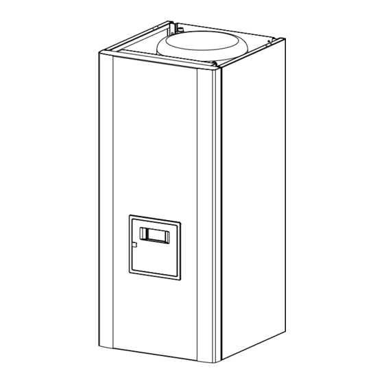
Page 11: Description
Heat pump, Split, single service Description Model 050, 065, 080 Model 128, 155 Model 095 Legend 1 - Low-noise, high-output coil 2 - Electric variable speed "inverter" motor 3 - "Inverter" control module 4 - Vacuum start (pump down) and control light 5 - Connection terminal blocks (power and interconnection) 6 - Refrigerant accumulator bottle... -
Page 12: Operating Principle
Heat pump, Split, single service Legend 1 - Electric box 2 - Regulator / User interface 3 - Start/stop switch 4 - Heating circulation pump 5 - Initial heating 6 - Gas refrigeration connection 7 - Fluid refrigeration connection 8 - Heating return 9 - Drain valve 10 - Safety valve 11 - Safety thermostat () - Page 13 Heat pump, Split, single service If no particular contract is concluded, the comfort Domestic hot water (DHW) operating principle temperature can be reached at any time, including Two domestic hot water (DHW) temperatures can be during the day parametered: comfort temperature (line 1610 to 60 The production of DHW takes priority over heating;...
-
Page 14: Installation
Heat pump, Split, single service 2 Installation Regulation installation and Accessories provided 2.2.3 maintenance conditions A c c e s s o r i e s p r o v i d e d w i t h t h e o u ts i d e u n i t The appliance must be installed and the maintained (figure 10). - Page 15 Heat pump, Split, single service • • The outside unit is able to withstand bad weather Nothing should obstruct the air circulation through but avoid installing in a position where it is likely to the evaporator and from the fan (fig. 12). be exposed to significant dirt or flowing water (under •...
-
Page 16: Outside Unit Positioning
Heat pump, Split, single service Heat pump Gas and fluid conduits M i n i m u m M a x i m u m M a x i l e v e l model Fluid length (L) length (L) difference (D) Module hydraulique... -
Page 17: Installing The Hydraulic Module
Heat pump, Split, single service Installing the hydraulic module The appliances are not fireproof and should not therefore be installed in a potentially explosive atmosphere. Installation precautions 2.5.1 Positioning the hydraulic module 2.5.2 • The room in which the appliance operates must comply with the prevailing regulations. -
Page 18: Rules And Precautions
Heat pump, Split, single service Refrigeration connections This appliance uses refrigerant R410A. Comply with the legislation for handling refrigeration Flaring tool fluids. Flare Rules and precautions 2.6.1 • After every intervention on the refrigeration circuit and before final connection, take care to replace the Hose plugs in order to avoid any pollution from the refrigeration circuit. -
Page 19: Shaping The Refrigeration Pipes
Heat pump, Split, single service Shaping the refrigeration pipes Connecting the flared connections 2.6.4 2.6.5 The refrigeration pipes must be shaped only on a The small pipe must always be connected bending machine or with a bending spring in order to before the large one. - Page 20 Heat pump, Split, single service - Depending on the case, connect an adapter (reducer) ¼’’- 3/8’’ or 1/2’’- 5/8’’. (see figure 19). - Remove the plugs from the pipes and the refrigeration connections. - Present the pipe to the flared connector and screw the nut by hand while holding the connector with a Coat the flared surface wrench until contact.
-
Page 21: Connections With Gas
Heat pump, Split, single service Filling the installation with gas Manometer kit (manifold) Vacuum meter This operation is reserved for installers High familiar with the legislation for handling pressure pressure refrigeration fluids. Creating a vacuum with a vacuum pump is essential. -
Page 22: Additional Charge
Heat pump, Split, single service Model 050 - Model 065 20 g of R410A per additional meter Length of the connections 10 m 15 m 20 m Additional charge none 100 g 200 g Model 080 20 g of R410A per additional meter Length of the connections 15 m 20 m... -
Page 23: Connecting
Heat pump, Split, single service Connecting Rinsing out the installation 2.8.2 the heating circuit hydraulically Before connecting the hydraulic module to the installation, rinse out the heating system correctly to General 2.8.1 e l i m i n a t e a n y pa r t i c l e s t h a t m a y a ff e c t t h e appliance’s correct operation. -
Page 24: Electrical Connections
Heat pump, Split, single service Electrical connections A : Rigid wires B : Flexible wires Round terminal tightened Loop Ensure that the general electrical power supply has 25 mm 10 mm been cut off before starting any repair work. Characteristic of the electrical supply 2.9.1 The electrical installation must be conducted in accordance with the prevailing regulations. -
Page 25: Overview Of All The Electrical Connections
Heat pump, Split, single service Overview of all the electrical connections 2.9.3 The wiring diagram for the hydraulic module is shown in detail on page 56. Outdoor sensor Cable 2 x 0.75 mm² Remote control (option) : cable 3 x 0.5 mm² Interconnection between the external unit and the hydraulic module Phase, Neutral, Earth, Communication bus... -
Page 26: Electrical Connections On Outside Unit Side
Heat pump, Split, single service Electrical connections on outside unit 2.9.5 side Access to the connection terminals • Model 050, 065, 080 - Remove the cap (figure 32). • Model 095, 128, 155 - Remove the front panel - Remove the cap (figure 34). Make the connections in accordance with the diagram(s) Fig. - Page 27 Heat pump, Split, single service Electrical connections on the hydraulic 2.9.6 module side Cable clamp Access to the connection terminals - Remove the front panel (2 screws) (fig. 16, p. 17) - Remove the cover of the electric box. - Make the connections in accordance with the diagram(s) Fig.
- Page 28 Heat pump, Split, single service Hydraulic module Outside unit Rp ECS Rp 1 Rp 2 1 2 3 4 5 6 7 8 9 10 11 121314151617 18 Electricity supply 230 V Resistance of the back-up unit 2 Resistance of the back-up unit 1 Interconnection between the outside unit and the hydraulic module HP and...
-
Page 29: Outdoor Sensor
Heat pump, Split, single service Outdoor sensor Room thermostat External fault circuit 1 Tariffs, day / night, peak times/off-peak times Power shedding or EJP (peak day removal) Room thermostat circuit 2 Remote control External component contact* (faults, load shedder, power meter) * If the control component does not provide a spare potential contact, the contact must be relayed to create equivalent wiring. -
Page 30: Start-Up
Heat pump, Split, single service • 2.13 Configuring the room thermostat Installation equipped with two room thermostats - Connect each of the sensors to one of the CL+ or CL- terminals on the heat pump control board Room thermostat (fig. 38, p. 29) using the connector supplied. To configure the room thermostat and connect it to the appropriate heating zone: •... -
Page 31: Regulation System
Heat pump, Split, single service 3 Regulation system User interface and remote control (Option) Figure 39 Ref. - Definitions Function - If the installation is fitted with a DHW tank. Selection of the DHW operating regime (Domestic hot water) - ON: Production of DHW according to the time program. - Off: Preparing the domestic hot water for stopping with the anti-frost function active. -
Page 32: Room Thermostat (Option)
Heat pump, Split, single service Room thermostat (Option) °C Figure 40 - Room thermostat (option) Ref. - Definitions Function Selecting the heating regime Heating operating according to the heating programme (Summer/winter mode switchover is automatic). Constant comfort temperature. Constant reduced temperature. Stand-by regime with anti-frost protection (Provided that the heat pump's electrical power supply is not interrupted). - Page 33 Heat pump, Split, single service Heating curve slope 1,25 Boiler connexion application temperature radiator 0,75 Heat pump application only Floor heating 0,25 system External temperature (°C) Figure 41 - Heating curve slope (line 720) Heating curve slope +4,5 -4,5 Curve off-set External temperature (°C) Figure 42 - Off-set of the heating curve (line 721) Sensations...
-
Page 34: User Interface And Remote Control Parametering The Setting
Heat pump, Split, single service Parametering the setting Setting parameters 3.6.2 - Choose the desired level. General 3.6.1 - Scroll the menu list. - Choose the desired menu. Only the parameters accessible to levels: - Scroll the function lines. U End user - Choose the desired line. - Page 35 Heat pump, Split, single service Line Function Setting range Setting Basic setting or display increment Operation HC2 Jointly with HC1 | Jointly with Independent This function enables you to choose whether you wish the room thermostat (as an option) to act on both zones or just a single zone.
- Page 36 Heat pump, Split, single service Line Function Setting range Setting Basic setting or display increment Standard values no, yes Time programme 5 / Cooling If the installation is fitted with the cooling kit (Only with the cooling kit option) Pre-selection (day / week) Mon-Sun Mon-Sun Mon-Fri Sat-Sun Monday Tuesday…...
- Page 37 Heat pump, Split, single service Line Function Setting range Setting Basic setting or display increment Limit of daily heating -10 °C … 10 °C 1 °C -3 °C This function enables you partially to offset the automatic summer/winter switchover during the intermediate seasons. Increasing the value delays the switchover to summer regime.
- Page 38 Heat pump, Split, single service Line Function Setting range Setting Basic setting or display increment Change of regime None, Protection mode, Protection Reduced, Comfort, mode Automatic Operating mode at end of concrete slab drying period Cooling circuit 1 Regime off, Automatic Comfort ambient temperature setpoint 17...40 °C 0,5 °C...
- Page 39 Heat pump, Split, single service Line Function Setting range Setting Basic setting or display increment 1014 U Frost-free ambient temperature setpoint from 4°C… to reduced 0,5 °C 8 °C temperature 1016 S Maximum comfort setpoint 20…35 °C 1 °C 28 °C 1020 I Heating curve slope 0.1...
- Page 40 Heat pump, Split, single service Line Function Setting range Setting Basic setting or display increment 1200 S Change of regime None, Protection mode, Protection Reduced, Comfort, mode Automatic Operating mode at end of concrete slab drying period DHW setting (domestic hot water) (Only with the DWH kit option) 1610 U Comfort setting 60 °C...
- Page 41 Heat pump, Split, single service Line Function Setting range Setting Basic setting or display increment 2920 S With electrical utility lock (EX4) Locked, Released Released Released : HP = ON _ Back-up DHW = off _ 1st back-up HP = off _ 2nd back-up HP = off _ Boiler = ON Locked : HP = off _ Back-up DHW = off _ 1st back-up HP = off _ 2nd back-up HP = off _ Boiler = ON Additional generator (Boiler connection) 3700 S...
- Page 42 Heat pump, Split, single service Line Function Setting range Setting Basic setting or display increment 6741 S Temperature alarm initiation CC2 ---, 10… 240 min 10 min 6745 S DHW load alarm ---, 1… 48 h 6746 S Temperature alarm initiation Cold 1 ---, 10…...
- Page 43 Heat pump, Split, single service Line Function Setting range Setting Basic setting or display increment Inputs / outputs test 7700 I Relay test No test This consists of instructing the regulator's relays one by one and checking their outputs. This enables you to check that the relays are working and that the cabling is correct.
- Page 44 Heat pump, Split, single service Line Function Setting range Setting Basic setting or display increment 8058 I History 5 Time, Date, State code 8060 I History 6 Time, Date, State code 8062 I History 7 Time, Date, State code 8064 I History 8 Time, Date, State code 8066 I...
- Page 45 Heat pump, Split, single service Line Function Setting range Setting Basic setting or display increment 8740 U Room temperature 1 0 … 50 °C 20 °C Ambient temperature setting 1 4 … 35 °C 8743 U Flow temperature 1 0 … 140 °C Flow temperature setpoint 1 0 …...
-
Page 46: Configuring The Installation
Heat pump, Split, single service 4 Configuring the installation Optional boiler connection kit The connection of an oil or gas boiler to the heat Optional DHW kit pump r equires the installation of the boiler DHW tank control (with electrical back-up) requires connection kit. -
Page 47: Configuration 1, 2, 3 Or 4: Electrical Connections
Heat pump, Split, single service Configuration 1, 2, 3 or 4: heat pumps with electric back-ups Parameter 5700 Configuration 1 : 1 heating circuit (See Figure page 48) Configuration 2 : 1 heating circuit and DHW tank. (See Figure page 49) Configuration 3 : 2 heating circuits (See Figure page 50) Configuration 4 : 2 heating circuits and DHW tank. - Page 48 Heat pump, Split, single service Configuration 1 : See detailed instructions 1 heating circuit. on Page 47 Overall hydraulic layout Overview of all the electrical connections Legend SA - Room thermostat (option) CC - Heating circulation pump SE - Outdoor sensor R - Radiators (or fan convectors) SP - Heated floor thermal safety fuse Installation and operating manual “1350-EN”...
- Page 49 Heat pump, Split, single service Configuration 2 : See detailed instructions 1 heating circuit and DHW tank. on Page 47 Overall hydraulic layout Overview of all the electrical connections Legend KS - DHW kit SP - Heated floor thermal safety fuse CAR - Non-return valve R - Radiators (or fan convectors)
- Page 50 Heat pump, Split, single service Configuration 3 : See detailed instructions 2 heating circuits on Page 47 Overall hydraulic layout Circuit 2 Circuit 1 SDp1 Overview of all the electrical connections Circuit 2 Circuit 1 SDp1 Legend SA1 - Room thermostat, Circuit 1 (option) CAR - Non-return valve SA2 - Room thermostat, Circuit 2 (option) CC1 - Heating circulation pump, Circuit 1 (Remote heat...
- Page 51 Heat pump, Split, single service Configuration 4 See detailed instructions 2 heating circuits and DHW tank. on Page 47 Overall hydraulic layout Circuit 2 Circuit 1 SDp1 Overview of all the electrical connections Circuit 2 Circuit 1 SDp1 Legend KS - DHW kit SE - Outdoor sensor AE - Electric back-up K2c - 2nd circuit kit...
-
Page 52: Electrical Wiring Diagrams
Heat pump, Split, single service 5 Electrical wiring diagrams Reactance Compressor R (R) White White White Evaporator Black S (S) Black outlet C (T) Black Black CN71 Brown Discharge Brown Black CN801 White Ventilator Yellow Brown Blue Compressor CN73 Brown Regulation board Evaporator Black... - Page 53 Heat pump, Split, single service CN90 HP pressure switch Regulation board Brown Compressor CN64 Brown CN400 CN42 CN40 CN200 Blue Outside CN62 Blue Black Evaporator centre CN61 Black Brown Discharge CN60 Brown Black 4-way valve CN303 CN301 CN500 W306 Black CN11 W307 White...
- Page 54 Heat pump, Split, single service Temperature sensors Outside Evaporator outlet Blue Black Compressor Discharge Brown Brown Compressor casing Evaporator centre Black Black Compressor HP pressure switch R(R) Black White White 4-way valve Fuse S(S) Black Black C(T) Black Brown Module Black Ventilator 1 Orange...
- Page 55 Heat pump, Split, single service Temperature sensors Compressor Connector Filter EMI HP pressure switch Black 4-way valve White White Black Fuse Black Black Black Ventilator 1 Brown White Active Yellow Regulation board Orange Brown filter unit Terminal block Yellow White Black Ventilator 2 White...
- Page 56 Heat pump, Split, single service CN106 Condensation CN103 sensor CN114 CN105 CN113 CN116 CN104 CN14 CN15 Timed fuse 3,15 A - 250V Return sensor Flow sensor Heating circulation pump Uref Connections to the heat pump r e g u l a t o r ( a c c e s s o r i e s a n d options) (see figure 38, page 29) Safety thermostat A1 A2...
-
Page 57: Troubleshooting
Heat pump, Split, single service 6 Troubleshooting Depending on whether the fault comes from the The display shows the “Bell” symbol outside unit or the hydraulic module, the fault may be indicated by the digital display or the diode on the Press the Info key for more details on the origin interface cards. -
Page 58: Faults Displayed On The Outside Unit
Faults displayed on the outside unit To access the electronic board, you must remove the front (right-hand) facing from the outside unit. Faults are coded by diode flashes. Outside unit, Reference AOYA18LALL (Model 050 and 065) and Reference AOYA24LALL (Model 080) Diode display Erroneous element... -
Page 59: Information Display
Heat pump, Split, single service Outside unit, Reference AOYA45LATL, AOYA45LBTL (Model 128) and Reference AOY54LJBYL (Model 155) Diode display Erroneous element 1 Flash Transmission error, "hydraulic module - outside unit" 2 Flashes Defective “discharge” temperature sensor 3 Flashes Defective “evaporator” temperature sensor 4 Flashes Defective “outside”... -
Page 60: Instructions For The User
Heat pump, Split, single service 7 Instructions for the user Explain to the user how his installation operates, in Emphasise that a heated floor has significant inertia particular the functions of the room thermostat and and that therefore any adjustments must be made the programmes accessible to him from the user progressively interface.
Need help?
Do you have a question about the AOYA18LALL and is the answer not in the manual?
Questions and answers
I need a photo of the nameplate of the exterior machine. All the numbers have been deleted and I can't write down the technical data of the machine. My machine is Fujitsu AOYA18LALL, and It is impossible to find such data from such an old machine