Table of Contents
Advertisement
Quick Links
Advertisement
Table of Contents

Related Manuals for AXIOMTEK UST510-52B-FL Series


Summary of Contents for AXIOMTEK UST510-52B-FL Series
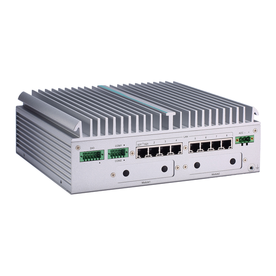
- Page 1 UST510-52B-FL Series Embedded System User’s Manual...
-
Page 2: Disclaimers
Disclaimers This manual has been carefully checked and believed to contain accurate information. Axiomtek Co., Ltd. assumes no responsibility for any infringements of patents or rights of any third party, or any liability arising from such uses. Axiomtek does not warrant or assume any legal liability or responsibility for the accuracy, completeness or usefulness of any information in this document. -
Page 3: Safety Precautions
Safety Precautions Before getting started, please read the following important safety precautions. The UST510-52B-FL does not come with an operating system which must be loaded first before installation of any software into the computer. Be sure to ground yourself to prevent static charge when installing any internal components. -
Page 4: Classifications
Classifications Degree of production against electric shock: not classified Degree of protection against ingress of water: IP40* Equipment not suitable for use in the presence of a flammable anesthetic mixture with air, oxygen or nitrous oxide. Mode of operation: Continuous... -
Page 5: General Cleaning Tips
General Cleaning Tips Please keep the following precautions in mind while understanding the details fully before and during any cleaning of the computer and any components within. A piece of dry cloth is ideal to clean the device. Be cautious of any tiny removable components when using a vacuum cleaner to absorb dirt on the floor. -
Page 6: Repair & Scrap Computer Recycling
Repair & Scrap Computer Recycling Please contact the nearest Axiomtek distributor as soon as possible for suitable solutions when computers require maintenance, repair or recycling. Trademarks Acknowledgments Axiomtek is a trademark of Axiomtek Co., Ltd. IBM, PC/AT, PS/2, VGA are trademarks of International Business Machines Corporation. -
Page 7: Table Of Contents
Table of Contents Disclaimers ......................i Safety Precautions ....................iii Classifications ....................... iv General Cleaning Tips ................... v Repair & Scrap Computer Recycling ..............vi SECTION 1 INTRODUCTION................. 1 General Descriptions ................. 1 System Specifications ............... 3 1.2.1 Driver Contents ....................5 Dimensions .................. - Page 8 3.3.3 Serial Port Connector (COM1~COM2) ............34 3.3.4 Ethernet & Power over Ethernet Connector ..........34 3.3.5 USB 3.0 Connector ..................36 3.3.6 Audio Connector .................... 36 3.3.7 Digital I/O ......................36 3.3.8 SATA Connector (SATA 1~4) ............... 36 3.3.9 SATA Power Connector ................
-
Page 9: Section 1 Introduction
UST510-52B-FL Series user’s Manual SECTION 1 INTRODUCTION This section contains general information and detailed specifications of the UST510-52B-FL. Section 1 consists of the following sub-sections: ◼ General Descriptions ◼ System Specifications ◼ Dimensions ◼ I/O Outlets ◼ Packing List ◼... - Page 10 UST510-52B-FL Series user’s Manual Features ® ® ® ⚫ LGA1151 socket 8 generation Intel Xeon & Core™ i7/i5/i3 & Celeron ® processor (Coffee Lake) with Intel C246 ⚫ ECC SO-DIMM memory supported, up to 64GB ⚫ Supporting wide range of DC power input from 9 to 36VDC ⚫...
-
Page 11: System Specifications
UST510-52B-FL Series user’s Manual 1.2 System Specifications ⚫ LGA1151 socket 8th / 9th generation Intel® Core ™ i7/i5/i3 & ◼ Xeon® /Pentium® /Celeron® processor, CPU TDP max. up to 35W/65W. ⚫ Chipset ◼ ® Intel C246 ⚫ BIOS ◼ American Megatrends Inc. UEFI (Unified Extensible Firmware Interface) BIOS. - Page 12 UST510-52B-FL Series user’s Manual ⚫ Storage RAID 0/1 supported via2 x 2.5” SATA HDD/SSD drive, up to 9.5mm in height ◼ ◼ RAID 0/1/5/10 supported via 4 x 2.5" SATA HDD/SSD, up to 9.5mm in height ◼ 2 x mSATA(occupied 2 x PCI Express Mini Card slot) ⚫...
-
Page 13: Driver Contents
240mm (9.45") (W) x 210.5mm (8.29”) (D) x 82.2mm (3.24") (H) ◼ 4 SATA (without wall mount) 240mm (9.44") (W) x 210.5mm (8.29") (D) x 104.2mm (4.1") (H) 1.2.1 Driver Contents Please download the drivers from the Axiomtek official website. ⚫ Ethernet ⚫ Chipset ⚫... -
Page 14: Dimensions
UST510-52B-FL Series user’s Manual 1.3 Dimensions The following diagrams show the dimensions and outlines of the UST510-52B-FL. 1.3.1 UST510-52B-FL Dimensions Model with 2 SATA Introduction... - Page 15 UST510-52B-FL Series user’s Manual Model with 4 SATA Introduction...
-
Page 16: I/O Outlets
UST510-52B-FL Series user’s Manual 1.4 I/O Outlets The following figures show I/O outlets on the UST510-52B-FL. Front View Introduction... - Page 17 UST510-52B-FL Series user’s Manual Rear View Introduction...
- Page 18 UST510-52B-FL Series user’s Manual Motherboard TOP View For more information about Connector, please refer to Chapter 3. Introduction...
- Page 19 UST510-52B-FL Series user’s Manual Motherboard Bottom View For more information about Connector, please refer to Chapter 3. Introduction...
-
Page 20: Packing List
M.2 key A & E 2230 size slot screw x 1 ⚫ M.2 Key B 3050/3052 size slot screw & holder x 1 Please contact an Axiomtek distributor immediately if any of the item above is missed. 1.6 Model List Fanless embedded system with 9th/8th gen Intel® desktop... -
Page 21: Section 2 Hardware Installation
UST510-52B-FL Series user’s Manual SECTION 2 HARDWARE INSTALLATION The UST510-52B-FL is user-friendly for various hardware configurations, such as CPU, DRAM, HDD (Hard Disk Drive), SSD (Solid State Drive), and PCI Express Mini card modules. Section 2 contains guidelines for hardware installation. - Page 22 UST510-52B-FL Series user’s Manual Step 3 CPU installation steps: ⚫ Take out the processor from package by holding the edges. ⚫ Double-check the processor package’s gold pads for any foreign material. ⚫ Locate connection 1 indicator on the processor which aligns with connection 1 indicator chamfer on the socket, and notice processor keying features that line up with posts along socket walls.
- Page 23 UST510-52B-FL Series user’s Manual Step 4 Take the protective cover down carefully. Step 5 Stick thermal pad and install DRAM and CPU . ※ When installing the CPU, pay attention to the CPU’s orientation and align the arrow mark on the CPU with the arrow key on the socket (Step 4). And apply the thermal pad on top of the processor.
- Page 24 UST510-52B-FL Series user’s Manual Step Put the top cover back onto the system and fasten all screws. Note: When removing the top cover to change components, the CPU will stick on the underside of the cover. To avoid damaging the CPU by squeezing, please take it down carefully by holding the edges of the CPU and follow section 2.1 to reinstall.
- Page 25 UST510-52B-FL Series user’s Manual Put the thermal pads on the heatsink according to the marked lines. Note: It is suggested that the thermal pads be put on the motherboard’s corresponding positions as shown. Hardware Installation...
-
Page 26: Installing 2.5" Sata Device
UST510-52B-FL Series user’s Manual 2.2 Installing 2.5” SATA Device 2.2.1 Installing 2.5” SATA Device Step 1 Turn off the system and unplug the power cord. Step 2 Loosen all of the SATA drive tray’s screws and extract the SATA drive tray. - Page 27 UST510-52B-FL Series user’s Manual Step 4 Slide the secured SATA drive tray back into the system and fasten the screws firmly to complete the installation. Hardware Installation...
-
Page 28: Installing Mini Pcie / M.2 Module
UST510-52B-FL Series user’s Manual 2.3 Installing Mini PCIe / M.2 Module 2.3.1 Installing Mini PCIe / M.2 Module Step 1 Turn off the system and unplug the power cord. Step 2 Turn the system upside down and loosen the SATA trays. - Page 29 UST510-52B-FL Series user’s Manual Step 5 Insert the PCIe card and fasten the screws as shown . Step 6 Insert the M.2 2230 E key card and fasten the screw as shown. Step 7 Insert the M.2 3050/3052 B key card and fasten the screws as shown.
-
Page 30: Installing The Wall Mount Kit
UST510-52B-FL Series user’s Manual 2.4 Installing the Wall Mount Kit 2.4.1 Installing the Wall Mount Kit Step 1 Turn off the system and unplug the power cord. Step 2 Locate the wall mount screw holes on both sides of the system. -
Page 31: Installing Ax92912 Kit & Ax92918 Kit
UST510-52B-FL Series user’s Manual 2.5 Installing AX92912 kit & AX92918 kit 2.5.1 Installing AX92912 Full-size Gigabit Ethernet Mini PCI- Express Module kit ⚫ Packing List AX92912 Board x1 M2 Screw x2 Quick Installation Guide x 1 M3 Countersunk Flat Head Screw x2... - Page 32 UST510-52B-FL Series user’s Manual Step 4 Remove the SATA tray, loosen all the screws on the bottom cover, and open the bottom cover. ※ After lifting up the cover, please remove the fixed SATA cable first and then put the cover aside.
- Page 33 UST510-52B-FL Series user’s Manual Step 6 Connect the cables to the module and secure it to the motherboard using M2 screws. Step 7 Attach the thermal pad to the corresponding IC positions on the module and secure the heatsink using M3 button head screws.
- Page 34 UST510-52B-FL Series user’s Manual Step 8 Organize the cables and reinstall them into the SATA trays according to Step 5, then tighten all the screws. [Note] For manufacturing the external cables, you can refer to the pin definitions below. It is recommended to use shielding for manufacturing the wires.
-
Page 35: Installing Ax92918 Full-Size Gigabit Ethernet Mini Pci-Express Module Kit
UST510-52B-FL Series user’s Manual 2.5.2 Installing AX92918 Full-size Gigabit Ethernet Mini PCI- Express Module kit ⚫ Packing List AX92918 Board x1 M2 Screw x2 Quick Installation Guide x 1 M3 Countersunk Flat Head Screw x4 AX93287 Board x2 M3 Flat Head Screw x 4... - Page 36 UST510-52B-FL Series user’s Manual Step 5 Take out the SATA tray of UST510 and remove the bottom cover. ※ After lifting up the cover, please remove the fixed SATA cable first and then put the cover aside. Hardware Installation...
- Page 37 UST510-52B-FL Series user’s Manual Step 6 Remove the original antenna bracket and attach the RJ45 bracket to the panel. Step 7 Apply the thermal pad to the corresponding IC positions on the LAN module, and then use M2 screws to install the LAN module AX92918 onto the motherboard.
- Page 38 UST510-52B-FL Series user’s Manual Step 8 Connect the module to the cable and organize the wires. Step 9 Fasten the heatsink by using M3 button head screws. Step 10 Re-install the SATA trays according to step 5 and fasten all the screws.
-
Page 39: Section 3 Led, Button & Connector Settings
UST510-52B-FL Series user’s Manual SECTION 3 LED, BUTTON & CONNECTOR SETTINGS 3.1 LED Functions Descriptions Power LED (note1) OS Storage LED Programmable LED(note2) Programmable LED(note2) With Smart Ignition, users can realize the malfunction status by the Note 1: blink of PWR LED. Please refer to the table. For more detailed setting, please refer to BIOS Chapter4.4 smart ignition configuration. -
Page 40: Buttons
UST510-52B-FL Series user’s Manual 3.2 Buttons 3.2.1 Power Button (SW1) The power button is located on the I/O side. It allows users to control power on/off state of the UST510-52B-FL. Refer to APPENDIX C for instructions on power button settings for Windows. -
Page 41: Connectors
UST510-52B-FL Series user’s Manual 3.3 Connectors Please refer to pin assignments below: 3.3.1 DC-in Power Connector (CN34) ⚫ Wide-range 9 - 36VDC (typical 24VDC) power input with terminal block. ⚫ OVP and RVP protection. ⚫ Supports Axiomtek Smart Ignition. Pins... -
Page 42: Serial Port Connector (Com1~Com2)
UST510-52B-FL Series user’s Manual 3.3.3 Serial Port Connector (COM1~COM2) ⚫ 1 port TB supports 2COM ⚫ COM mode supports RS-232/422/485 (which can be selected by BIOS) ⚫ Pin assignment is listed as follows: RS232 RS422 RS485 RS232 RS422 RS485 3.3.4 Ethernet &... - Page 43 UST510-52B-FL Series user’s Manual LAN1 to LAN8 (RJ45 type with PoE)are based on the Intel i211 with PoE support on the rear side panel. Pins LAN Signal Pins LAN Signal MDI0+ (Passive V MDI2+ (Passive V MDI0- (Passive V MDI2- (Negative V...
-
Page 44: Usb 3.0 Connector
UST510-52B-FL Series user’s Manual 3.3.5 USB 3.0 Connector The Universal Serial Bus connectors are compliant with USB 3.0 (5 GB/s), ideal for connecting USB peripherals such as scanners, cameras and other USB devices. Pin assignment follows USB Implementers Forum, Inc. -
Page 45: Sata Power Connector
Signals +5V level 3.3.10 Remote Switch Connector (CN9) With the Flexible IO kit installed, a remote switch can be added to the position of the flexible IO window.( Please contact AXIOMTEK for inquiries.) Pins Signals Description Low Active. Acts as PC’s power button when an external switch is installed (Pin1 active). -
Page 46: Pci Express Mini Card Slot
UST510-52B-FL Series user’s Manual 3.3.12 PCI Express Mini Card Slot Full-Size (CN15) The UST510-52B-FL supports full-size PCI-Express Mini Card slots. CN15 supports PCI- Express or SATA (mSATA) via BIOS selection and USB signals; PCI-Express complies with PCI-Express Mini Card Spec. V1.2. Thus, users can install a mSATA or WLAN/WWAN card into this slot. - Page 47 UST510-52B-FL Series user’s Manual Half-Size (CN17) CN17 supports USB2.0 and SATA (mSATA) signals and complies with PCI-Express Mini Card Spec. V1.2. Thus, users can install a mSATA card into this slot. Pins Signals Pins Signals +3.3Vaux +1.5V +3.3Vaux +3.3Vaux USB_D+...
-
Page 48: Key E Connector (Cn18)
UST510-52B-FL Series user’s Manual 3.3.13 M.2 Key E Connector (CN18) The system comes with one M.2 Key E connector (Wi-Fi & Bluetooth) Pins Signals Pins Signals +3.3V +3.3V USB#14_D+ USB#14_D- PCM_CRF_RST[*] CNV_WR_1_DN[*] CNV_WR_1_DP[*] PCMOUT_CLKREQ0[*] CNV_WR_0_DN[*] CNV_WR_0_DP[*] UART_BT_WAKE[*] CNV_BRI_RSP[*] CNV_WR_CLK_DN[*] CNV_WR_CLK_DP[*]... -
Page 49: 3050/3052 Key B (Cn14)
UST510-52B-FL Series user’s Manual 3.3.14 M.2 3050/3052 Key B (CN14) The system comes with one M.2 Key B connector (LTE & SIM). Signal Signal Signal Signal CONFIG_3 +3.3V +3.3V Full Card PWR OFF USB_D+ W_DISABLE1# USB_D- GPIO_9 Key B Key B... - Page 50 UST510-52B-FL Series user’s Manual This page is intentionally left blank. LED, Button & Connector Settings...
-
Page 51: Section 4 Bios Setup Utility
UST510-52B-FL Series user’s Manual SECTION 4 BIOS SETUP UTILITY This section provides users with detailed description s in terms of how to set up basic system configurations through the BIOS setup utility. 4.1 Starting To enter the setup screens, follow the steps below: Turn on the computer and press the <Del>... -
Page 52: Navigation Keys
UST510-52B-FL Series user’s Manual 4.2 Navigation Keys The BIOS setup/utility uses a key-based navigation system called hot keys. Most of the BIOS setup utility hot keys can be used at any time during the setup navigation process. These keys include <F1>, <F2>, <Enter>, <ESC>, <Arrow> keys, and so on. -
Page 53: Main Menu
UST510-52B-FL Series user’s Manual 4.3 Main Menu The Main Menu screen is the first screen users see when entering the setup utility. Users can always return to the Main setup screen by selecting the Main tab. System Time/Date can be set up as described below. -
Page 54: Advanced Menu
UST510-52B-FL Series user’s Manual 4.4 Advanced Menu The Advanced menu also allows users to set configuration of the CPU and other system devices. Users can select any items in the left frame of the screen to go to sub menus: MiniCard Switch ►... - Page 55 UST510-52B-FL Series user’s Manual Mini Card switch Use this to select Mini Card setting, default is “PCIE”. BIOS Setup Utility...
- Page 56 UST510-52B-FL Series user’s Manual CPU Configuration This screen shows the CPU version and its detailed information. Intel Virtualization Technology It allows a hardware platform to run multiple operating systems separately and simultaneously, enabling one system to virtually function as several systems.
- Page 57 UST510-52B-FL Series user’s Manual NCT6106D Super IO Configuration In this screen user can select options for the NCT6106D Super IO Configurations, and change the value of the selected option. A description of the selected item appears on the right side of the screen. For items marked with “ ”, press <Enter> for more options The default setting for all Serial Ports is RS232.
- Page 58 UST510-52B-FL Series user’s Manual Serial Port 1 & 2 Configuration BIOS Setup Utility...
- Page 59 UST510-52B-FL Series user’s Manual Select Mode Use this option to set RS-232/RS-422/RS-485 mode. BIOS Setup Utility...
- Page 60 UST510-52B-FL Series user’s Manual NCT6106D Hardware Monitor This screen displays the temperatures of system and CPU and system voltages (VCORE, +3.3V, +12V and +5V). BIOS Setup Utility...
- Page 61 UST510-52B-FL Series user’s Manual SATA & RST Configuration SATA Mode Selection AHCI (Advanced Host Controller Interface) mode is how SATA controller(s) operate. Serial ATA Port 0~5 It shows the device installed in connector SATA0~5. BIOS Setup Utility...
- Page 62 UST510-52B-FL Series user’s Manual Trusted Computing This screen provides function for specifying the TPM settings. Security Device Support Enable or disable BIOS support for security device. OS will not show security device. TCG EFI protocol and INT1A interface will not be available.
- Page 63 UST510-52B-FL Series user’s Manual Enable or Disable Endorsement Hierarchy. Physical Presence Spec Version Select to Tell O.S. to support PPI Spec Version 1.2 or 1.3. Some HCK tests might not support 1.3. Note: Device Select TPM 1.2 will limit the support to TPM 1.2 devices, TPM 2.0 will limit the support to TPM 2.0devices.
- Page 64 UST510-52B-FL Series user’s Manual USB Configuration This screen specifies USB settings. USB Devices Display all detected USB devices. BIOS Setup Utility...
- Page 65 UST510-52B-FL Series user’s Manual Device Configuration The DIO Modification default setting is “disable”. If the setting is changed to “enable”, you can load manufacture default and program DIO setting. (Please refer to below graphics.) BIOS Setup Utility...
- Page 66 UST510-52B-FL Series user’s Manual BIOS Setup Utility...
- Page 67 UST510-52B-FL Series user’s Manual BIOS Setup Utility...
- Page 68 UST510-52B-FL Series user’s Manual Smart Ignition Configuration The Smart Ignition Management setting includes Axiomtek’s latest technology in ignition management. Please read the description below with pictures. Note:If the user needs to use more in-depth function, please refer to the Smart Ignition technical document.
- Page 69 UST510-52B-FL Series user’s Manual Auto Power On Enabled System will turn on automatically under below conditions - Manually disconnects and reconnects system power - Power interruption: Resumes power after power fail Disabled System will not turn on automatically when power is...
- Page 70 UST510-52B-FL Series user’s Manual BIOS menu item Description Activate Voltage Trigger The system only turns on when the voltage delivered by the power source is higher than the value you set here. Low Voltage Trigger The system will begin countdown stage once voltage drops below the value you set here.
- Page 71 UST510-52B-FL Series user’s Manual Version It displays PoE Controller FW version. Power Budget Itdisplays current total power budget on all ports. Please be advised that, when setting up power budget, the power budget must Note: be not lower than thetotal of Power Device (PD) operating watts and Power Classifications Watts.
- Page 72 UST510-52B-FL Series user’s Manual Restore the default settings and save to POE. Default: Power Budget 90w, all ports enabled. Port1~Port16 Enable/Disable a specific POE port and display all port status. BIOS Setup Utility...
-
Page 73: Chipset Menu
UST510-52B-FL Series user’s Manual 4.5 Chipset Menu The Chipset menu allows users to change the advanced chipset settings. Users can select any of the items in the left frame of the screen to go to the sub menus: ► System Agent (SA) Configurations ►... - Page 74 UST510-52B-FL Series user’s Manual System Agent (SA) Configurations BIOS Setup Utility...
- Page 75 UST510-52B-FL Series user’s Manual Memory Configuration Use this item to refer to the information related to system memory. This screen shows the system memory information. BIOS Setup Utility...
- Page 76 UST510-52B-FL Series user’s Manual PCH-IO Configuration This screen shows ME Firmware information. BIOS Setup Utility...
-
Page 77: Security
UST510-52B-FL Series user’s Manual 4.6 Security Administrator Password This item indicates whether an administrator password has been set (installed or uninstalled). User Password This item indicates whether a user password has been set (installed or uninstalled). Secure Boot ® This item allows you to configure the Windows Secure Boot settings and manage its keys to protect the system from unauthorized access and malwares during POST. - Page 78 UST510-52B-FL Series user’s Manual Secure Boot This item can Enable or Disable Secure Boot Mode. Secure Boot Mode Use this item to set UEFI Secure Boot Mode to Standard mode or Custom mode. This change is effective after save. After reset, this mode will return to Standard mode.
-
Page 79: Boot Menu
UST510-52B-FL Series user’s Manual 4.7 Boot Menu The Boot menu allows users to change boot options of the system, providing UEFI, Legacy, and Compatible modes to select from. The default setting boot mode is [UEFI Mode]. (Please refer to below graphics.) - Page 80 UST510-52B-FL Series user’s Manual Setup Prompt Timeout Use this item to set up number of seconds to wait for setup activation key where 65535(0xFFFF) means indefinite waiting. Bootup NumLock State Use this item to select the power-on state for the keyboard NumLock.
-
Page 81: Save & Exit Menu
UST510-52B-FL Series user’s Manual 4.8 Save & Exit Menu The Save & Exit menu allows users to determine whether or not to accept their modifications to the system configuration, or to keep default values for optimal fail-safe performance. (Please refer to below graphics.) - Page 82 UST510-52B-FL Series user’s Manual BIOS menu Description item Save Changes When users have completed the system configuration changes, select and Exit this option to leave Setup and return to Main Menu. Select Save Changes and Exit from the Save & Exit menu and press <Enter>. Select Yes to save changes and exit.
-
Page 83: Appendix Awatchdog Timer
How to Use the Watchdog Timer The user can configure the watchdog timer using the watchdog function included in the AXVIEW2.0 software developed by Axiomtek or using the debug.exe software released by Microsoft. NOTE: The related tool for setting WDT will not be available on the official download page. If you need any tool, please contact Axiomtek’s local distributor immediately. - Page 84 UST510-52B-FL Series user’s Manual Disable watchdog timer STEP Sample code Note 1. Enter configuration mode O 2E 87 Un-lock super I/O O 2E 87 Un-lock super I/O 2. Select logic device O 2E 07 Select logic register O 2F 08 Switch to WDT device 3.
-
Page 85: Appendix Bdigital I/O
UST510-52B-FL Series user’s Manual APPENDIX B DIGITAL I/O Digital I/O Specification Digital Input: Input channels: 6, source type Input voltage: 0 to 30VDC Input level for dry contacts: Logic level 0: close to ground Logic level 1: open Input level for wet contacts: Logic level 1: +3VDC max. - Page 86 UST510-52B-FL Series user’s Manual Digital Output Wiring Digital I/O...
-
Page 87: Appendix C Power Button Setting For Windows
UST510-52B-FL Series user’s Manual APPENDIX C POWER BUTTON SETTING FOR WINDOWS To enable the power button function, go to the console of the PC and then follow below figures to complete the setting. Power Button Setting For Windows... - Page 88 UST510-52B-FL Series user’s Manual Please check if the action of pressing the power button is “Shut down” to let ACC work normally and prevent unexpected hard shut down. Power Button Setting For Windows...
-
Page 89: Appendix D Programmable Led
UST510-52B-FL Series user’s Manual APPENDIX D Programmable LED please contact FAE for further information. If the user needs to use this function, Programmable LED...
Need help?
Do you have a question about the UST510-52B-FL Series and is the answer not in the manual?
Questions and answers