Table of Contents
Advertisement
Quick Links
Advertisement
Table of Contents

Related Manuals for AXIOMTEK EBOX670-891-FL Series


Summary of Contents for AXIOMTEK EBOX670-891-FL Series
- Page 1 Series Embedded System User’s Manual...
-
Page 2: Disclaimers
Axiomtek does not make any commitment to update any information in this manual. Axiomtek reserves the right to change or revise this document and/or product at any time without notice. No part of this document may be reproduced, stored in a retrieval system, or transmitted in any forms or by any means, electronic, mechanical, photocopying, recording, among others, without prior written permissions of Axiomtek Co., Ltd. -
Page 3: Safety Precautions
Safety Precautions Before getting started, please read the following important safety precautions. The eBOX670-891-FL does not come with an operating system which must be loaded first before installation of any software into the computer. Be sure to ground yourself to prevent static charge when installing any internal components. -
Page 4: Classifications
Classifications Degree of production against electric shock: not classified Degree of protection against ingress of water: IP40 Equipment not suitable for use in the presence of a flammable anesthetic mixture with air, oxygen or nitrous oxide. Mode of operation: Continuous... -
Page 5: General Cleaning Tips
General Cleaning Tips Please keep the following precautions in mind while understanding the details fully before and during any cleaning of the computer and any components within. A piece of dry cloth is ideal to clean the device. Be cautious of any tiny removable components when using a vacuum cleaner to absorb dirt on the floor. -
Page 6: Scrap Computer Recycling
Scrap Computer Recycling Please inform the nearest Axiomtek distributor as soon as possible for suitable solutions in case computers require maintenance or repair; or for recycling in case computers are out of order. Trademarks Acknowledgments Axiomtek is a trademark of Axiomtek Co., Ltd. -
Page 7: Table Of Contents
Table of Contents Disclaimers ....................... ii Safety Precautions ....................iii Classifications ......................iv General Cleaning Tips ..................... v Scrap Computer Recycling ..................vi SECTION 1 INTRODUCTION ..................1 General Descriptions ................1 System Specifications ................. 2 1.2.1 CPU ........................2 1.2.2 I/O System ...................... - Page 8 3.3.13 AT/ATX Switch ....................30 3.3.14 CFast™ Socket ....................31 3.3.15 SATA Connector (SATA 1 & 2) ................ 32 3.3.16 SATA Power Connector ................... 32 3.3.17 SIM Card Slots (SCN1) ..................32 3.3.18 Full-Size PCI Express Mini Card Slot (SCN2 & SCN3) ........33 SECTION 4 BIOS SETUP UTILITY ................
-
Page 9: Section 1 Introduction
Series user’s Manual SECTION 1 INTRODUCTION This section contains general information and detailed specifications of the eBOX670-891-FL.Section 1 consist of the following sub-sections: General Descriptions System Specifications Dimensions I/O Outlets Packing List Model List 1.1 General Descriptions... -
Page 10: System Specifications
Series user’s Manual Features ® ® Core™ i7/i5/i3 & Celeron LGA1151 socket 6th generation Intel processor ® (Skylake) with Intel Q170 Supports Jumbo Frame (9.5k), W oL, PXE Remote Boot, Teaming W ide range of DC power input supported from 9 to 36VDC ... -
Page 11: I/O System
Series user’s Manual 1.2.2 I/O System Display 2 x HDMI (1 x HDMI 2.0 Resolution:4K/2K@60Hz & 1 x HDMI 1.4b Resolution : 4K/2K@30Hz) 1 x DisplayPort (Resolution:4K/2K@60Hz) Ethernet 4 x 10/100/1000 Ethernet ports (3 x i210IT & 1 x i219LM) ... -
Page 12: System Specifications
Series user’s Manual 1.2.3 System Specifications Watchdog Timer 1~255 seconds or minutes; up to 255 levels. Power Supply 9~36VDC input Operation Temperature -30℃ ~+60℃ (-22 ºF ~ 131ºF), with W .T. SSD & Memory) ... -
Page 13: Dimensions
Series user’s Manual 1.3 Dimensions The following diagrams show dimensions and outlines of the eBOX670-891-FL. 1.3.1 System Dimensions Introduction... -
Page 14: Wall-Mount Bracket Dimensions
Series user’s Manual 1.3.2 Wall-mount Bracket Dimensions Introduction... -
Page 15: I/O Outlets
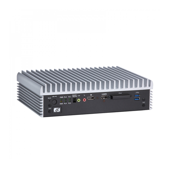
Series user’s Manual 1.4 I/O Outlets The following figures show I/O outlets on the eBOX670-891-FL. Front View Rear View Introduction... -
Page 16: Packing List
Core™ i7/i5/i3 & Celeron generation Intel processors, Intel eBOX670-891-FL-DC Q170 chipset, 2 HDMI, 1 DisplayPort, 4 GbE LANs, 6 USB 3.0, CFast™, dual PCI Express Mini Card slots Please contact Axiomtek’s distributors immediately in case any abovementioned items are missing. Introduction... -
Page 17: Section 2 Hardware Installation
Series user’s Manual SECTION 2 HARDWARE INSTALLATION The eBOX670-891-FL is convenient for various hardware configurations, such as CPU, DRAM, HDD (Hard Disk Drive), SSD (Solid State Drive), CFast card and PCI Express Mini card modules. Section 2 contains guidelines for hardware installation. - Page 18 Series user’s Manual Step 4 CPU installation steps: Lift processor package from shipping media by grasping the substrate edges. Scan the processor package gold pads for any presence of foreign material. Locate connection 1 indicator on the processor which aligns with connection 1 indicator chamfer on the socket, and notice processor keying features that line up with posts along socket walls.
- Page 19 Series user’s Manual Step 5 Align pins of the CPU with pin holes of the socket. Be careful of the CPU’s orientation that user’s need to align the arrow mark on the CPU with the arrow key on the socket.
-
Page 20: Installation Of 2.5" Sata Device
Series user’s Manual 2.2 Installation of 2.5" SATA Device Step 1 Turn off the system and unplug the power cord. Step 2 Turn the system upside down to locate screws at the bottom and then loosen all screws. Step 3 Open the bottom cover. - Page 21 Series user’s Manual Step 5 Before assemble the SSD/HDD, please loosen the thumb screws to remove two HDD brackets, and then assemble the SSD/HDD with the two HDD mounting screws. Make sure the PCB side of the SSD/HDD will be facing the bottom cover.
-
Page 22: Installation Of So-Dimm
Series user’s Manual 2.3 Installation of SO-DIMM Step 1 Turn off the system and unplug the power cord. Step 2 Four screws on the top heatsink are used to fasten the heatsink to the chassis. Step 3 Located the dual SO-DIMM sockets on main board. - Page 23 Series user’s Manual Step 4 Locate the memory module, insert a gold colored contact into the socket and push the module two end latches till locked. Step 5 Put the top cover and fasten four screws back onto the system.
-
Page 24: Installation Of Cfast
Series user’s Manual 2.4 Installation of CFast Module Step 1 Turn off the system and unplug the power cord. Step 2 Located the CFast slot on front panel. Step 3 Insert a CFast module into the socket. Step 4 Recover and fasten all screws of the top cover. -
Page 25: Installation Of Mini Pcie Module (Full-Size)
Series user’s Manual 2.5 Installation of Mini PCIe Module (full-size) Step 1 Turn off the system and unplug the power cord. Step 2 Turn the system upside down to locate screws at the bottom, and then loosen all screws. -
Page 26: Installation Of Flexible I/O Modules
Series user’s Manual 2.6 Installation of Flexible I/O Modules The eBOX670-891 provides an optional window for customer add flexible I/O modules, according to different modules , please refer to quick manual -LAN Module (RJ45*1) -DIO Module (DB9*1) -CAN Bus/CAN Open Module (DB9*2) - Page 27 Series user’s Manual Step 5 Assemble LAN connector with bracket. Step 6 Connected the cable with the LAN module. Step 7 Fasten the LAN bracket into the chassis, and then connect the LAN cable to the mini PCIe module.
- Page 28 Series user’s Manual This page is intentionally left blank. Hardware Installation...
-
Page 29: Section 3 Jumper & Connector Settings
Series user’s Manual SECTION 3 JUMPER & CONNECTOR SETTINGS Proper jumper settings configure the eBOX670-891-FL to meet various application needs. Hereby all jumpers settings along with their default settings are listed for devices onboard. 3.1 Locations of Jumpers & Connectors SBC87891 Top View Jumper &... - Page 30 Series user’s Manual SBC87891 Bottom View 【Note】: It is strongly recommended that any unmentioned jumper settings should not be modified without instructions by Axiomtek FAEs. Any modifications without instructions might cause system failure. Jumper & Connector Settings...
-
Page 31: Summary Of Jumper Settings
Series user’s Manual 3.2 Summary of Jumper Settings Proper jumper settings configure the eBOX670-891-FL to meet various application purposes. A table of all jumpers and their default settings is listed below. Jumpers Descriptions Settings Restore BIOS Optimal Defaults Short 1-2 Default: Normal Operation 【Note】: How to setup Jumpers... -
Page 32: Connectors
Series user’s Manual 3.3 Connectors Please refer to pin assignments below: External Connectors Sections DC-in Phoenix Power Connector 3.3.1 HDMI Connector 3.3.2 DisplayPort Connector 3.3.3 Serial Port Connector 3.3.4 USB 3.0 Connector 3.3.5 Ethernet Connector 3.3.6 USB 2.0 Connector 3.3.7... -
Page 33: Dc-In Phoenix Power Connector
Series user’s Manual 3.3.1 DC-in Phoenix Power Connector The system supports 9~36V Phoenix DC-in connector for system power input. Pins Signals 3.3.2 HDMI Connector The HDMI (High-Definition Multimedia Interface) is a compact digital interface which is capable of transmitting high-definition video and high-resolution audio over a single cable. -
Page 34: Displayport Connector
Series user’s Manual 3.3.3 DisplayPort Connector Pins Signals Pins Signals DPB_LANE0 DPB_LANE3# DPB_LANE0# Detect Pin DPB_LANE1 DPB_AUX DPB_LANE1# DPB_LANE2 DPB_AUX# DPB_HPDE DPB_LANE2# DPB_LANE3 +3.3V 3.3.4 Serial Port Connector (COM 1~COM 4) The system has four serial ports. COM1~COM4 are RS-232/422/485 ports. Please refer to Chapter 4 for the detail of BIOS setting. -
Page 35: Usb 3.0 Connector
Series user’s Manual 3.3.5 USB 3.0 Connector The Universal Serial Bus connectors are compliant with USB 3.0 (5 GB/s), and ideally for installing USB peripherals such as scanner, camera and USB devices, etc. Pins Signal USB Port 0 Pins... -
Page 36: Usb 2.0 Connector
Series user’s Manual 3.3.7 USB 2.0 Connector The Universal Serial Bus connectors are compliant with USB 2.0 (480Mbps), and ideally for installing USB peripherals such as keyboard, mouse, scanner, etc. Pins Signal USB Port USB VCC (+5V level) USB #0_D-... -
Page 37: Digital I/O
Series user’s Manual 3.3.9 Digital I/O The system is equipped with 32bit Programmable Digital I/O for 44-pin D-Sub female connectors, please refer to the following table to get default pin define. Default is 16in/16out. The digital I/O can be configured to control cash drawers and sense warning signals from an Uninterrupted Power System (UPS), or perform store security control. -
Page 38: Atx Power On/Off
Series user’s Manual 3.3.10 ATX Power On/OFF The ATX power button is on the I/O side. It can allow users to control eBOX670-891-FL power on/off. Functions Descriptions Turn on/off system Keep system status 3.3.11 Reset Button The Reset button can allow users to reset eBOX670-891-FL. -
Page 39: Cfast™ Socket
Series user’s Manual 3.3.14 CFast™ Socket The system is equipped with a CFast™ socket on the bottom side to support a CFast™ card which is based on the Serial ATA bus. The socket is specially designed to avoid incorrect installation of the CFast™... -
Page 40: Sata Connector (Sata 1 & 2)
Series user’s Manual 3.3.15 SATA Connector (SATA 1 & 2) These Serial Advanced Technology Attachment (Serial ATA or SATA) connectors are for high-speed SATA interfaces. They are computer bus interfaces for connecting to devices such as hard disk drives. This board has two SATA 3.0 ports with 6Gb/s performance. -
Page 41: Full-Size Pci Express Mini Card Slot (Scn2 & Scn3)
Series user’s Manual 3.3.18 Full-Size PCI Express Mini Card Slot (SCN2 & SCN3) The eBOX670-891-FL supports dual full-size PCI-Express Mini Card slots.SCN2 is applying to either PCI-Express or USB 2.0 signal, and complies with PCI-Express Mini Card Spec. V1.2. - Page 42 Series user’s Manual SCN3 Pins Signals Signals W AKE# +3.3VSB No use No use +1.5V CLKREQ# No use No use REFCLK- No use REFCLK+ No use No use No use No use W _DISABLE# PERST# PE_RXN3/mSATA +3.3VSB SATA_RXP PE_RXP3/mSATA SATA_RXN +1.5V...
-
Page 43: Section 4 Bios Setup Utility
Series user’s Manual SECTION 4 BIOS SETUP UTILITY This section provides users with detailed descriptions in terms of how to set up basic system configurations through the BIOS setup utility. 4.1 Starting To enter the setup screens, follow the steps below: Turn on the computer and press the <Del>... -
Page 44: Main Menu
Series user’s Manual 4.3 Main Menu The Main Menu screen is the first screen users see when entering the setup utility. Users can always return to the Main setup screen by selecting the Main tab. System Time/Date can be set up as described below. -
Page 45: Advanced Menu
Series user’s Manual 4.4 Advanced Menu The Advanced menu also allows users to set configuration of the CPU and other system devices. Users can select any items in the left frame of the screen to go to sub menus: ►... - Page 46 Series user’s Manual Mini Card Switch Use this to select Mini Card setting, default is “PCIE”. BIOS Setup Utility...
- Page 47 Series user’s Manual ACPI Settings Use this screen to select options for the ACPI configuration, and change the value of the selected option. A description of the selected item appears on the right side of the screen. ACPI Sleep State When the sleep button is pressed, the system will be in the ACPI sleep state.
- Page 48 Series user’s Manual CPU Configurations This screen shows the CPU version and its detailed information. Intel Virtualization Technology It allows a hardware platform to run multiple operating systems separately and simultaneously, enabling one system to virtually function as several systems.
- Page 49 Series user’s Manual SATA Configurations In this Configuration menu, you can see the currently installed hardware in the SATA ports. During system boot up, the BIOS automatically detects the presence of SATA devices. BIOS Setup Utility...
- Page 50 Series user’s Manual SATA Mode Selection AHCI (Advanced Host Controller Interface) mode is how SATA controller(s) operate. Serial ATA Port 0~3 It shows the device installed in connector SATA0~3 BIOS Setup Utility...
- Page 51 Series user’s Manual PCH-FW Configuration This screen shows ME Firmware information. BIOS Setup Utility...
- Page 52 Series user’s Manual AMT Configurations User can use this screen to configure AMT parameters. Intel AMT Enable or disable Intel Active Management Technology BIOS Extension. ® The default is enabled. BIOS Setup Utility...
- Page 53 Series user’s Manual USB Configurations USB Devices Display all detected USB devices. BIOS Setup Utility...
- Page 54 Series user’s Manual NCT6102D Super IO Configurations Use this screen to select options for the NCT6102D Super IO Configurations, and change the value of the selected option. A description of the selected item appears on the right side of the screen.
- Page 55 Series user’s Manual Serial Port 1 Select Mode Use this option to set RS-232/RS-422/RS-485 mode. Serial Port 2 BIOS Setup Utility...
- Page 56 Series user’s Manual NCT6102DSEC Super IO Configurations Use this screen to select options for the NCT6106DSEC super IO Configurations, and change the value of the selected option. A description of the selected item appears on the right side of the screen.
- Page 57 Series user’s Manual BIOS Setup Utility...
- Page 58 Series user’s Manual Hardware Monitor This screen monitors hardware health status. This screen displays the temperature of system and CPU, system voltages (VCORE, +3.3V, +12V and +5V). BIOS Setup Utility...
- Page 59 Series user’s Manual Utility Configurations This screen is for BIOS flash utility. BIOS Flash Utility BIOS flash utility configuration. BIOS Setup Utility...
- Page 60 Series user’s Manual USB Configurations This screen specifies USB settings. USB Devices Display all detected USB devices. Legacy USB Support Use this item to enable or disable support for USB device on legacy operating system. The default setting is Enabled. Auto option disables legacy support if no USB devices are connected, Disable option will keep USB devices available only for EFI applications.
-
Page 61: Chipset Menu
Series user’s Manual 4.5 Chipset Menu The Chipset menu allows users to change the advanced chipset settings. Users can select any of the items in the left frame of the screen to go to the sub menus: ► System Agent (SA) Configurations ►... - Page 62 Series user’s Manual System Agent (SA) Configurations Graphics Configuration Use this item to configure internal graphics controller. Memory Configuration Use this item to refer to the information related to system memory. BIOS Setup Utility...
- Page 63 Series user’s Manual Graphic Configurations Primary IGFX Boot Display Select the video device which will be activated during POST (Power-On Self-Test). The default is HDMI (ONBOARD).The image above shows option list in Primary IGFX Boot Display when no I/O board is installed.
- Page 64 Series user’s Manual Memory Configurations This screen shows the system memory information. PCH-IO Configurations This screen allows users to set PCH parameters. BIOS Setup Utility...
- Page 65 Series user’s Manual Security Menu Administrator Password This item indicates whether an administrator password has been set (installed or uninstalled). User Password This item indicates whether a user password has been set (installed or uninstalled). BIOS Setup Utility...
-
Page 66: Boot Menu
Series user’s Manual 4.6 Boot Menu The Boot menu allows users to change boot options of the system. Setup Prompt Timeout Use this item to set up number of seconds to wait for setup activation key where 65535(0xFFFF) means indefinite waiting. -
Page 67: Save & Exit Menu
Series user’s Manual 4.7 Save & Exit Menu The Save & Exit menu allows users to load system configurations with optimal or fail-safe default values. Save Changes and Exit When users have completed the system configuration changes, select this option to leave Setup and return to Main Menu. - Page 68 Series user’s Manual Save Changes When completed the system configuration changes, select this option to save changes. Select Save Changes from the Save & Exit menu and press <Enter>. Select Yes to save changes. Discard Changes Select this option to quit Setup without making any permanent changes to the system configurations.
-
Page 69: Appendix Awatchdog Timer
Series user’s Manual APPENDIX A WATCHDOG TIMER About Watchdog Timer Software stability is major issue in most applications. Some embedded systems are not watched by human for 24 hours. It is usually too slow to wait for someone to reboot when computer hangs. -
Page 70: Sample Program
Series user’s Manual Sample Program The following example enables configurations using debug tool. Enable WDT Enable configuration: O 2E 87; Un-lock super I/O O 2E 87 Select logic device: O 2E 07 O 2F 08 WDT device enable:... -
Page 71: Appendix Bprogrammable Led
Series user’s Manual APPENDIX B PROGRAMMABLE LED About Programmable LED eBOX670-891-FL supports four programmable LED which allows user to program the LED status. It can do as special indicator or alarm. Please refer to Driver CD for sample code and demo tool. - Page 72 Series user’s Manual This page is intentionally left blank. Programmable LED...
-
Page 73: Appendix Cprogrammable Digital I/O
Series user’s Manual APPENDIX C PROGRAMMABLE DIGITAL I/O About Programmable Digital I/O LED eBOX670-891-FL supports 32 channels programmable digital I/O which allows user to program the DI or DO. Please refer to Driver CD for sample code and demo tool. - Page 74 Series user’s Manual This page is intentionally left blank. Programmable Digital I/O...
-
Page 75: Appendix Dconfiguring Sata For Raid
Series user’s Manual APPENDIX D CONFIGURING SATA FOR RAID Configuring SATA Hard Drive(s) for RAID ® (Controller: Intel Q170) Before you begin the SATA configuration, please prepare: Two SATA hard drives (to ensure optimal performance, it is recommended that you use two hard drives with identical model and capacity). - Page 76 Series user’s Manual Turn on your system, and then press the <Del> button to enter BIOS Setup during running 2.1. POST (Power-On Self-Test). If you want to create RAID, just go to the Advanced Settings menu\SATA Configuration, select the “SATA Mode Selection”, and press <Enter> for more options.
- Page 77 Series user’s Manual 3. Configuring RAID by the RAID BIOS. Enter the RAID BIOS setup utility to configure a RAID array. Skip this step and proceed if you do not want to create a RAID. After the POST memory testing and before the operating system booting, a message 3.1.
- Page 78 Series user’s Manual After entering the Create Volume Menu screen, you can type the disk array name with 3.3. 1~16 letters (letters cannot be special characters) in the item “Name”. When finished, press <Enter> to select a RAID level. There are three RAID levels: RAID0, 3.4.
- Page 79 Series user’s Manual Set the stripe block size. The KB is the standard unit of stripe block size. The stripe block 3.5. size can be 4KB to 128KB. After the setting, press <Enter> for the array capacity. After setting all the items on the menu, select Create Volume and press <Enter> to start 3.6.
- Page 80 Series user’s Manual When prompting the confirmation, press <Y> to create this volume, or <N> to cancel the 3.7. creation. After the creation is completed, you can see detailed information about the RAID Array in the Disk/Volume Information section, including RAID mode, disk block size, disk name, and disk capacity, etc.
- Page 81 Series user’s Manual Delete RAID volume If you want to delete a RAID volume, select the Delete RAID Volume option in Main Menu. Press <Enter> and follow on-screen instructions. Please press <Esc> to exit the RAID BIOS utility. Now, you can proceed to install a SATA driver controller and the operating system.
- Page 82 Series user’s Manual This page is intentionally left blank. Configuring SATA for RAID...
-
Page 83: Appendix E Iamt Settings
Series user’s Manual APPENDIX E iAMT SETTINGS ® ® The Intel Active Management Technology (Intel iAMT) has decreased a major barrier to IT efficiency that uses built-in platform capabilities and popular third-party management and security applications to allow IT a better discovering, healing, and protection their networked computing assets. - Page 84 Series user’s Manual User must confirm the new password while revising. The new password must contain: (example: !!11qqQQ) (default value). Eight characters One upper case One lower case One number One special symbol, such as ! 、 $ or ; , (、 " , excepted) ...
-
Page 85: Iamt Settings
Series user’s Manual E.3 iAMT Settings ® Select Intel iAMT configuration and press <Enter>. Select Network Setup to configure iAMT. iAMT Settings... - Page 86 Series user’s Manual Select TCP/IP to get into Network interface and set it to Enabled. Get into DHCP Mode and set it to Disabled. iAMT Settings...
- Page 87 Series user’s Manual If DHCP Mode is disabled, set the following settings: IP address Subnet mask ® Go back to Intel iAMT Configuration, then select Activate Network Access and press <Enter>. Exit from MEBx after completing the iAMT settings.
-
Page 88: Iamt Web Console
Series user’s Manual E.4 iAMT Web Console From a web browser, please type http://( IP ADDRESS):16992, which connects to iAMT Web. Example: http://10.1.40.214:16992 To log on, you will be required to type in username and password for access to the Web. - Page 89 Series user’s Manual Enter the iAMT Web. Click Remote Control, and select commands on the right side. When you have finished using the iAMT Web console, close the Web browser. iAMT Settings...
- Page 90 Series user’s Manual This page is intentionally left blank. iAMT Settings...
Need help?
Do you have a question about the EBOX670-891-FL Series and is the answer not in the manual?
Questions and answers