Table of Contents
Advertisement
Quick Links
Advertisement
Table of Contents

Related Manuals for AXIOMTEK UST510-52B-FL Series


Summary of Contents for AXIOMTEK UST510-52B-FL Series
- Page 1 UST510-52B-FL Series Embedded System User’s Manual...
-
Page 2: Disclaimers
Disclaimers This manual has been carefully checked and believed to contain accurate information. Axiomtek Co., Ltd. assumes no responsibility for any infringements of patents or rights of any third party, or any liability arising from such uses. Axiomtek does not warrant or assume any legal liability or responsibility for the accuracy, completeness or usefulness of any information in this document. -
Page 3: Safety Precautions
Safety Precautions Before getting started, please read the following important safety precautions. The UST510-52B-FL does not come with an operating system which must be loaded first before installation of any software into the computer. Be sure to ground yourself to prevent static charge when installing any internal components. -
Page 4: Classifications
Classifications Degree of production against electric shock: not classified Degree of protection against ingress of water: IP40* Equipment not suitable for use in the presence of a flammable anesthetic mixture with air, oxygen or nitrous oxide. Mode of operation: Continuous... -
Page 5: General Cleaning Tips
General Cleaning Tips Please keep the following precautions in mind while understanding the details fully before and during any cleaning of the computer and any components within. A piece of dry cloth is ideal to clean the device. Be cautious of any tiny removable components when using a vacuum cleaner to absorb dirt on the floor. -
Page 6: Scrap Computer Recycling
Scrap Computer Recycling Please inform the nearest Axiomtek distributor as soon as possible for suitable solutions in case computers require maintenance or repair; or for recycling in case computers are out of order. Trademarks Acknowledgments Axiomtek is a trademark of Axiomtek Co., Ltd. -
Page 7: Table Of Contents
Table of Contents Disclaimers ......................i Safety Precautions ....................iii Classifications ....................... iv General Cleaning Tips ................... v Scrap Computer Recycling ................... vi SECTION 1 INTRODUCTION................. 1 General Descriptions ................. 1 System Specifications ............... 3 1.2.1 Driver Contents ....................4 Dimensions .................. - Page 8 3.2.5 USB 3.0 Connector ..................25 3.2.6 Audio Connector .................... 25 3.2.7 Digital I/O ......................25 3.2.8 SATA Connector (SATA 1~2) ............... 25 3.2.9 SATA Power Connector ................25 3.2.10 SIM Card Slots (S1~S2) ................. 26 3.2.11 PCI Express Mini Card Slot ................26 3.2.12 M.2 Key E Connector (CN18) ................
-
Page 9: Section 1 Introduction
UST510-52B-FL Series user’s Manual SECTION 1 INTRODUCTION This section contains general information and detailed specifications of the UST510-52B-FL. Section 1 consists of the following sub-sections: ◼ General Descriptions ◼ System Specifications ◼ Dimensions ◼ I/O Outlets ◼ Packing List ◼... - Page 10 UST510-52B-FL Series user’s Manual Features & Core™ i7/i5/i3 & Celeron ® ® ® ⚫ LGA1151 socket 8 generation Intel Xeon ® processor (Coffee Lake) with Intel C246 ⚫ ECC SO-DIMM memory supported, up to 64GB ⚫ Supporting wide range of DC power input from 9 to 36VDC ⚫...
-
Page 11: System Specifications
UST510-52B-FL Series user’s Manual 1.2 System Specifications ⚫ ◼ LGA1151 socket 8th / 9th generation Intel® Core™ i7/i5/i3 & Celeron® processor, CPU TDP max. up to 35W/65W ⚫ Chipset ® ◼ Intel C246 ⚫ BIOS ◼ American Megatrends Inc. UEFI (Unified Extensible Firmware Interface) BIOS. -
Page 12: Driver Contents
4.82 kg (10.62lb ) with package ⚫ Dimension ◼ 240mm (9.44") (W) x 207mm (8.14") (D) x 82.2mm (3.23") (H) ◼ 1.2.1 Driver Contents Please download the drivers from the Axiomtek official website. ⚫ Ethernet ⚫ Chipset ⚫ Graphic ®... -
Page 13: Dimensions
UST510-52B-FL Series user’s Manual 1.3 Dimensions The following diagrams show the dimensions and outlines of the UST510-52B-FL. 1.3.1 UST510-52B-FL Dimensions Introduction... -
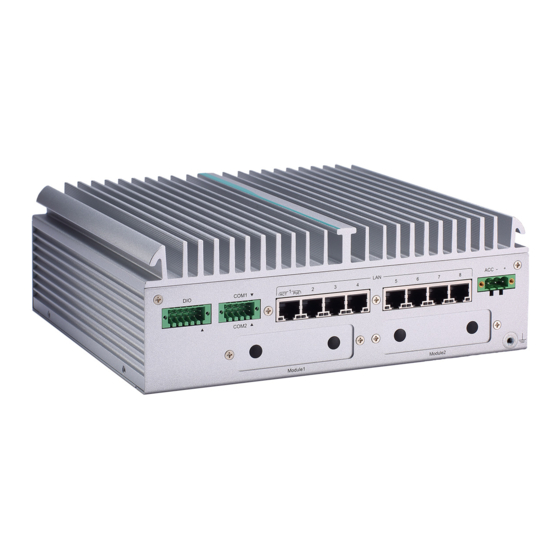
Page 14: I/O Outlets
UST510-52B-FL Series user’s Manual 1.4 I/O Outlets The following figures show I/O outlets on the UST510-52B-FL. Front View Rear View Introduction... -
Page 15: Packing List
(LGA1151), C246, VGA, 2 HDMI, 6-in/2-out DIO, 2 COM, 4 USB 3.0, 8 RJ-45 PoE GbE LAN, 2 SATA drives and ACC 2SATA-TDC ignition Please contact an Axiomtek distributor immediately if any of the abovementioned item is missing. Introduction... - Page 16 UST510-52B-FL Series user’s Manual This page is intentionally left blank. Introduction...
-
Page 17: Section 2 Hardware Installation
UST510-52B-FL Series user’s Manual SECTION 2 HARDWARE INSTALLATION The UST510-52B-FL is convenient for various hardware configurations, such as CPU, DRAM, HDD (Hard Disk Drive), SSD (Solid State Drive), and PCI Express Mini card modules. Section 2 contains guidelines for hardware installation. - Page 18 UST510-52B-FL Series user’s Manual Step 4 CPU installation steps: ⚫ Lift the processor package from shipping media by grasping the substrate edges. ⚫ Scan the processor package’s gold pads for any presence of foreign material. ⚫ Locate connection 1 indicator on the processor which aligns with connection 1 indicator chamfer on the socket, and notice processor keying features that line up with posts along socket walls.
- Page 19 UST510-52B-FL Series user’s Manual Step 5 When installing the CPU, pay attention to the CPU’s orientation and align the arrow mark on the CPU with the arrow key on the socket (Step 4). And apply the thermal pad on top of the processor.
-
Page 20: Installing So-Dimm
UST510-52B-FL Series user’s Manual 2.2 Installing SO-DIMM Step 1 Turn off the system and unplug the power cord. Step 2 Loosen all screws to remove the top cover. Step 3 Locate the dual SO-DIMM sockets on the main board. Step 4 Put the thermal pad on the slot. - Page 21 UST510-52B-FL Series user’s Manual Step 5 Insert the gold colored contact of the memory module into the socket and push the module’s two end latches down until the module is locked in place. Put the thermal pad on the DDR module again.
-
Page 22: Installing Thermal Pads
UST510-52B-FL Series user’s Manual 2.3 Installing thermal pads Step 1 Turn off the system and unplug the power cord. Step 2 Loosen all screws to remove the top cover. Step 3 Put the thermal pads on the secant locations. 【Note】... -
Page 23: Installing 2.5" Sata Device
UST510-52B-FL Series user’s Manual 2.4 Installing 2.5” SATA Device 2.4.1 Installing 2.5” SATA Device Step 1 Turn off the system and unplug the power cord. Step 2 Loosen all of the SATA drive tray’s screws. Step 3 Extract the SATA drive tray. One drive tray can be used to install two SSD/HDD drives. -
Page 24: Installing Mini Pcie / M.2 Module
UST510-52B-FL Series user’s Manual 2.5 Installing Mini PCIe / M.2 Module 2.5.1 Installing Mini PCIe / M.2 Module Step 1 Turn off the system and unplug the power cord. Step 2 Turn the system upside down and loosen the SATA trays. - Page 25 UST510-52B-FL Series user’s Manual Step 7 Insert the M.2 3050/3052 B key card and fasten the screws as shown. Step 8 Place the cover back onto the bottom of the system and fasten all screws firmly. Step 9 Slide the SATA trays back and fasten screws firmly to complete the installation.
- Page 26 UST510-52B-FL Series user’s Manual Hardware Installation...
-
Page 27: Installing The Wall Mount Kit
UST510-52B-FL Series user’s Manual 2.6 Installing the Wall Mount Kit 2.6.1 Installing the Wall Mount Kit Step 1 Turn off the system and unplug the power cord. Step 2 Locate the wall mount screw holes on both sides of the system. -
Page 28: Installing The Cable Fixing Plate
UST510-52B-FL Series user’s Manual 2.7 Installing the Cable Fixing Plate 2.7.1 Installing the HDMI Cable Fixing Plate Step 1 Turn off the system and unplug the power cord. Step 2 To fasten the HDMI cable fixing plate to the system, position the hole on the plate against the hole on the system, insert the screw into the holes, and turn the screw tightly to fasten the plate, as shown below. -
Page 29: Section 3 Button & Connector Settings
UST510-52B-FL Series user’s Manual SECTION 3 BUTTON & CONNECTOR SETTINGS 3.1 Buttons 3.1.1 Power Button The power button is located on the I/O side. It allows users to control power on/off state of the UST510-52B-FL. Note: Refer to APPENDIX C for instructions on power button settings for Windows. -
Page 30: Connectors
UST510-52B-FL Series user’s Manual 3.2 Connectors Please refer to pin assignments below: 3.2.1 DC-in Power Connector ⚫ Wide-range 9 - 36VDC (typical 12/24VDC) power input with terminal block. ⚫ OVP and RVP protection. ⚫ Supports Axiomtek Smart Ignition. Pins Signals... -
Page 31: Hdmi Connector
UST510-52B-FL Series user’s Manual 3.2.2 HDMI Connector The HDMI (High-Definition Multimedia Interface) Rev1.4b is a compact digital interface which is capable of transmitting high-definition video and high-resolution audio over a single cable. Pin definition follows HDMI Type A standard. 3.2.3 Serial Port Connector (COM1~COM2) ⚫... -
Page 32: Ethernet & Power Over Ethernet Connector
UST510-52B-FL Series user’s Manual 3.2.4 Ethernet & Power over Ethernet Connector RJ45 The board has 9 RJ-45 connectors. The front-side-panel LAN is designed based on the Intel i211 controller. Front-side-panel LAN Pins LAN Signal Pins LAN Signal MDI0+ MDI2+ MDI0-... -
Page 33: Usb 3.0 Connector
UST510-52B-FL Series user’s Manual NOTE: If PoE power supply exceeds power budget, the PoE LED will start blinking. 3.2.5 USB 3.0 Connector The Universal Serial Bus connectors are compliant with USB 3.0 (5 GB/s), ideal for connecting USB peripherals such as scanners, cameras and other USB devices. Pin definition follows USB Implementers Forum, Inc. -
Page 34: Sim Card Slots (S1~S2)
UST510-52B-FL Series user’s Manual Signals +5V level 3.2.10 SIM Card Slots (S1~S2) The UST510-52B-FL includes two SIM slots on the front side of the system for inserting a SIM card. It is mainly used for 3G/4G/LTE wireless network applications on CN1 2 and CN15. - Page 35 UST510-52B-FL Series user’s Manual No use No use No use No use +1.5V No use No use +3.3VSB Half-Size (CN17) CN17 applies to USB2.0 and SATA (mSATA) signals and complies with PCI-Express Mini Card Spec. V1.2. Thus, users can install an mSATA card into this slot.
-
Page 36: Key E Connector (Cn18)
UST510-52B-FL Series user’s Manual 3.2.12 M.2 Key E Connector (CN18) The system comes with one M.2 Key E connector (Wi-Fi & Bluetooth) Pins Signals Pins Signals +3.3V +3.3V USB#14_D+ USB#14_D- PCM_CRF_RST[*] CNV_WR_1_DN[*] CNV_WR_1_DP[*] PCMOUT_CLKREQ0[*] CNV_WR_0_DN[*] CNV_WR_0_DP[*] UART_BT_WAKE[*] CNV_BRI_RSP[*] CNV_WR_CLK_DN[*] CNV_WR_CLK_DP[*]... -
Page 37: 3050/3052 Key B (Cn14)
UST510-52B-FL Series user’s Manual 3.2.13 M.2 3050/3052 Key B (CN14) The system comes with one M.2 Key B connector (LTE & SIM). Signal Signal Signal Signal CONFIG_3 +3.3V +3.3V Full Card PWR USB_D+ W_DISABLE1# USB_D- GPIO_9 Key B Key B... - Page 38 UST510-52B-FL Series user’s Manual CONFIG_1 +3.3V +3.3V +3.3V CONFIG_2 Button & Connector Settings...
-
Page 39: Section 4 Bios Setup Utility
UST510-52B-FL Series user’s Manual SECTION 4 BIOS SETUP UTILITY This section provides users with detailed description s in terms of how to set up basic system configurations through the BIOS setup utility. 4.1 Starting To enter the setup screens, follow the steps below: Turn on the computer and press the <Del>... -
Page 40: Navigation Keys
UST510-52B-FL Series user’s Manual 4.2 Navigation Keys The BIOS setup/utility uses a key-based navigation system called hot keys. Most of the BIOS setup utility hot keys can be used at any time during the setup navigation process. These keys include <F1>, <F2>, <Enter>, <ESC>, <Arrow> keys, and so on. -
Page 41: Main Menu
UST510-52B-FL Series user’s Manual 4.3 Main Menu The Main Menu screen is the first screen users see when entering the setup utility. Users can always return to the Main setup screen by selecting the Main tab. System Time/Date can be set up as described below. -
Page 42: Advanced Menu
UST510-52B-FL Series user’s Manual 4.4 Advanced Menu The Advanced menu also allows users to set configuration of the CPU and other system devices. Users can select any items in the left frame of the screen to go to sub menus: MiniCard Switch ►... - Page 43 UST510-52B-FL Series user’s Manual Mini Card switch Use this to select Mini Card setting, default is “PCIE”. BIOS Setup Utility...
- Page 44 UST510-52B-FL Series user’s Manual CPU Configuration This screen shows the CPU version and its detailed information. Intel Virtualization Technology It allows a hardware platform to run multiple operating systems separately and simultaneously, enabling one system to virtually function as several systems.
- Page 45 UST510-52B-FL Series user’s Manual NCT6106D Super IO Configuration Use this screen to select options for the NCT6106D Super IO Configurations, and change the value of the selected option. A description of the selected item appears on the right side of the screen.
- Page 46 UST510-52B-FL Series user’s Manual Serial Port 1 & 2 Configuration BIOS Setup Utility...
- Page 47 UST510-52B-FL Series user’s Manual Select Mode Use this option to set RS-232/RS-422/RS-485 mode. BIOS Setup Utility...
- Page 48 UST510-52B-FL Series user’s Manual NCT6106D Hardware Monitor This screen displays the temperatures of system and CPU and system voltages (VCORE, +3.3V, +12V and +5V). BIOS Setup Utility...
- Page 49 UST510-52B-FL Series user’s Manual SATA & RST Configuration SATA Mode Selection AHCI (Advanced Host Controller Interface) mode is how SATA controller(s) operate. Serial ATA Port 0~3 It shows the device installed in connector SATA0~3. BIOS Setup Utility...
- Page 50 UST510-52B-FL Series user’s Manual Trusted Computing This sub-menu will allow you to enable/disable Trusted Platform Module (TPM) support and to configure the TPM State. Select Trusted Computing and press Enter to access the sub-menu. Select the Security Device Support item to enable the TPM device.
- Page 51 UST510-52B-FL Series user’s Manual USB Configuration This screen specifies USB settings. USB Devices Display all detected USB devices. BIOS Setup Utility...
- Page 52 UST510-52B-FL Series user’s Manual Device Configuration The DIO Modification default setting is “disable”. If the setting is changed to “enable”, you can load manufacture default and program DIO setting. (Please refer to below graphics.) BIOS Setup Utility...
- Page 53 UST510-52B-FL Series user’s Manual BIOS Setup Utility...
- Page 54 UST510-52B-FL Series user’s Manual BIOS Setup Utility...
- Page 55 UST510-52B-FL Series user’s Manual Smart Ignition Configuration The Smart Ignition Management setting includes Axiomtek DIO settings. Press Enter to access the sub-menu. Calculated based on the 24-hour military-time clock. BIOS menu item Description Ignition Enabled Management Switch to In-Vehicle mode...
- Page 56 UST510-52B-FL Series user’s Manual System will not turn on automatically when power is connected or when power resumes from a power failure Set system on/off timing and voltage threshold levels Advance Setting Save the current settings to PSU Save Settings...
- Page 57 UST510-52B-FL Series user’s Manual (Low Voltage) drops below the value defined in [Low Voltage Trigger]. The system will be forced to turn off once timer completes countdown. IGN Trigger Enable IGN signal will trigger [System Turn On Delay] and [Shutdown Delay].
- Page 58 UST510-52B-FL Series user’s Manual Version Display PoE Controller FW version. Power Budget Display current total power budget on all ports. Note: Please be advised that, when setting up power budget, the power budget must not smaller than the sum up of Power Device (PD) operating watts and Power Classifications Watts.
- Page 59 UST510-52B-FL Series user’s Manual Port1~Port8 Enable/Disable a specific POE port and display all port status. BIOS Setup Utility...
-
Page 60: Chipset Menu
UST510-52B-FL Series user’s Manual 4.5 Chipset Menu The Chipset menu allows users to change the advanced chipset settings. Users can select any of the items in the left frame of the screen to go to the sub menus: ► System Agent (SA) Configurations ►... - Page 61 UST510-52B-FL Series user’s Manual System Agent (SA) Configurations BIOS Setup Utility...
- Page 62 UST510-52B-FL Series user’s Manual Memory Configuration Use this item to refer to the information related to system memory. This screen shows the system memory information. BIOS Setup Utility...
- Page 63 UST510-52B-FL Series user’s Manual PCH-IO Configuration This screen shows ME Firmware information. BIOS Setup Utility...
- Page 64 UST510-52B-FL Series user’s Manual Security Menu Administrator Password This item indicates whether an administrator password has been set (installed or uninstalled). User Password This item indicates whether a user password has been set (installed or uninstalled). BIOS Setup Utility...
-
Page 65: Boot Menu
UST510-52B-FL Series user’s Manual 4.6 Boot Menu The Boot menu allows users to change boot options of the system, providing UEFI, Legacy, and Compatible modes to select from. The default setting boot mode is [UEFI Mode]. (Please refer to below graphics.) - Page 66 UST510-52B-FL Series user’s Manual Setup Prompt Timeout Use this item to set up number of seconds to wait for setup activation key where 65535(0xFFFF) means indefinite waiting. Bootup NumLock State Use this item to select the power-on state for the keyboard NumLock.
-
Page 67: Save & Exit Menu
UST510-52B-FL Series user’s Manual 4.7 Save & Exit Menu The Save & Exit menu allows users to determine whether or not to accept their modifications to the system configuration, or to keep default values for optimal fail-safe performance. (Please refer to below graphics.) - Page 68 UST510-52B-FL Series user’s Manual BIOS menu Description item Save Changes When users have completed the system configuration changes, select and Exit this option to leave Setup and return to Main Menu. Select Save Changes and Exit from the Save & Exit menu and press <Enter>. Select Yes to save changes and exit.
-
Page 69: Appendix Awatchdog Timer
How to Use the Watchdog Timer The user can configure the watchdog timer using the watchdog function included in the AXVIEW2.0 software developed by Axiomtek or using the debug.exe software released by Microsoft. NOTE: The related tool for setting WDT will not be available on the official downloads area. - Page 70 UST510-52B-FL Series user’s Manual Disable watchdog timer STEP Sample code Note 1. Enter configuration mode O 2E 87 Un-lock super I/O O 2E 87 Un-lock super I/O 2. Select logic device O 2E 07 Select logic register O 2F 08 Switch to WDT device 3.
-
Page 71: Appendix Bdigital I/O
UST510-52B-FL Series user’s Manual APPENDIX B DIGITAL I/O Digital I/O Specification Digital Input: Input channels: 6, sink/source type Input voltage: 0 to 30VDC Input level for dry contacts: Logic level 0: close to ground Logic level 1: open Input level for wet contacts: Logic level 1: +/-3VDC max. - Page 72 UST510-52B-FL Series user’s Manual Digital I/O...
- Page 73 UST510-52B-FL Series user’s Manual Digital Input Wiring Digital I/O...
- Page 74 UST510-52B-FL Series user’s Manual Digital Output Wiring Digital I/O...
-
Page 75: Appendix C Power Button Setting For Windows
UST510-52B-FL Series user’s Manual APPENDIX C POWER BUTTON SETTING FOR WINDOWS To enable the power button function, go to the console of the PC and then follow below figures to complete the setting. Power Button Setting For Windows... - Page 76 UST510-52B-FL Series user’s Manual Please check if the action of pressing the power button is “Shut down” to let ACC work normally and prevent unexpected hard shut down. Power Button Setting For Windows...
- Page 77 UST510-52B-FL Series user’s Manual Power Button Setting For Windows...
Need help?
Do you have a question about the UST510-52B-FL Series and is the answer not in the manual?
Questions and answers