Table of Contents
Advertisement
Quick Links
Advertisement
Table of Contents

Subscribe to Our Youtube Channel
Related Manuals for AXIOMTEK eBOX640-521-FL Series


Summary of Contents for AXIOMTEK eBOX640-521-FL Series
- Page 1 Series Embedded System User’s Manual...
-
Page 2: Disclaimers
Axiomtek does not make any commitment to update any information in this manual. Axiomtek reserves the right to change or revise this document and/or product at any time without notice. No part of this document may be reproduced, stored in a retrieval system, or transmitted in any forms or by any means, electronic, mechanical, photocopying, recording, among others, without prior written permissions of Axiomtek Co., Ltd. -
Page 3: Safety Precautions
Safety Precautions Before getting started, please read the following important safety precautions. The eBOX640-521-FL does not come with an operating system which must be loaded first before installation of any software into the computer. Be sure to ground yourself to prevent static charge when installing any internal components. -
Page 4: Classification
Classification Degree of production against electric shock: not classified Degree of protection against ingress of dust: IP40 Equipment not suitable for use in the presence of a flammable anesthetic mixture with air, oxygen or nitrous oxide. Mode of operation: Continuous... -
Page 5: General Cleaning Tips
General Cleaning Tips Please keep the following precautions in mind while understanding the details fully before and during any cleaning of the computer and any components within. A piece of dry cloth is ideal to clean the device. Be cautious of any tiny removable components when using a vacuum cleaner to absorb dirt on the floor. -
Page 6: Scrap Computer Recycling
Scrap Computer Recycling Please inform the nearest Axiomtek distributor as soon as possible for suitable solutions in case computers require maintenance or repair; or for recycling in case computers are out of order. Trademarks Acknowledgments Axiomtek is a trademark of Axiomtek Co., Ltd. -
Page 7: Table Of Contents
Table of Contents Disclaimers ......................ii Safety Precautions ....................iii Classification ......................iv General Cleaning Tips ................... v Scrap Computer Recycling ................... vi SECTION 1 INTRODUCTION ................ 1 General Description ................1 System Specifications ............... 2 1.2.1 CPU ........................2 1.2.2 I/O System ...................... - Page 8 3.3.12 Front Panel Connector (CN34) ..............29 SECTION 4 BIOS SETUP UTILITY .............. 31 Starting ..................... 31 Navigation Keys ................31 Main Menu ..................32 Advanced Menu ................33 Chipset Menu ................... 44 Security Menu .................. 49 Boot Menu ..................50 Save &...
-
Page 9: Section 1 Introduction
Series User’s Manual SECTION 1 INTRODUCTION This section contains general information and detailed specifications of the eBOX640-521-FL. Section 1 includes the following sections: General Description System Specifications Dimensions I/O Outlets Packing List Model List... -
Page 10: System Specifications
Series User’s Manual System Specifications 1.2.1 ® ® Core™ i7/i5/i3 & Celeron LGA1151 socket 8th/9th gen Intel processors (CPU TDP max. up to 35W ) Chipset ® Intel H310 BIOS American Megatrends Inc. UEFI (Unified Extensible Firmware Interface) BIOS. -
Page 11: System Specification
3.6 kg (7.94 lb) with package Dimensions 195 mm (7.67") (W) x 210.3 mm (8.27") (D) x 80 mm (3.14") (H) 1.2.4 Driver CD Content Please download the following eBOX640-521-FL drivers from the Axiomtek official website. Chipset Ethernet Graphic ... -
Page 12: Dimensions
Series User’s Manual Dimensions The following diagrams show dimensions and outlines of the eBOX640-521-FL. 1.3.1 System Dimensions Introduction... -
Page 13: Wall Mount Bracket Dimensions
Series User’s Manual 1.3.2 Wall mount Bracket Dimensions Introduction... - Page 14 Series User’s Manual Instructions Step 1: Screw the two pieces of wall-mount kits to the bottom plate of the device. Total four screws (metric 3 x6) are required. Step 2: Use the device, with the wall mount plate attached, as a guide to mark the correct locations of the four screws.
-
Page 15: I/O Outlets
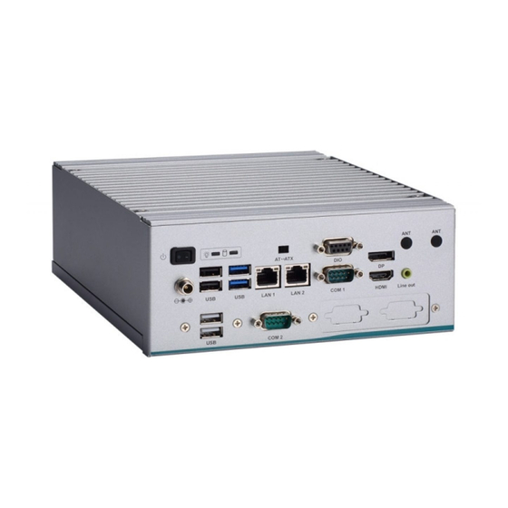
Series User’s Manual I/O Outlets The following figures show I/O outlets on the front of the eBOX640-521-FL. Front View Side View Power button Line out LEDs (power, HDD) HDMI port Flexible IO W indow LAN 1 (default : 2 x DB9 half cut bracket) -
Page 16: Packing List
Fanless embedded system with LGA1151 8th gen Intel ® ® Core™ i7/i5/i3 & Celeron eBOX640-521-FL-DC processor, Intel H310, HDMI, DisplayPort, 6 USB, 2 COM, M.2 slot and 19VDC Please contact Axiomtek’s distributors immediately in case any abovementioned items are missing. Introduction... -
Page 17: Section 2 Hardware Installation
Series User’s Manual SECTION 2 HARDWARE INSTALLATION The eBOX640-521-FL is convenient for your various hardware configurations, such as HDD (Hard Disk Drive), SSD (Solid State Drive), Long-DIMM or PCI Express Mini Card modules. Section 2 will show how to install the hardware. - Page 18 Series User’s Manual Step 5 Installation steps of the CPU processor Lift the processor package from shipping media by grasping the substrate edges. Scan the processor package gold pads for any presence of foreign material. Locate connection 1 indicator on the processor which aligns with connection 1 indicator chamfer on the socket, and notice processor keying features that line up with posts along socket walls.
- Page 19 Series User’s Manual Step 6 Installation steps of the CPU processor Align pins of the CPU with pin holes of the socket. Be careful of the CPU’s orientation that users need to align the arrow mark on the CPU with the arrow key on the socket.
-
Page 20: Installation Of So-Dimm Memory
Series User’s Manual Installation of SO-DIMM Memory Step 1 Turn off the system, and unplug the power cord. Step 2 On the top heatsink, locate the four screws used to fasten the heatsink to the chassis. Step 3 Loosen the screws to remove the top heatsink and locate the two SO-DIMM sockets on the main board. -
Page 21: Installation Of The Express Mini Card
Series User’s Manual Installation of the Express Mini Card Step 1 Turn off the system, and unplug the power cord. Step 2 Turn the system upside down to locate the two screws at the rear side, and then loosen the two screws. -
Page 22: Installation Of The 2.5" Sata Device
Series User’s Manual Installation of the 2.5" SATA Device Step 1 Turn off the system, and unplug the power adaptor. Step 2 Turn the system upside down to locate the two screws at the rear side, and then loosen the two screws. -
Page 23: Installation Of Flexible I/O Modules
Series User’s Manual Installation of Flexible I/O Modules The eBOX640-521 provides an optional I/O window for customers to add flexible I/O kits via mPCIe interface. For details of the available modules listed below, please refer to their respective quick manuals. - Page 24 Series User’s Manual Step 4 Assemble the I/O cable to the I/O bracket, and then fasten the dual screws of the flexible I/O Window to fix the I/O bracket to the I/O window. Step 5 Connector the cable to the mini card slot.
-
Page 25: Section 3 Jumper & Connector Settings
Series User’s Manual SECTION 3 JUMPER & CONNECTOR SETTINGS Proper jumper settings configure the eBOX640-521-FL to meet various application needs. Hereby all jumpers settings along with their default settings are listed for devices onboard. Locations of Jumpers & Connectors MANO521 Top Side Jumper &... - Page 26 Series User’s Manual MANO521 Bottom Side 【Note】 It is strongly recommended that any unmentioned jumper settings should not be modified without instructions by Axiomtek FAEs. Any modifications without instructions might cause system failure. Jumper & Connector Settings...
-
Page 27: Summary Of Jumper Settings
Series User’s Manual Summary of Jumper Settings Proper jumper settings configure the eBOX640-521-FL to meet various application purposes. A table of all jumpers and their default settings is listed below. MANO521 Jumpers Descriptions Settings CN27 Pin 1: DCD# 3-5 Close... -
Page 28: Com2 Data/Power Select (Jp1)
Series User’s Manual 3.2.1 COM2 Data/Power Select (JP1) The COM2 port has +5V level power capability on DCD# and +12V level on RI# by setting JP1. Functions Settings Power: Set CN27 pin 1 to +5V level 1-3 close Data: Set CN27 pin 1 to DCD# (Default) -
Page 29: Connectors
Connectors connect the board with other parts of the system. Loose or improper connection might cause problems. Make sure all connectors are properly and firmly connected. Here is a table summarizing all connectors on the eBOX640-521-FL series. External Connectors Sections... -
Page 30: Dc Jack Power Connector (Cn1)
Series User’s Manual 3.3.1 DC Jack Power Connector (CN1) The CN1 is a DC jack with screw supporting the 12V, 19- 24VDC power input connector. Firmly insert an adapter with at least 90W power supply into this connector. Loose... -
Page 31: Ethernet Connector (Cn4 & Cn5)
Series User’s Manual 3.3.4 Ethernet Connector (CN4 & CN5) The motherboard comes with two high performance plug and play Ethernet interfaces (RJ-45) which are fully compliant with the IEEE 802.3 standard. Connection can be established by plugging one end of the Ethernet cable into this RJ-45 connector and the other end to a 1000/100/10-Base-T hub. -
Page 32: Com1 D-Sub Connector (Cn6)
Series User’s Manual 3.3.5 COM1 D-Sub Connector (CN6) This connector is a standard D-Sub connector for COM1 serial port interface which is selectable for RS-232/422/485 mode by BIOS setting (see section 4.4). The pin assignments of RS-232/422/485 are listed in table below. -
Page 33: Displayport And Hdmi Connector (Cn8)
Series User’s Manual 3.3.7 DisplayPort and HDMI Connector (CN8) The CN8 is a stacked connector comprising an upper connector for DisplayPort++ interface and a lower connector for HDMI interface. Pins Signals Pins Signals DP_TX0_P HDMI OUT_DATA2+ DP_TX0_N HDMI OUT_DATA2-... -
Page 34: 8-Ch Dio Connecotr (Cn10)
Series User’s Manual 3.3.9 8-CH DIO Connecotr (CN10) This digital I/O has 8 bits (DIO0~7) by CN10 connector. Each bit can be set to function as input or output by software programming. Description DIO0 (GPI70, 0xA06, Bit0, H) DIO1 (GPI71, 0xA06, Bit1, H) -
Page 35: Key E Connector (Cn15)
Series User’s Manual 3.3.10 M.2 Key E Connector (CN15) The system comes with one M.2 Key E connector (Wi-Fi & Bluetooth). Pins Signals Pins Signals +3.3V +3.3V USB#14_D+ USB#14_D- PCM_CRF_RST[*] CNV_W R_1_DN[*] CNV_W R_1_DP[*] PCMOUT_CLKREQ0[*] CNV_W R_0_DN[*] CNV_W R_0_DP[*]... -
Page 36: Express Mini Card Slot (Cn16)
Series User’s Manual 3.3.11 Express Mini Card Slot (CN16) The mini card interface is available through connector CN16. Pins Signals Pins Signals W AKE# +3.3VAUX +1.5V CLKREQ# UIM_PW R UIM_DAT REFCLK- UIM_CLK REFCLK+ UIM_REST UIM_VPP +3.3VAUX (pull-high PERST# SATA0_RX_DP +3.3VAUX... -
Page 37: Front Panel Connector (Cn34)
Series User’s Manual 3.3.12 Front Panel Connector (CN34) The CN34 is a 2x7-pin (pitch=2.54mm) header for front panel interface. Pins Signals Pins Signals Power LED+ SPK- Buzzer Power LED- SPK+ PW R- PW R+ RESET- RESET+ HD LED- HD LED+ Power LED Pin 1 connects anode (+) of LED and pin 5 connects cathode(-) of LED. - Page 38 Series User’s Manual This page is intentionally left blank. Jumper & Connector Settings...
-
Page 39: Section 4 Bios Setup Utility
Series User’s Manual SECTION 4 BIOS SETUP UTILITY This section provides users with detailed description how to set up basic system configuration through the BIOS setup utility. Starting To enter the setup screens, follow the steps below: Turn on the computer and press the <Del> key immediately. -
Page 40: Main Menu
Series User’s Manual Main Menu The Main Menu screen is the first screen users see when entering the setup utility. Users can always return to the Main setup screen by selecting the Main tab. System Time/Date can be set up as described below. The Main BIOS setup screen is also shown below. -
Page 41: Advanced Menu
Series User’s Manual Advanced Menu The Advanced menu also allows users to set configuration of the CPU and other system devices. You can select any of the items in the left frame of the screen to go to the sub menus: ►... - Page 42 Series User’s Manual IT8625 Super IO Configuration Users can use this screen to select options for the Super IO Configuration, and change the value of the selected option. A description of the selected item appears on the right side of the screen.
- Page 43 Series User’s Manual BIOS Setup Utility...
- Page 44 Series User’s Manual Hardware Monitor This screen monitors hardware health status. BIOS Setup Utility...
- Page 45 Series User’s Manual Trust Computing This screen provides function for specifying the TPM settings. Security Device Support Enable or disable BIOS support for security device. OS will not show security device. TCG EFI protocol and INT1A interface will not be available.
- Page 46 Series User’s Manual TPM Device Selection: Select TPM device: - dTPM: External extended Infineon’s TPM . Pending operation Schedule an operation for the security device, see image below. - None - TPM Clear: Clear all data secured by TPM.
- Page 47 Series User’s Manual ACPI Settings ACPI Sleep State When the suspend button is pressed, the ACPI (Advanced Configuration and Power Interface) sleep state is S3 (Suspend to RAM). BIOS Setup Utility...
- Page 48 Series User’s Manual CPU Configurations This screen shows the CPU version and its detailed information. Intel Virtualization Technology Enable or disable Intel Virtualization Technology. When enabled, a VMM (Virtual Machine Mode) can utilize the additional hardware capabilities. It allows a platform to run multiple operating systems and applications independently, hence enabling a single computer system to work as several virtual systems.
- Page 49 Series User’s Manual SATA & RTS Configuration During system boot up, BIOS automatically detects the presence of SATA devices. In the SATA Configuration menu, you can see the currently installed hardware in the SATA ports. SATA Controller(s) Enable or disable the SATA Controller feature. The default is Enabled.
- Page 50 Series User’s Manual PCH-HW This screen shows ME Firmware information. BIOS Setup Utility...
- Page 51 Series User’s Manual USB Configurations USB Devices Display all detected USB devices. BIOS Setup Utility...
-
Page 52: Chipset Menu
Series User’s Manual Chipset Menu The Chipset menu allows users to change the advanced chipset settings. Users can select any of the items in the left frame of the screen to go to the sub menus: ► PCH-IO Configuration ►... - Page 53 Series User’s Manual System Agent(SA) Configuration This screen allows users to configure System Agent (SA) parameters. For items marked with “ , please press <Enter> for more options. Graphics Configuration Select to open sub menu for parameters related to graphics configuration.
- Page 54 Series User’s Manual Graphic Configuration Primary IGFX Boot Display Select the video device which will be activated during POST (Power-On Self Test). The secondary boot display selection will appear based on your selection. Secondary IGFX Boot Display After selecting other than “AUTO” on “Primary IGFX Boot Display”, the Secondary IGFX ...
- Page 55 Series User’s Manual Memory Configuration This screen shows the system memory information. BIOS Setup Utility...
- Page 56 Series User’s Manual PCH- IO Configuration This screen allows you to set PCH parameters. BIOS Setup Utility...
-
Page 57: Security Menu
Series User’s Manual Security Menu The Security menu allows users to change the security settings for the system. Administrator Password This item indicates whether an administrator password has been set (installed or uninstalled). User Password This item indicates whether a user password has been set (installed or uninstalled). -
Page 58: Boot Menu
Series User’s Manual Boot Menu The Boot menu allows users to change boot options of the system. Setup Prompt Timeout This item sets number of seconds to wait for setup activation key. Options:1 (Default) Bootup NumLock State Use this item to select the power-on state for the keyboard NumLock. -
Page 59: Save & Exit Menu
Series User’s Manual Save & Exit Menu The Save & Exit menu allows users to load system configuration with optimal or fail-safe default values. Save Changes and Exit When users have completed the system configuration changes, select this option to leave Setup and return to Main Menu. - Page 60 Series User’s Manual Save Changes When completed the system configuration changes, select this option to save changes. Select Save Changes from the Save & Exit menu and press <Enter>. Select Yes to save changes. Discard Changes Select this option to quit Setup without making any permanent changes to the system configuration.
-
Page 61: Appendix Awatchdog Timer
Series User’s Manual APPENDIX A WATCHDOG TIMER About Watchdog Timer Software stability is major issue in most application. Some embedded systems are not watched by human for 24 hours. It is usually too slow to wait for someone to reboot when computer hangs. - Page 62 Series User’s Manual This page is intentionally left blank. Watchdog Timer...
-
Page 63: Appendix Btpm Settings
Series User’s Manual APPENDIX B TPM SETTINGS 1. Setup BitLocker Drive Encryption main storage. Press <Win + R> and type “Control Panel”, then select BitLocker Drive Encryption. TPM Settings... - Page 64 Series User’s Manual 2. Insert an external storage device, for example USB Storage. To back up BitLocker recovery key in a new file and save it to the USB Storage. Digital I/O Settings...
- Page 65 Series User’s Manual 3. Please follow the steps below to encrypt your storage device: TPM Settings...
- Page 66 Series User’s Manual Now, the system prompts that the operating system drive encryption is in progress, and the encryption progress is checked. Digital I/O Settings...
- Page 67 Series User’s Manual Select and click the icon in the lower right corner to complete the encryption. TPM Settings...
- Page 68 Series User’s Manual 4. Confirm the completion of encryption. Digital I/O Settings...
- Page 69 Series User’s Manual 5. Disable TPM function in BIOS Setup Utility. 6. When the system is powered on and you see the following screen, it means the TPM module function is working fine. Note that BitLocker cannot be executed if your system does not have TPM function.
- Page 70 Series User’s Manual System with no TPM function support is demonstrated as below: 【Note】 TPM information is not found in Device Manager. When trying to turn on Bitlocker, the following error message shows up. Digital I/O Settings...
- Page 71 Series User’s Manual TPM Settings...
- Page 72 Series User’s Manual This page is intentionally left blank. Digital I/O Settings...
-
Page 73: Appendix Cdigital I/O Settings
DIO4 (GPI74, 0xA06, Bit4, H) DIO5 (GPI75, 0xA06, Bit5, H) DIO6 (GPI76, 0xA06, Bit6, H) DIO7 (GPI77, 0xA06, Bit7, H) AP Programming ※Please download the DIO demo source code from AXIOMTEK website for programming AP. Step 1 Run DIO_Demo.exe Digital I/O Settings... - Page 74 Series User’s Manual Step 2 setup input or output Step 3 Read status of input Setup low/high level of output Digital I/O Settings...
Need help?
Do you have a question about the eBOX640-521-FL Series and is the answer not in the manual?
Questions and answers