Table of Contents
Advertisement
Quick Links
Advertisement
Table of Contents

Related Manuals for AXIOMTEK tBOX810-838-FL Series


Summary of Contents for AXIOMTEK tBOX810-838-FL Series
- Page 1 Series Embedded System User’s Manual...
-
Page 2: Disclaimers
Axiomtek does not make any commitment to update the information in this manual. Axiomtek reserves the right to change or revise this document and/or product at any time without notice. No part of this document may be reproduced, stored in a retrieval system, or transmitted, in any form or by any means, electronic, mechanical, photocopying, recording, or otherwise, without the prior written permission of Axiomtek Co., Ltd. -
Page 3: Safety Precautions
Safety Precautions Before getting started, please read the following important safety precautions. User should not modify any unmentioned jumper settings without Axiomtek FAE’s instruction. Any modifications without instruction might cause system damaged. Operating system follows the configuration you had in tBOX810-838-FL. -
Page 4: Classification
Classification Degree of production against electric shock: not classified Degree of protection against the ingress of water: IP40 Equipment not suitable for use in the presence of a flammable anesthetic mixture with air or with oxygen or nitrous oxide. Mode of operation: Continuous General Cleaning Tips You may need the following precautions before you begin to clean the computer. - Page 5 Cleaning Tools: Although many companies have created products to help improve the process of cleaning your computer and peripherals users can also use household items to clean their computers and peripherals. Below is a listing of items you may need or want to use while cleaning your computer or computer peripherals.
- Page 6 If the computer equipments need the maintenance or are beyond repair, we strongly recommended that you should inform your Axiomtek distributor as soon as possible for the suitable solution. For the computers that are no longer useful or no longer working well, please contact your Axiomtek distributor for recycling and we will make the proper arrangement.
-
Page 7: Table Of Contents
Table of Contents Disclaimers ......................ii Safety Precautions ....................iii Classification ......................iv CHAPTER 1 INTRODUCTION ............... 1 General Description ................1 System Specifications ............... 2 1.2.1 CPU ........................2 1.2.2 System I/O ......................2 1.2.3 System Specification ..................2 1.2.4 Driver CD Content .................... - Page 8 This page is intentionally left blank. viii...
-
Page 9: Chapter 1 Introduction
Series User’s Manual CHAPTER 1 INTRODUCTION This chapter contains general information and detailed specifications of the tBOX810-838-FL. The Chapter 1 includes the following sections: General Description System Specifications Dimensions I/O Outlets Package List General Description ™... -
Page 10: System Specifications
Series User’s Manual System Specifications 1.2.1 ™ ® Intel Atom E3845 processor (Quad Core, 2M Cache, 1.91 GHz) onboard. ™ ® Intel Atom E3827 processor (Dual Core, 2M Cache, 1.75 GHz) onboard. BIOS American Megatrends Inc. BIOS. -
Page 11: Driver Cd Content
Series User’s Manual Storage Temperature -40°C - +85°C (- 40°F - +176°F) Humidity 10% - 95% (non-condensation) Vibration Endurance 3Grms w/ SSD, (5 - 500Hz, X, Y, Z direction; Random) 1Grms w/ HDD, (5 – 500Hz, X, Y, Z direction; Random) ... -
Page 12: Dimensions
Series User’s Manual Dimensions The following diagrams show you dimensions and outlines of the tBOX810-838-FL. Introduction... -
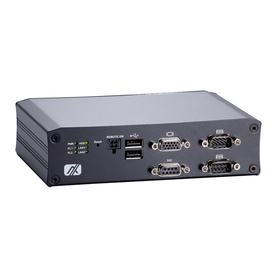
Page 13: I/O Outlets
Series User’s Manual I/O Outlets The following figures show you panoramic view of tBOX810-838-FL. Front View Front View drawing Rear View type #1 type #2 IntrHoduction... - Page 14 Series User’s Manual Rear View drawing type #1 to #4 type #1 Application E26N810100、E26N810102 Vehicle E26N810106、E26N810107、E26N810109 Railway type #2 Application E26N810104、E26N810105、E26N810110 Vehicle E26N810121、E26N810122 type #3 Application E26N810114、E26N810115 Marine type #4 Application E26N810119、E26N810120 Marine Introduction...
-
Page 15: Packing List
M12 power cable (optional) M12 power adapter (optional) Remote switch cable (optional) PCI Express mini card module (optional) If you can not find this package or any items are missing, please contact Axiomtek distributors immediately. IntrHoduction... - Page 16 Series User’s Manual This page is intentionally left blank. Introduction...
-
Page 17: Chapter 2 Hardware Installation
Series User’s Manual CHAPTER 2 HARDWARE INSTALLATION The tBOX810-838-FL is convenient for your various hardware configurations, such as HDD and PCI Express mini card. The chapter 2 will show you how to install the components. HDD/SSD Installation Step 1 Turn off the system, and unplug the power cord. - Page 18 Series User’s Manual Step 4 Connect SATA and power cable with HDD/SSD as shown. Step 5 Fasten bottom cover as shown. Hardware Installation...
-
Page 19: Pci Express Mini Card And Sim Card Installation
Series User’s Manual PCI Express mini card and SIM card Installation Step 1 Turn off the system, and unplug the power cord. Loosen the screws as shown. Step 2 Install the module card and fasten screw as shown. Step 3 Fasten 6x screw on bottom cover as shown. - Page 20 Series User’s Manual This page is intentionally left blank. Hardware Installation...
-
Page 21: Chapter 3 Connector
Series User’s Manual CHAPTER 3 CONNECTOR Connectors Connectors connect the motherboard with other parts of the system. Loose or improper connection might cause problems. Make sure all connectors are properly and firmly connected. 3.1.1 VGA Connector DB15 connector is commonly used for the CRT monitor. -
Page 22: Serial Port Connector
Series User’s Manual 3.1.3 Serial Port Connector The pin definitions of RS-232/422/485 are listed as following matrix. You may select RS- 232/422/485 function in BOS settings. RS-232 RS-422 RS-485 Data- DCD, Data carrier detect Data+ RXD, Receive data TXD, Transmit data... -
Page 23: Led Indicators
Series User’s Manual 3.1.5 LED Indicators Number LED Indicator Function Green Power on Green Programable #1 Green Programable #2 Yellow HDD active Green LAN #1 active Green LAN #2 active 3.1.6 DC Power Input connector There are three pins of the DC-in connector as below. -
Page 24: Lan Connector (Lan#1, Lan#2)
Series User’s Manual 3.1.7 LAN Connector (LAN#1, LAN#2) The M12-8pin LAN connector is A-Code type and able to support 10/100/1000Mbps. 10/100 Mbps 1000 Mbps MDI 2+ MDI 3+ MDI 3- TX - MDI 0- RX + MDI 1+ TX +... -
Page 25: Digital I/O Connector
Series User’s Manual 3.1.8 Digital I/O Connector The tBOX810-838-FL supports a TTL 8bit programmable DIO. Signal DIO0 DIO1 DIO2 DIO3 DIO4 DIO5 DIO6 DIO7 3.1.9 SIM Card Connector The SIM Card slot is a ISO 7816 standard 6-pin connector for PCI Express Mini Card used. -
Page 26: 3.1.10 Pci Express Mini Card Connector
Series User’s Manual 3.1.10 PCI Express mini card Connector The PCI Express mini card connector is able to support a PCI Express x1 link and a USB 2.0 link. Signal Signal WAKE# +3.3VSB No use No use +1.5V CLKREQ#... -
Page 27: Chapter 4 Ami Bios Setup Utility
Series User’s Manual CHAPTER 4 AMI BIOS SETUP UTILITY This chapter provides users with detailed description about how to set up basic system configuration through the AMI BIOS setup utility. Starting To enter the setup screens, follow the steps below: Turn on the computer and press the <Del>... -
Page 28: Navigation Keys
Series User’s Manual Navigation Keys The BIOS setup/utility uses a key-based navigation system called hot keys. Most of the BIOS setup utility hot keys can be used at any time during the setup navigation process. These keys include <F1>, <F10>, <Enter>, <ESC>, <Arrow> keys, and so on. -
Page 29: Main Menu
Series User’s Manual Main Menu System Time/Date You may change the system time and date by this option. Highlight System Time or System Date using the <Arrow> keys. Enter new values through the keyboard. Press the <Tab> key or the <Arrow>... -
Page 30: Advanced Menu
Series User’s Manual Advanced Menu The Advanced menu allows users to set configuration of the CPU and other system devices. You can select any of the items in the left frame of the screen to go to the sub menus: ►... - Page 31 Series User’s Manual NCT6106D Super IO Configuration You may set settings for Super IO configuration by this option, and change the value of the selected option AMI BIOS Setup Utility...
- Page 32 Series User’s Manual DIO Configuration You may set settings for DIO configuration by this option, enable the DIO Modification and get into DIO port 0-9 settings. AMI BIOS Setup Utility...
- Page 33 Series User’s Manual Serial Port 0-1 configuration 1. Serial port: You may enable or disable serial port by this setting. AMI BIOS Setup Utility...
- Page 34 Series User’s Manual 2. Console Redirectino Settings: You may apply different serial port options in this item.. AMI BIOS Setup Utility...
- Page 35 Series User’s Manual NCT6106D H/W Monitor This screen shows the Hardware Health Configuration. AMI BIOS Setup Utility...
- Page 36 Series User’s Manual CPU Configuration This screen shows the CPU Configuration. AMI BIOS Setup Utility...
- Page 37 Series User’s Manual IDE Configuration You may select SATA configuration by this seeeting. AMI BIOS Setup Utility...
- Page 38 Series User’s Manual IDE Configuration You may select SATA configuration by this seeeting. AMI BIOS Setup Utility...
-
Page 39: Chipset Menu
Series User’s Manual Chipset Menu The Chipset menu allows users to change the advanced chipset settings. AMI BIOS Setup Utility... - Page 40 Series User’s Manual USB Configuration This screen shows O/S configuration support AMI BIOS Setup Utility...
-
Page 41: Security Menu
Series User’s Manual Security Menu The Security menu allows users to change the security settings for the system. Administrator Password This item indicates whether a supervisor password has been set. If the password has been installed,『 Installed』 displays. If not, 『Not Installed』displays. -
Page 42: Boot Menu
Series User’s Manual Boot Menu The Boot menu allows users to change boot options of the system. You can select any of the items in the left frame of the screen to go to the sub menus: Setup Prompt Timeout... -
Page 43: Save & Exit Menu
Series User’s Manual Save & Exit Menu The Exit menu allows users to load the system configuration with optimal or failsafe default values. Save Changes and Reset When you have completed the system configuration changes, select this option to leave Setup and reboot the computer so the new system configuration parameters can take effect. - Page 44 Series User’s Manual Restore user Defaults It automatically sets all Setup options to a complete set of default settings when you select this option. The Fail-Safe settings are designed for maximum system stability, but not maximum performance. Select the Fail-Safe Setup options if your computer is experiencing system configuration problems.
-
Page 45: Appendix Awatchdog Timer
Series User’s Manual APPENDIX A WATCHDOG TIMER What is Watchdog Timer The integrated Watchdog Timer can be set up by programming. There are 1~255 levels available. As long as the vaule of timer is set, after enabling, the countdown of the value is starting. - Page 46 Series User’s Manual Sample of Watchdog application Assume there is program A which needs to maintain running in a system. The value of Watchdog Timer must be set bigger than the running time of program A. Then, after the running time of program A is finished, either to disable or to reset watchdog timer.
-
Page 47: Appendix Bignition Configuration
Series User’s Manual APPENDIX B IGNITION CONFIGURATION How to use the PSU tool To format the USB flash drive as “FAT32” format. Step1. To copy the below files “EFI folder” and “PSU.efi” from the PSU tool folder of Driver Step2. - Page 48 Series User’s Manual Ignition Configuration This menu allows users to configure vehicle ignition switch related settings. At first, users need to press the <F8> key and select “COM3” for starting the ignition configuration. Information of the ignition status is as shown below: Switch to the “PSU Configuration”...
- Page 49 Series User’s Manual Voltage Setting Voltage setting is designed to protect the Lead-acid batteries and keep the system from running out of power when the Lead-acid battery is low, so as not to drain the battery. (It is strongly recommended that users should avoid changing the defaults.) (1) Start voltage: When the input voltage meets the specified value, the system starts.
- Page 50 Series User’s Manual Counter Setting (1) Low Voltage Counter: Sets shutdown delay time. (2) Very Low Voltage Counter: Sets force turn off system power delay time. Function Configuration range Default Value Unit Low Voltage Counter 60~600 Very Low Voltage Counter 10~200 (3) ACC-ON Delay (T1): Sets delay time for system power on.
Need help?
Do you have a question about the tBOX810-838-FL Series and is the answer not in the manual?
Questions and answers