Table of Contents
Advertisement
Quick Links
Advertisement
Table of Contents

Related Manuals for AXIOMTEK EBOX640-500-FL Series


Summary of Contents for AXIOMTEK EBOX640-500-FL Series
- Page 1 Series Embedded System User’s Manual...
-
Page 2: Disclaimers
Axiomtek does not make any commitment to update any information in this manual. Axiomtek reserves the right to change or revise this document and/or product at any time without notice. No part of this document may be reproduced, stored in a retrieval system, or transmitted in any forms or by any means, electronic, mechanical, photocopying, recording, among others, without prior written permissions of Axiomtek Co., Ltd. -
Page 3: Safety Precautions
Safety Precautions Before getting started, please read the following important safety precautions. The eBOX640-500-FL does not come with an operating system which must be loaded first before installation of any software into the computer. Be sure to ground yourself to prevent static charge when installing any internal components. -
Page 4: Classification
Classification Degree of production against electric shock: not classified Degree of protection against ingress of water: IP40 Equipment not suitable for use in the presence of a flammable anesthetic mixture with air, oxygen or nitrous oxide. Mode of operation: Continuous... -
Page 5: General Cleaning Tips
General Cleaning Tips Please keep the following precautions in mind while understanding the details fully before and during any cleaning of the computer and any components within. A piece of dry cloth is ideal to clean the device. Be cautious of any tiny removable components when using a vacuum cleaner to absorb dirt on the floor. -
Page 6: Scrap Computer Recycling
Scrap Computer Recycling Please inform the nearest Axiomtek distributor as soon as possible for suitable solutions in case computers require maintenance or repair; or for recycling in case computers are out of order. Trademarks Acknowledgments Axiomtek is a trademark of Axiomtek Co., Ltd. -
Page 7: Table Of Contents
Table of Contents Disclaimers ......................ii Safety Precautions ....................iii Classification ......................iv General Cleaning Tips ................... v Scrap Computer Recycling ................... vi SECTION 1 INTRODUCTION .................. 1 General Description ................1 System Specifications ............... 2 1.2.1 CPU ........................2 1.2.2 I/O System ...................... - Page 8 3.3.11 Power and HDD LED Indicator ..............30 3.3.12 DC power input connector................30 SECTION 4 BIOS SETUP UTILITY ..............31 Starting ..................... 31 Navigation Keys ................31 Main Menu ..................32 Advanced Menu ................33 Chipset Menu ................... 44 Security Menu ..................
-
Page 9: Section 1 Introduction
Series User’s Manual SECTION 1 INTRODUCTION This section contains general information and detailed specifications of the eBOX640-500-FL. The Section 1 includes the following sections: General Description System Specifications Dimensions I/O Outlets Packing List ... -
Page 10: System Specifications
Series User’s Manual Reliable and Stable Design ® The embedded system supports 6th/7th gen Skylake/Kabylake Intel Core i7/ i5/ i3 & ® Celeron CPU, high flexibility and multi-functional design is the best solution for any industrial field applications. -
Page 11: System Specification
Series User’s Manual 1.2.3 System Specification Watchdog Timer 1~255 seconds or minutes; up to 255 levels. Power Supply Input : 10~30 VDC Operation Temperature -10℃~+55℃ (-14°F~+122°F), with W .T. SSD & Memory ... -
Page 12: Dimensions
Series User’s Manual Dimensions The following diagrams show dimensions and outlines of the eBOX640-500-FL. 1.3.1 System Dimensions Introduction... -
Page 13: Wall Mount Bracket Dimensions
Series User’s Manual 1.3.2 Wall mount Bracket Dimensions Instruction Step 1: Screw the two pieces of wall-mount kits to the bottom plate of the device. Total four screws (metric 3 x6) are required. Step 2: Use the device, with wall mount plate attached, as a guide to mark the correct locations of the four screws. -
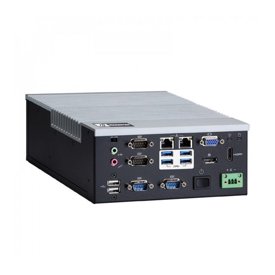
Page 14: I/O Outlets
Series User’s Manual I/O Outlets The following figures show I/O outlets on front of the eBOX640-500-FL. Front View Introduction... -
Page 15: Packing List
& Celeron processors , 1 VGA/HDMI/DisplayPort, 2 eBOX640-500-FL-DC GbE LANs, 4 USB 3.0, 2 USB 2.0,2 COM, PCIe Mini slot and 10~30 VDC PW R input Please contact Axiomtek’s distributors immediately in case any abovementioned items are missing. Introduction... - Page 16 Series User’s Manual This page is intentionally left blank. Introduction...
-
Page 17: Section 2 Hardware Installation
Series User’s Manual SECTION 2 HARDWARE INSTALLATION The eBOX640-500-FL is convenient for your various hardware configurations, such as HDD (Hard Disk Drive), SSD (Solid State Drive), SO-DIMM or PCI Express Mini Card modules. The section 2 will show how to install the hardware. - Page 18 Series User’s Manual Step 5 Installation steps of CPU processors Lift processor package from shipping media by grasping the substrate edges. Scan the processor package gold pads for any presence of foreign material. Locate connection 1 indicator on the processor which aligns with connection 1 indicator chamfer on the socket, and notice processor keying features that line up with posts along socket walls.
-
Page 19: Installation Of So-Dimm Memory
Series User’s Manual Never touch fragile socket contacts to avoid damage and do not touch processor sensitive contacts at any time during installation. Caution Installation of SO-DIMM Memory Step 1 Turn off the system, and unplug the power cord. -
Page 20: Installation Of Express Mini Card
Series User’s Manual Installation of Express Mini Card Step 1 Turn off the system, and unplug the power cord. Step 2 There are eight screws on the top heatsink are used to fasten the heatsink to the chassis. Step 3 Remove the top cover. -
Page 21: Installation Of 2.5" Sat Device
Series User’s Manual Installation of 2.5” SAT Device Step 1 Turn off the system, and unplug the power adaptor. Step 2 Turn the system upside down to locate screws at the rear side, and then loosen two screws. Step 3 Remove the bottom cover and locate SSD/HDD within the red line marked. - Page 22 Series User’s Manual Step 5 Fasten two screws to fix SSD/HDD. Step 6 Connected the SSD/HDD directly and make sure the insertion is complete. Hardware Installation...
-
Page 23: Installation Of Msata Slot
Series User’s Manual Installation of mSATA slot Step 1 Turn off the system, and unplug the power cord. Step 2 Turn the system upside down to locate screws at the rear side, and then loosen two screws. Step 3 Remove the bottom cover. - Page 24 Series User’s Manual This page is intentionally left blank. Hardware Installation...
-
Page 25: Section 3 Jumper & Connector Settings
Series User’s Manual SECTION 3 JUMPER & CONNECTOR SETTINGS Proper jumper settings configure the eBOX640-500-FL to meet various application needs. Hereby all jumpers settings along with their default settings are listed for devices onboard. Locations of Jumpers & Connectors MANO500 Top Side Jumper &... - Page 26 Series User’s Manual MANO500 Bottom Side 【Note】: It is strongly recommended that any unmentioned jumper settings should not be modified without instructions by Axiomtek FAEs. Any modifications without instructions might cause system failure. Jumper & Connector Settings...
-
Page 27: Summary Of Jumper Settings
Series User’s Manual Summary of Jumper Settings Proper jumper settings configure the eBOX640-500-FL to meet various application purposes. A table of all jumpers and their default settings is listed below. MANO500 Jumper Function/Default Setting Jumper Setting Clear CMOS 1-2 Close... -
Page 28: Clear Cmos (Jp1)
Series User’s Manual 3.2.1 Clear CMos (JP1) This jumper allows users to clear the Real Time Clock (RTC) RAM in CMOS. Users can clear the CMOS memory of date, time, and system setup parameters by erasing the CMOS RTC RAM data. -
Page 29: At/Atx Quick Switch
Series User’s Manual 3.2.2 AT/ATX Quick Switch Functions Settings ATX mode (Default) 1-2 close AT mode 2-3 close 3.2.3 COM1 RS-232/422/485 Mode Select (JP3, JP4, JP5) Use these jumpers (3x2-pin p=2.0mm) to set COM1 port to operate in RS-232, RS-422 or RS- 485 communication mode. -
Page 30: Com1 Data/Power Select (Jp6)
Series User’s Manual 3.2.4 COM1 Data/Power Select (JP6) The COM1 port has +5V power capability on DCD and +12V on RI by setting this jumper (3x2- pin p=2.54mm). Functions Settings Power: Set COM1 pin 1 to +5V 1-3 close... -
Page 31: Connectors
Connectors connect the board with other parts of the system. Loose or improper connection might cause problems. Make sure all connectors are properly and firmly connected. Here is a summary table shows all connectors on the eBOX640-500-FL series. External Connectors... -
Page 32: Audio Jack (Cn2)
Series User’s Manual 3.3.1 Audio Jack (CN2) The motherboard provides HD audio jack on the rear I/O. Install audio driver, and then attach audio devices to CN2. Pin Colors Signals Green Line-out Pink MIC-in 3.3.2 LAN and USB Connector (CN3/CN4) The motherboard comes with two high performance plug and play Ethernet interfaces (RJ-45) which are fully compliant with the IEEE 802.3 standard. -
Page 33: Displayport Connector (Cn5)
Series User’s Manual 3.3.3 DisplayPort Connector (CN5) The DisplayPort interface is available through CN5. Pins Signals Pins Signals DP_TX0_P DP_TX0_N DP_TX1_P DP_TX1_N DP_TX2_P DP_TX2_N DP_TX3_P DP_TX3_N DP_AUXP DP_AUXN DP_HPD +3.3V 3.3.4 VGA Connector (CN6) The CN6 is a high rise 15-pinD-Subconnector which is commonly used for VGA display. This VGA interface configuration can be configured via software utility. -
Page 34: Com Connector (Cn7)
Series User’s Manual 3.3.5 COM Connector (CN7) The CN7is adouble-deckDB-9connectorfor COM1 and COM2 serial port interfaces where only COM1 is selectable for RS-232/422/485 mode by jumper settings (see section 3.2.3). The pin assignments of RS-232/422/485 are listed in table below. -
Page 35: Hdmi (Cn8)
Series User’s Manual 3.3.6 HDMI (CN8) The HDMI (High-Definition Multimedia Interface) is a compact digital interface which is capable of transmitting high-definition video and high-resolution audio over a single cable. Pins Signals Pins Signals HDMI OUT_DATA2+ HDMI OUT_DATA2- HDMI OUT_DATA1+... -
Page 36: System Power Switch
Series User’s Manual 3.3.7 System Power Switch This button is for turning on/off the system power. Function Description Turn on/off system Keep system status 3.3.8 Express Mini Card Slot The CN11 complies with PCI-Express Mini Card Spec. V1.2. Pins... -
Page 37: Msata (Cn12)
Series User’s Manual 3.3.9 mSATA (CN12) The CN11 complies with PCI-Express Mini Card Spec. V1.2. Pins Signals Pins Signals +3.3VAUX +1.5V PERST# SATA0_RX_DP +3.3VAUX SATA0_RX_DN +1.5V SMB_CLK SATA0_TX_DN SMB_DATA SATA0_TX_DP USB_9- USB_9+ +3.3VAUX +3.3VAUX +1.5V Jumper & Connector Settings... -
Page 38: Sim Slot (Sim1)
Series User’s Manual 3.3.10 SIM Slot (SIM1) The SIM1 is for inserting SIM Card. It is mainly used in 3G wireless network application. In order to work properly, the SIM Card must be used together with 3G module which is inserted to CN11. -
Page 39: Section 4 Bios Setup Utility
Series User’s Manual SECTION 4 BIOS SETUP UTILITY This section provides users with detailed description how to set up basic system configuration through the BIOS setup utility. Starting To enter the setup screens, follow the steps below: Turn on the computer and press the <Del> key immediately. -
Page 40: Main Menu
Series User’s Manual Main Menu The Main Menu screen is the first screen users see when entering the setup utility. Users can always return to the Main setup screen by selecting the Main tab. System Time/Date can be set up as described below. The Main BIOS setup screen is also shown below. -
Page 41: Advanced Menu
Series User’s Manual Advanced Menu The Advanced menu also allows users to set configuration of the CPU and other system devices. You can select any of the items in the left frame of the screen to go to the sub menus: ►... - Page 42 Series User’s Manual IT8786 Super IO Configuration Users can use this screen to select options for the Super IO Configuration, and change the value of the selected option. A description of the selected item appears on the right side of the screen.
- Page 43 Series User’s Manual Hardware Monitor This screen monitors hardware health status. BIOS Setup Utility...
- Page 44 Series User’s Manual Smart Fan functions This screen allows users to select CPU fan mode. BIOS Setup Utility...
- Page 45 Series User’s Manual Utility Configurations BIOS Flash Utility BIOS flash utility configuration. For more detailed information. BIOS Setup Utility...
- Page 46 Series User’s Manual ACPI Settings ACPI Sleep State When the suspend button is pressed, the ACPI (Advanced Configuration and Power Interface) sleep state is S3 (Suspend to RAM). BIOS Setup Utility...
- Page 47 Series User’s Manual CPU Configurations This screen shows the CPU version and its detailed information. Intel Virtualization Technology Enable or disable Intel Virtualization Technology. When enabled, a VMM (Virtual Machine Mode) can utilize the additional hardware capabilities. It allows a platform to run multiple operating systems and applications independently, hence enabling a single computer system to work as several virtual systems.
- Page 48 Series User’s Manual SATA Configurations In this Configuration menu, users can see the currently installed hardware in the SATA ports. During system boot up, the BIOS automatically detects the presence of SATA devices. SATA Mode Selection AHCI (Advanced Host Controller Interface) mode is how SATA controller(s) operate.
- Page 49 Series User’s Manual PCH-HW This screen shows ME Firmware information. BIOS Setup Utility...
- Page 50 Series User’s Manual USB Configurations USB Devices Display all detected USB devices. BIOS Setup Utility...
- Page 51 Series User’s Manual Axiom DXE Configurations BIOS Setup Utility...
-
Page 52: Chipset Menu
Series User’s Manual Chipset Menu The Chipset menu allows users to change the advanced chipset settings. Users can select any of the items in the left frame of the screen to go to the sub menus: ► PCH-IO Configuration ►... - Page 53 Series User’s Manual PCH-IO Configuration This screen allows users to set PCH parameters. BIOS Setup Utility...
- Page 54 Series User’s Manual HD Audio Configuration Control detection of the HD Audio device. Configuration options are Disabled and Enabled. HD Audio Configuration Use this item for HD Audio configuration settings. BIOS Setup Utility...
- Page 55 Series User’s Manual System Agent (SA) Configuration This screen shows System Agent version information and provides function for specifying related parameters. Graphics Configuration Use this item to configure internal graphics controller. Memory Configuration Use this item to refer to the information related to system memory.
- Page 56 Series User’s Manual Graphics Configuration LVDS Panel Type Select LVDS panel resolution. Backlight Control Select LVDS Backlight PWM/CCFL. Primary IGFX Boot Display Select the video device which will be activated during POST (Power-On Self-Test). The default is VBIOS Default.
- Page 57 Series User’s Manual Memory Information This screen shows the system memory information. BIOS Setup Utility...
-
Page 58: Security Menu
Series User’s Manual Security Menu The Security menu allows users to change the security settings for the system. Administrator Password This item indicates whether an administrator password has been set (installed or uninstalled). User Password This item indicates whether a user password has been set (installed or uninstalled). -
Page 59: Boot Menu
Series User’s Manual Boot Menu The Boot menu allows users to change boot options of the system. Setup Prompt Timeout This item sets number of seconds to wait for setup activation key. Options:1 (Default) Bootup NumLock State Use this item to select the power-on state for the keyboard NumLock. -
Page 60: Save & Exit Menu
Series User’s Manual Save & Exit Menu The Save & Exit menu allows users to load system configuration with optimal or fail-safe default values. Save Changes and Exit When users have completed the system configuration changes, select this option to leave Setup and return to Main Menu. - Page 61 Series User’s Manual Save Changes When completed the system configuration changes, select this option to save changes. Select Save Changes from the Save & Exit menu and press <Enter>. Select Yes to save changes. Discard Changes Select this option to quit Setup without making any permanent changes to the system configuration.
- Page 62 Series User’s Manual This page is intentionally left blank. BIOS Setup Utility...
-
Page 63: Appendix Awatchdog Timer
Series User’s Manual APPENDIX A WATCHDOG TIMER About Watchdog Timer Software stability is major issue in most application. Some embedded systems are not watched by human for 24 hours. It is usually too slow to wait for someone to reboot when computer hangs. -
Page 64: Sample Program
Series User’s Manual Sample Program Assembly sample code: ;Enable WDT: dx,2Eh al,87 ;Un-lock super I/O dx,al dx,al ;Select Logic device: dx,2Eh al,07h dx,al dx,2Fh al,08h dx,al ;Activate WDT: dx,2Eh al,30h dx,al dx,2Fh al,01h dx,al ;Set Second or Minute :... - Page 65 Series User’s Manual al,0F6h dx,al dx,2Fh al,Mh ;M=00h,01h,...FFh (hex),Value=0 to 255 Note dx,al ;(see below ;Disable WDT: dx,2Eh al,30h dx,al dx,2Fh al,00h ;Can be disabled at any time dx,al 【Note】: If N=00h, the time base is set to second.
- Page 66 Series User’s Manual This page is intentionally left blank. Watchdog Timer...
Need help?
Do you have a question about the EBOX640-500-FL Series and is the answer not in the manual?
Questions and answers