Table of Contents
Advertisement
Quick Links
Advertisement
Table of Contents

Related Manuals for AXIOMTEK eBOX560-900-FL-US


Summary of Contents for AXIOMTEK eBOX560-900-FL-US
- Page 1 eBOX560-900-FL Series Embedded System User’s Manual...
-
Page 2: Disclaimers
Axiomtek does not make any commitment to update any information in this manual. Axiomtek reserves the right to change or revise this document and/or product at any time without notice. No part of this document may be reproduced, stored in a retrieval system, or transmitted in any forms or by any means, electronic, mechanical, photocopying, recording, among others, without prior written permissions of Axiomtek Co., Ltd. -
Page 3: Safety Precautions
Safety Precautions Before getting started, please read the following important safety precautions. The eBOX560-900-FL does not come with an operating system which must be loaded first before installation of any software into the computer. Be sure to ground yourself to prevent static charge when installing any internal components. -
Page 4: Classification
Classification Degree of production against electric shock: not classified Degree of protection against ingress of water: IP40 Equipment not suitable for use in the presence of a flammable anesthetic mixture with air, oxygen or nitrous oxide. Mode of operation: Continuous... -
Page 5: General Cleaning Tips
General Cleaning Tips Please keep the following precautions in mind while understanding the details fully before and during any cleaning of the computer and any components within. A piece of dry cloth is ideal to clean the device. Be cautious of any tiny removable components when using a vacuum cleaner to absorb dirt on the floor. -
Page 6: Scrap Computer Recycling
If the computer equipment’s needs the maintenance or are beyond repair, we strongly recommended that you should inform your Axiomtek distributor as soon as possible for the suitable solution. For the computers that are no longer useful or no longer working well, please contact your Axiomtek distributor for recycling and we will make the proper arrangement. -
Page 7: Table Of Contents
Table of Contents Disclaimers ......................ii Safety Precautions ....................iii Classification ......................iv General Cleaning Tips ................... v Scrap Computer Recycling ................... vi CHAPTER 1 INTRODUCTION ............... 1 General Description ................1 System Specifications ............... 2 1.2.1 Product Specification ..................2 1.2.2 I/O System ...................... - Page 8 This page is intentionally left blank. viii...
-
Page 9: Chapter 1 Introduction
eBOX560-900-FL Series User’s Manual CHAPTER 1 INTRODUCTION This chapter contains general information and detailed specifications of the eBOX560-900-FL. The Chapter 1 includes the following sections: General Description System Specifications Dimensions I/O Outlets Packing List Model List General Description ®... -
Page 10: System Specifications
eBOX560-900-FL Series User’s Manual Reliable and Stable Design The eBOX560-900-FL adopts the advanced fanless system and supporting the NVMe through M.2 interface, which makes it especially suitable for AI computing environments, best for industrial automation, GPU-accelerated processing and smart city applications. ... -
Page 11: System Specification
eBOX560-900-FL Series User’s Manual One full-size PCI Express Mini Card slot (USB + PCI Express signal) ※ PCIe signal is designed by jumper selection, is supports either PCIe of mini PCIe ® connector or LAN Intel I210-IT. For more details, please refer to section 3.2.2: PCIe Signal Selection (JP3) ... -
Page 12: Dimensions
eBOX560-900-FL Series User’s Manual Dimensions The following diagrams show you dimensions and outlin es of the eBOX560-900-FL. 1.3.1 System Dimension Introduction... -
Page 13: Wall Mount Bracket Dimension
eBOX560-900-FL Series User’s Manual 1.3.2 Wall mount Bracket Dimension Introduction... -
Page 14: Din-Rail Mount Bracket Dimension
eBOX560-900-FL Series User’s Manual 1.3.3 Din-rail mount Bracket Dimension Introduction... -
Page 15: Vesa Mount Bracket Dimension
eBOX560-900-FL Series User’s Manual 1.3.4 VESA mount Bracket Dimension Introduction... -
Page 16: I/O Outlets
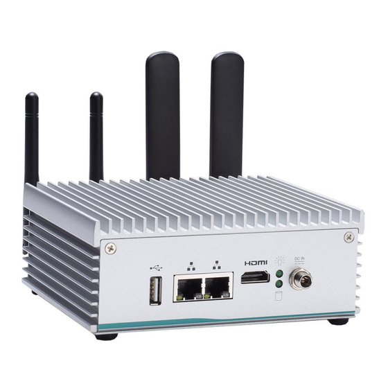
eBOX560-900-FL Series User’s Manual I/O Outlets The following figures show you I/O outlets on front view of the eBOX560-900-FL. Front View drawing Rear View drawing Introduction... -
Page 17: Packing List
Fanless Embedded System with NVIDIA® JETSON™ TX2, eBOX560-900-FL-EU 1 HDMI 2.0, 2 GbE LANs, 1 USB 2.0, 12V/60W power adapter and EU power cord If you cannot find this package or any items are missing, please contact Axiomtek distributors immediately. Introduction... - Page 18 eBOX560-900-FL Series User’s Manual This page is intentionally left blank. Introduction...
-
Page 19: Chapter 2 Hardware Installation
eBOX560-900-FL Series User’s Manual CHAPTER 2 HARDWARE INSTALLATION The eBOX560-900-FL is convenient for your various hardware configurations, such as SSD (Solid State Drive) and PCI Express Mini Card modules. The chapter 2 will show you how to install the hardware. Installing the PCI Express Mini Card Step 1 Turn off the system, and unplug the power adaptor. - Page 20 eBOX560-900-FL Series User’s Manual Step 3 Remove the bottom cover. Step 4 Locate the PCI Express mini card slot on the board. Hardware Installation...
- Page 21 eBOX560-900-FL Series User’s Manual Step 5 Holding the PCI Express mini card at a 45 degree angle up from horizontal, slowly insert the golden fingers into the PCI Express slot until it is fully inserted in. Step 6 Press it down gently, but firmly, and then secure the PCI Express mini card to the carrier by tightening up the one M2*5L Phillips pan head screw to the marked position.
-
Page 22: Installing Lte Antenna Cable
eBOX560-900-FL Series User’s Manual Installing LTE Antenna Cable Step 1 Take the Antenna kit out of its box. And turn off the system, and unplug the power adaptor. Step 2 Turn the system upside down to locate screws at the bottom side as red marked and loosen four screws. - Page 23 eBOX560-900-FL Series User’s Manual Step 4 Remove the Hex nut and washer from the Antenna cable. Step 5 Install the antenna cable connector through the opening at the back of the chassis. Hardware Installation...
- Page 24 eBOX560-900-FL Series User’s Manual Step 6 Put the washer and Hex nut into the antenna cable connector, and tighten it up. Hardware Installation...
- Page 25 eBOX560-900-FL Series User’s Manual Step 7 Connect the antenna cable to the PCI Express mini card. Hardware Installation...
-
Page 26: Installing The M.2 2280 M-Key Ssd Module
eBOX560-900-FL Series User’s Manual Installing the M.2 2280 M-Key SSD Module Step 1 Turn off the system, and unplug the power adaptor. Step 2 Turn the system upside down to locate screws at the bottom side as red marked and loosen four screws. Step 3 Remove the bottom cover. - Page 27 eBOX560-900-FL Series User’s Manual Step 4 Locate the M.2 2280 M-Key slot on the board. Step 5 Holding the M.2 2280 M-Key SSD card at a 30 degree angle up from horizontal, slowly insert the golden fingers into the M.2 2280 M-Key slot until it is fully inserted in.
- Page 28 eBOX560-900-FL Series User’s Manual Step 6 Press it down gently, but firmly, and then secure the M.2 2280 M-Key SSD card to the carrier by tightening up the one M3*4L Phillips flat head screw to the marked position. Hardware Installation...
-
Page 29: Chapter 3 Jumper Setting & Connector
eBOX560-900-FL Series User’s Manual CHAPTER 3 JUMPER SETTING & CONNECTOR Proper jumper settings configure the eBOX560-900-FL to meet your application purpose. We are here with listing a summary table of all jumpers and default settings for onboard devices, respectively. Jumper & Connector Location SBC87900 Top View Jumper setting &... - Page 30 Series User’s Manual SBC87900 Bottom View SBC87900 Rear View Note: We strongly recommended that you should not modify any unmentioned jumper setting without Axiomtek FAE’s instruction. Any modification without instruction might cause system to become damage. Jumper setting & connector...
-
Page 31: Jumper Setting Summary
eBOX560-900-FL Series User’s Manual Jumper Setting Summary Proper jumper settings configure the eBOX560-900-FL to meet your application purpose. We are herewith listing a summary table of all jumpers and default settings for onboard devices, respectively. SBC87900: Jumper & Descriptions Settings Switch Sleep 1-2 Close... -
Page 32: Other Settings (Jp2)
eBOX560-900-FL Series User’s Manual 3.2.1 Other Settings (JP2) The JP2 allows you to select the power mode as following table. Description Sleep Pin1-Pin2 Short: Sleep Pin1-Pin2 Open: Normal Operation (Default) Force Recovery Pin3-Pin4 Short: Force Recovery Pin3-Pin4 Open: Normal Operation (Default) Auto Power On Pin5-Pin6 Short: Auto Power on (Default) Pin5-Pin6 Open: Power on by power button... -
Page 33: 2280 M-Key Nvme Ssd (Cn1)
eBOX560-900-FL Series User’s Manual 3.3.1 M.2 2280 M-Key NVMe SSD (CN1) The eBOX560-900-FL comes with one M.2 2280 M-Key NVM Express SSD for storage. Signal Signal +3.3V +3.3V PERn3 PERp3 DAS/DSS# PETn3 +3.3V PETp3 +3.3V +3.3V PERn2 +3.3V PERp2 PETn2 PETp2 PERn1 PERp1... -
Page 34: Sim Card Slot (Cn3)
eBOX560-900-FL Series User’s Manual Signal Signal Connector Key Connector Key SUSCLK PEDET +3.3V +3.3V +3.3V 3.3.2 SIM Card Slot (CN3) The eBOX560-900-FL includes one SIM slot on the bottom side of the system for inserting SIM Card. It is mainly used in 3G/LTE wireless network application on CN3. Signal Jumper setting &... -
Page 35: Pci-Express Mini Card Connector (Cn4)
eBOX560-900-FL Series User’s Manual 3.3.3 PCI-Express Mini Card Connector (CN4) The eBOX560-900-FL supports a full-size PCI-Express Mini Card slots. CN4 is applying to either PCI-Express or USB 2.0 signal, and complies with PCI-Express Mini Card Spec. V1.2. PCIe signals can be selected by JP3. Please refer to Jumper Setting section. Signal Signal +3.3VSB... -
Page 36: Micro Usb 2.0 On-The-Go Connector (Cn7)
eBOX560-900-FL Series User’s Manual 3.3.4 Micro USB 2.0 On-The-Go Connector (CN7) USB On-The-Go, often abbreviated USB OTG, is a specification that allows USB devices such as digital audio players or mobile phones to act as a host, allowing other USB devices like a USB flash drive, mouse, or keyboard to be attached to them. -
Page 37: Usb2.0 Connector (Cn9)
eBOX560-900-FL Series User’s Manual 3.3.6 USB2.0 Connector (CN9) The Universal Serial Bus connectors are compliant with USB 2.0 (480Mbps), and ideally for installing USB peripherals such as keyboard, mouse, scanner, etc. Signal USB_PW R3 USB_PN6 USB_PP6 3.3.7 DC Power Jack w/ Screw (CN11) The CN11 is a DC jack with screw. -
Page 38: Digital I/O Connector (Cn14)
eBOX560-900-FL Series User’s Manual 3.3.9 Digital I/O Connector (CN14) The eBOX560-900-FL supports one 8-Channel digital I/O connector by option. The digital I/O is controlled via software programming. Signal Signal DIO01 DIO08 DIO02 DIO07 DIO03 DIO06 DIO04 DIO05 3.2.10 Debug Port Connector (JP1) The JP1 is UART interface (UART Port0) for debug port when developing software.
Need help?
Do you have a question about the eBOX560-900-FL-US and is the answer not in the manual?
Questions and answers