Table of Contents
Advertisement
Quick Links
Advertisement
Table of Contents

Related Manuals for AXIOMTEK ICO520 Series


Summary of Contents for AXIOMTEK ICO520 Series
- Page 1 ICO520 Series Din-rail Fanless Embedded System User’s Manual...
-
Page 2: Disclaimers
Axiomtek does not make any commitment to update the information in this manual. Axiomtek reserves the right to change or revise this document and/or product at any time without notice. -
Page 3: Safety Precautions
Safety Precautions Before getting started, please read the following important safety precautions. The ICO520 does not come equipped with an operating system. An operating system must be loaded first before installing any software into the computer. Be sure to ground yourself to prevent static charge when installing the internal components. -
Page 4: Classification
Classification Degree of production against electric shock: not classified Degree of protection against the ingress of water: IP20 Equipment not suitable for use in the presence of a flammable anesthetic mixture with air or with oxygen or nitrous oxide. Mode of operation: Continuous Type of protection against electric shock: Class I equipment General Cleaning Tips You may need the following precautions before you begin to clean the computer . - Page 5 Cleaning Tools Although many companies have created products to help improve the process of cleaning your computer and peripherals users can also use household items to clean their computers and peripherals. Below is a listing of items you may need or want to use while cleaning your computer or computer peripherals.
-
Page 6: Scrap Computer Recycling
Trademarks Acknowledgments Axiomtek is a trademark of Axiomtek Co., Ltd. IBM, PC/AT, PS/2, VGA are trademarks of International Business Machines Corporation. ®... -
Page 7: Table Of Contents
Table of Contents Disclaimers ......................ii Safety Precautions ....................iii Classification ......................iv General Cleaning Tips ..................iv Scrap Computer Recycling ................... vi SECTION 1 INTRODUCTION ................. 1 General Description ................1 System Specifications ............... 3 1.2.1 CPU ........................3 1.2.2 BIOS ........................ - Page 8 About Watchdog Timer ................... 69 How to Use Watchdog Timer ................69 APPENDIX B POWER BUTTON SETTING FOR WINDOWS ...... 71 APPENDIX C DIGITAL I/O ................75 viii...
-
Page 9: Section 1 Introduction
ICO520 Series User’s Manual SECTION 1 INTRODUCTION This chapter contains general information and detailed specifications of the ICO520. The Chapter 1 includes the following sections: ◼ General Description ◼ System Specification ◼ Dimensions ◼ I/O Outlets General Description The fanless embedded system ICO520 is an industrial-grade gateway with a robust hardware design, an ideal solution for communications control and protocol converter applications in harsh environments. - Page 10 ICO520 Series User’s Manual Type) ⚫ Features(Fully ◼ Fanless design ◼ Wide temperature operation: ▪ with i7-1265UE and i5-1245UE: -40°C ~ +50°C with i3-1215UE and Celeron 7305E: -40°C ~ +60°C ▪ ◼ Supports 4 RJ-45 2.5Gb Ethernet ports ◼ Supports dual display, 2 HDMI ports ◼...
-
Page 11: System Specifications
ICO520 Series User’s Manual ⚫ Embedded O.S. Supported ® ◼ Windows 10/11 64bit ◼ Linux 64bit System Specifications 1.2.1 ™ ® ⚫ Onboard Intel Core i7-1265UE processor (1.7GHz, 10-core) ™ ® ⚫ Onboard Intel Core i5-1245UE processor (1.5GHz, 10-core) ™... -
Page 12: Ethernet Ports
ICO520 Series User’s Manual 1.2.5 Ethernet Ports ⚫ LAN Chip: Intel Ethernet Controller I226IT. ⚫ The board has dual RJ-45 connectors, supporting 10/100/1000/2500 Base-T with 1.5KV magnetic isolated protection. Pin Description 10/100Base-T 1000/2500Base-T Transmit Data+ or Bidirectional BI_DA+ Transmit Data- or Bidirectional... -
Page 13: Wireless
ICO520 Series User’s Manual 1.2.7 Wireless ⚫ 1 x Full-size Rev.1.2 PCI Express Mini Card slot: PCIe/USB (for LTE/Wi-Fi) (Socket CN10). ⚫ 1 x Full-size Rev.1.2 PCI Express Mini Card slot: USB/SATA (for Wi-Fi/mSATA) (Socket CN11). Full-size Mini Card Pin Signal... - Page 14 ICO520 Series User’s Manual ⚫ 1x M.2 Key B 3050/3052 slot: PCIe/USB (for 5G/Wi-Fi) (Socket CN1) M.2 Key B Pin Signal Pin Signal N.C. +3.3VSB +3.3VSB +1.8VSB USB2_DP +1.8VSB USB2_DN N.C. +1.8VSB N.C. N.C. N.C. N.C. N.C. +1.8VSB N.C. USB3_RX_DN...
-
Page 15: Com Port: (Optional, Only For Fully Type)
ICO520 Series User’s Manual ⚫ 3 x SIM slot (1 for M.2 on CN4; 2 for full-size PCI Express Mini Card on CN9 and CN13) ⚫ 5 x Antenna holes Pin Signal SIM_PWR SIM_RESET SIM_CLK SIM_VPP SIM_DATA 1.2.8 COM Port: (optional, only for Fully Type) ⚫... -
Page 16: Dio: (Optional, Only For Fully Type)
ICO520 Series User’s Manual 1.2.9 DIO: (optional, only for Fully Type) ⚫ 8bit DI and 8bit DO with 2KV optical isolation Digital Input Input Channels 8 source type Input Voltage 0 to 30VDC Input Digital Input Levels for Logic level 0: Close to GND. -
Page 17: Led
ICO520 Series User’s Manual External PWR DI 8 DI 9 DI 10 DI 11 DIO_GND External PWR DI 12 DI 13 10 DI 14 11 DI 15 12 DIO_GND ⚫ COM+ DO 0 DO 1 DO 2 DO 3 COM-... -
Page 18: Power& Reset Button
ICO520 Series User’s Manual 1.2.11 Power& Reset Button ⚫ AT auto power on ⚫ Reset Button. Pin Description Reset Button Note: Refer to APPENDIX B for instructions on Power button settings for Windows. 1.2.12 Power ⚫ Wide-range 12 - 48V DC power input with terminal block. -
Page 19: Dimensions
ICO520 Series User’s Manual 1.2.19 Dimensions 82mm(3.42”) (W) x135mm(5.31”) (D) x155mm(6.1”) (H) ⚫ 1.2.20 System I/O Outlets ⚫ Two HDMI connector display. ⚫ Four 10/100/1000/2500 base-T RJ-45 connectors with 1.5KV magnetic isolated protection. ⚫ Four USB 3.1 connectors. ⚫ Two 2x6-pin terminal block connectors for DIO. -
Page 20: System Power Consumption
ICO520 Series User’s Manual 1.2.22 System Power consumption ⚫ 12-48VDC, 4.01-1.01A Introduction... -
Page 21: System Block Diagram
ICO520 Series User’s Manual 1.2.23 System Block diagram Introduction... -
Page 22: Placement
ICO520 Series User’s Manual Placement 1.2.24 PSB519 TOP View PSB519 Buttom View Introduction... - Page 23 ICO520 Series User’s Manual MIO105 TOP View MIO105 Buttom View Introduction...
-
Page 24: Connectors
ICO520 Series User’s Manual Connectors 1.2.25 Signals go to other parts of the system through connectors. Loose or improper connection might cause problems, please make sure all connectors are properly and firmly connected. Here is a summary table which shows all connectors on the hardware. -
Page 25: Dimensions
ICO520 Series User’s Manual Dimensions The following diagrams show you the dimensions and outlines of the ICO520. Fully Type Introduction... - Page 26 ICO520 Series User’s Manual Simplified Type Introduction...
-
Page 27: I/O Outlets
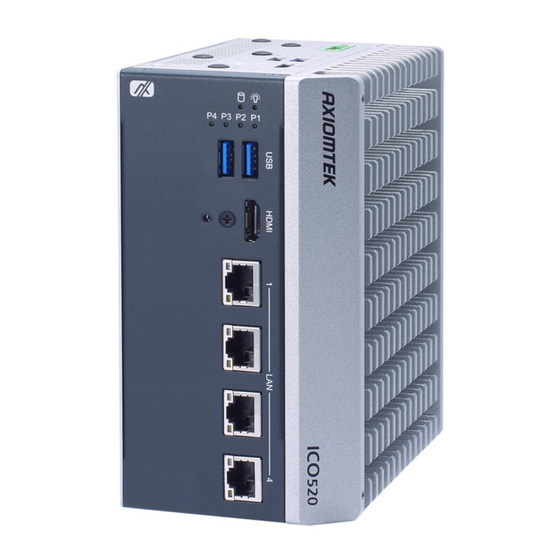
ICO520 Series User’s Manual I/O Outlets The following figures show you I/O outlets on the front view, top view and bottom view of the ICO520. Type Fully Simplified Front Introduction... - Page 28 ICO520 Series User’s Manual Right Left Bottom Introduction...
-
Page 29: Section 2 Hardware Installation
ICO520 Series User’s Manual SECTION 2 HARDWARE INSTALLATION The ICO520 is flexible for your different hardware configurations, such as the memory module, hard disk drive, mini card and I/O module. Chapter 2 will show you how to install the hardware. - Page 30 ICO520 Series User’s Manual Hardware Installation...
- Page 31 ICO520 Series User’s Manual Step 3 Put the thermal pad on the SO-DIMM socket. Then insert the module’s gold finger into the socket and push the module down to finish the memory installation. a. Paste Sponge b. Install Memory c. Install thermal pads and sheets...
- Page 32 ICO520 Series User’s Manual d. Tighten the screw Step 4 Insert the PCIe/USB Card into the socket and fasten screws. (Note: For the mini card with SIM function, the PCIe card should be inserted into (Socket10、11) Hardware Installation...
- Page 33 ICO520 Series User’s Manual Put the cover back onto the system, and fasten all screws tightly to close the chassis. Hardware Installation...
- Page 34 ICO520 Series User’s Manual Step 5 Insert the M.2 Key B 3050/3052 slot: PCIe/USB (for 5G/Wi-Fi) (Socket CN1) Hardware Installation...
- Page 35 ICO520 Series User’s Manual Put the cover back onto the system, and fasten all screws tightly to close the chassis. Hardware Installation...
-
Page 36: Installing The Hard Disk、Nvme Drive
ICO520 Series User’s Manual Installing the Hard Disk、NVMe Drive Step 1 Turn off the system. Step 2 Loosen the screw as shown below, and pull out the SSD、NVMe tray from the system. Fully Type Simplified Type Hardware Installation... - Page 37 ICO520 Series User’s Manual a. SSD Fully Type Simplified Type Hardware Installation...
- Page 38 ICO520 Series User’s Manual b. NMVe For Fully Type/ Simplified Type Step 3 Fasten the SSD screws (marked by the red arrows below) to fix the SSD. Then screw the SSD install the tray back to the system. Hardware Installation...
- Page 39 ICO520 Series User’s Manual Hardware Installation...
- Page 40 ICO520 Series User’s Manual Step 4 Fasten the NVMe(M.2 Key B 3050/3052) screws (marked by the red arrows below) to fix the NVMe(M.2 Key B 3050/3052). Then screw the NVMe(M.2 Key B 3050/3052) install the tray back to the system.
-
Page 41: Installing The Din-Rail Mounting Kit
ICO520 Series User’s Manual Installing the DIN-rail Mounting Kit Step 1 Prepare the DIN-rail Mount assembly components (screws and bracket) ready. Step 2 Assemble the bracket to the system and fasten screws tight. Hardware Installation... - Page 42 ICO520 Series User’s Manual This page is intentionally left blank. Hardware Installation...
-
Page 43: Chapter 3 Ami Uefi Bios Utility
ICO520 Series User’s Manual CHAPTER 3 AMI UEFI BIOS UTILITY The AMI UEFI BIOS provides users with a built-in Setup program to modify basic system configuration. All configured parameters are stored in a flash-backed-up to save the Setup information whenever the power is turned off... -
Page 44: The Main Menu
ICO520 Series User’s Manual The Main Menu Once you enter the AMI BIOS Aptio Setup Utility, the Main Menu appears on the screen. In the Main Menu, there are several Setup functions and a couple of Exit options for your selection. -
Page 45: Advanced Features
ICO520 Series User’s Manual Advanced Features The Advanced menu also allows users to set configuration of the CPU and other system devices. Users can select any items in the left frame of the screen to go to sub menus: ►... - Page 46 ICO520 Series User’s Manual ⚫ Hardware Monitor This screen displays the temperature of CPU and system, as well as system voltages (+3.3V, +12V and +5V ,etc). AMI UEFI BIOS Utility...
- Page 47 ICO520 Series User’s Manual ⚫ Trusted Computing In terms of Trusted Platform Module Device, users can choose between disabling TPM and enabling Platform Trust Technology. Security Device Support Enable or disable BIOS support for security device, see image below. OS will not show security device.
- Page 48 ICO520 Series User’s Manual ⚫ CPU Configuration This screen shows the CPU version and its detailed information. AMI UEFI BIOS Utility...
- Page 49 ICO520 Series User’s Manual ⚫ Storage Configuration AMI UEFI BIOS Utility...
- Page 50 ICO520 Series User’s Manual ⚫ SATA Configuration Serial ATA Port 0~1 It shows the device installed in connector SATA0~1. AMI UEFI BIOS Utility...
- Page 51 ICO520 Series User’s Manual ⚫ NVMe Configuration AMI UEFI BIOS Utility...
- Page 52 ICO520 Series User’s Manual USB Configuration USB Configuration USB Devices Display all detected USB devices. AMI UEFI BIOS Utility...
- Page 53 ICO520 Series User’s Manual ⚫ Device Configuration Device configuration divides into two parts: one part is onboard device; the other is module device. The Module Device Configuration menu would dynamically appear when a module device is plugged into the slot. When no module is plugged in, the screen would only show Onboard Device Configuration.
- Page 54 ICO520 Series User’s Manual ⚫ Module COM port Configuration When the module have COM port functions, the module COM configuration menu would show. The default setting for all Serial Ports is RS232. You can change the setting by selecting the value you want in each COM port type. The system supports RS422 &...
- Page 55 ICO520 Series User’s Manual AMI UEFI BIOS Utility...
- Page 56 ICO520 Series User’s Manual AMI UEFI BIOS Utility...
- Page 57 ICO520 Series User’s Manual AMI UEFI BIOS Utility...
- Page 58 ICO520 Series User’s Manual AMI UEFI BIOS Utility...
- Page 59 ICO520 Series User’s Manual AMI UEFI BIOS Utility...
- Page 60 ICO520 Series User’s Manual AMI UEFI BIOS Utility...
- Page 61 ICO520 Series User’s Manual AMI UEFI BIOS Utility...
- Page 62 ICO520 Series User’s Manual AMI UEFI BIOS Utility...
- Page 63 ICO520 Series User’s Manual AMI UEFI BIOS Utility...
-
Page 64: Chipset Feature
ICO520 Series User’s Manual Chipset Feature The Chipset menu allows users to change the advanced chipset settings. Users can select any of the items in the left frame of the screen to go to the sub menus: System Agent (SA) Configuration... -
Page 65: Security
ICO520 Series User’s Manual Security The Security menu allows users to set an administrator password and a user password to enhance system security. No password is set in the default setting. (Please refer below graphics.) Administrator Password This item indicates whether an administrator password has been set (installed or uninstalled). - Page 66 ICO520 Series User’s Manual ⚫ Secure Boot Secure Boot Secure Boot feature is Active if Secure Boot is Enabled, Platform Key (PK) is enrolled and the System is in User mode. The mode change requires platform reset. Secure Boot ensures that the system only boots from trusted software, preventing malicious software from loading and compromising the device.
- Page 67 ICO520 Series User’s Manual Secure Boot Mode Secure Boot mode options: Standard or Custom. In Custom mode, Secure Boot Policy variables can be configured by a physically present user without full authentication. AMI UEFI BIOS Utility...
- Page 68 ICO520 Series User’s Manual AMI UEFI BIOS Utility...
- Page 69 ICO520 Series User’s Manual AMI UEFI BIOS Utility...
- Page 70 ICO520 Series User’s Manual AMI UEFI BIOS Utility...
- Page 71 ICO520 Series User’s Manual AMI UEFI BIOS Utility...
- Page 72 ICO520 Series User’s Manual The Factory Key Provision The Factory Key Provision ensures that the device has secure access to encrypted resources, such as data storage or communication. The keys are often unique to each device and can be used to secure firmware updates, secure boot processes, and to encrypt data at rest. The factory key provisioning process is an important step in securing devices and maintaining the confidentiality of sensitive information.
-
Page 73: Boot Type
ICO520 Series User’s Manual Boot Type The Boot menu allows users to change boot options of the system. AMI UEFI BIOS Utility... - Page 74 ICO520 Series User’s Manual Setup Prompt Timeout Use this item to set up number of seconds to wait for setup activation key where 65535(0xFFFF) means indefinite waiting. Bootup NumLock State Use this item to select the power-on state for the keyboard NumLock.
-
Page 75: Save & Exit
ICO520 Series User’s Manual Save & Exit The Save & Exit menu allows users to load system configurations with optimal or fail-safe default values. Save Changes and Exit When users have completed the system configuration changes, select this option to leave Setup and return to Main Menu. - Page 76 ICO520 Series User’s Manual Save Changes After completing the system configuration changes, select this option to save changes. Select Save Changes from the Save & Exit menu and press <Enter>. Select Yes to save changes. Discard Changes Select this option to quit Setup without making any permanent changes to the system configurations.
-
Page 77: Appendix Awatchdog Timer
ICO520 Series User’s Manual APPENDIX A WATCHDOG TIMER About Watchdog Timer After the system stops working for a while, it can be auto-reset by the watchdog timer. The integrated watchdog timer can be set up in the system reset mode by a program. - Page 78 ICO520 Series User’s Manual This page is intentionally left blank. Watchdog Timer...
-
Page 79: Appendix Bpower Button Setting For Windows
ICO520 Series User’s Manual APPENDIX B POWER BUTTON SETTING FOR WINDOWS To change how the power button operates, go to the console of the PC and then follow below figures to complete the setting. Power Button Setting For Windows... - Page 80 ICO520 Series User’s Manual Power Button Setting For Windows...
- Page 81 ICO520 Series User’s Manual Power Button Setting For Windows...
- Page 82 ICO520 Series User’s Manual This page is intentionally left blank. Power Button Setting For Windows...
-
Page 83: Appendix Cdigital I/O
ICO520 Series User’s Manual APPENDIX C DIGITAL I/O Digital Input: Ext Power Input Voltage: 30Vdc Max. Digital Input channels: 4, sink/source type Digital Input voltage: 0 to 30VDC Input level for dry contacts: Logic level 0: close Logic level 1: open Input level for wet contacts: Logic level 1: +/-3VDC max. - Page 84 ICO520 Series User’s Manual Digital Input Wiring Dry Contact (1): With external power. Dry Contact (2): Without external power. Digital I/O...
- Page 85 ICO520 Series User’s Manual Wet Contact (1): Wet Contact (2): Digital Output Wiring DO drive high: x_OUT equal to COM-(up to 200mA) DO drive low: High impedance Digital I/O...
Need help?
Do you have a question about the ICO520 Series and is the answer not in the manual?
Questions and answers