Table of Contents
Advertisement
Quick Links
Advertisement
Table of Contents

Related Manuals for AXIOMTEK eBOX635-881-FL-i7-4770TE


Summary of Contents for AXIOMTEK eBOX635-881-FL-i7-4770TE
- Page 1 eBOX635-881-FL Series Embedded System User’s Manual...
- Page 2 Axiomtek does not make any commitment to update the information in this manual. Axiomtek reserves the right to change or revise this document and/or product at any time without notice No part of this document may be reproduced, stored in a retrieval system, or transmitted, in any form or by any means, electronic, mechanical, photocopying, recording, or otherwise, without the prior written permission of Axiomtek Co., Ltd.
-
Page 3: Safety Precautions
Safety Precautions Before getting started, please read the following important safety precautions. The eBOX635-881-FL does not come equipped with an operating system. An operating system must be loaded first before installing any software into the computer. Be sure to ground yourself to prevent static charge when installing the internal components. -
Page 4: General Cleaning Tips
General Cleaning Tips You may need the following precautions before you begin to clean the computer. When you clean any single part or component for the computer, please read and understand the details below fully. When you need to clean the device, please rub it with a piece of dry cloth. Be cautious of the tiny removable components when you use a vacuum cleaner to absorb the dirt on the floor. -
Page 5: Scrap Computer Recycling
If the computer equipments need the maintenance or are beyond repair, we strongly recommended that you should inform your Axiomtek distributor as soon as possible for the suitable solution. For the computers that are no longer useful or no longer working well, please contact your Axiomtek distributor for recycling and we will make the proper arrangement. -
Page 6: Table Of Contents
Table of Contents Disclaimers ......................ii Safety Precautions ....................iii Classification ......................iii General Cleaning Tips ................... iv Scrap Computer Recycling ..................v CHAPTER 1 INTRODUCTION ................ 1 General Description ................2 System Specifications ................ 3 1.2.1 CPU ........................3 1.2.2 I/O System ...................... - Page 7 3.2.17 Serial ATA Connectors (SATA1-SATA2) ............30 3.2.18 SIM Card Slots (SCN19).................. 30 3.2.19 CFast™ Socket ....................31 3.2.20 Half-Size Express Mini Card Slot (SCN13) ........... 32 3.2.21 Full-Size Express Mini Card (w/ SIM Slot)/ mSATA (SCN14) ...... 33 3.2.22 Power Output Connector (SCN22, SCN26) ........... 34 CHAPTER 4 AMI BIOS SETUP UTILITY ............
- Page 8 This page is intentionally left blank. viii...
-
Page 9: Chapter 1 Introduction
eBOX635-881-FL Series User’s Manual CHAPTER 1 INTRODUCTION This chapter contains general information and detailed specifications of the eBOX635-881-FL. The Chapter 1 includes the following sections: General Description System Specifications Dimensions I/O Outlets Packing List Model List Introduction... -
Page 10: General Description
eBOX635-881-FL Series User’s Manual General Description The eBOX635-881-FL is an embedded system that supports LGA1150 Socket 4 generation Intel® Core™ i7/i5/i3/Celeron processor to support W indows 7, W indows 7 Embedded, W indows 8, W indows 8 Embedded W indows 10 or Linux, suitable for the most endurable operation. -
Page 11: System Specifications
eBOX635-881-FL Series User’s Manual System Specifications 1.2.1 CPU LGA1150 Socket Intel® Core™ i7/i5/i3/Celeron processor W orking temperature depends on TDP of processor, please refer to 1.2.3 System Specification Chipset Intel® Haswell H81 chipset BIOS ... -
Page 12: Driver Cd Content
eBOX635-881-FL Series User’s Manual Vibration Endurance 3Grm w/ CFast™ (5-500Hz, X, Y, Z directions) Weight 2.5 kg (5.51 lb) without package 4.5 kg (9.92 lb) with package Dimensions 280mm(11.02”) (W) x150mm(5.91”) (D) x 76mm(2.99”) (H) 1.2.4 Driver CD Content ... -
Page 13: Dimensions
eBOX635-881-FL Series User’s Manual Dimensions The following diagrams show you dimensions and outlines of the eBOX635-881-FL. 1.3.1 System Dimension Introduction... -
Page 14: Wall Mount Dimension
eBOX635-881-FL Series User’s Manual 1.3.2 Wall mount Dimension Introduction... -
Page 15: I/O Outlets
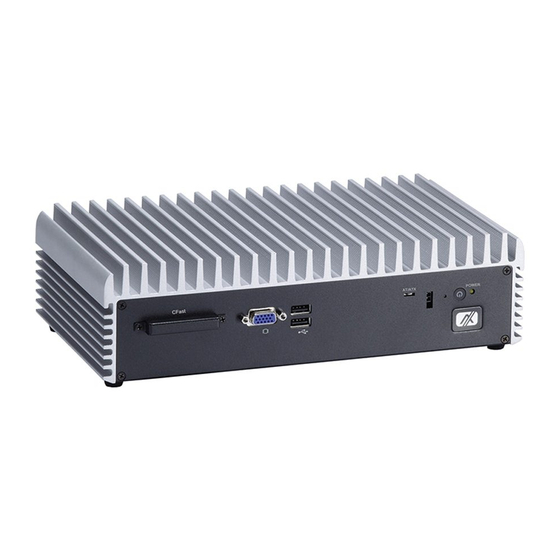
eBOX635-881-FL Series User’s Manual I/O Outlets The following figures show you I/O outlets on front view of the eBOX635-881-FL. Front View drawing Power Button Remote Switch AT/ATX Switch Reset ™ CFast slot USB 2.0 Indicator HDD State Note: If you set AT/ATX switch to AT mode, the system will be automatically power on without pressing soft power button during power input. -
Page 16: Packing List
Optional Antenna Optional Mini Card Module Optional 2.5” SATA Storage Optional CFast™ Card Optional Power Cord Note: If you can not find this package or any items are missing, please contact Axiomtek distributors immediately. Introduction... -
Page 17: Model List
Fanless Embedded System with Intel Pentium G3320TE (2 Cores) 2.3G Processor, HDMIx2/VGA, DisplayPort, GbE LAN*2, eBOX635-881-FL-G3320TE 19/12V AC/DC USB3.0*2, Audio, RS-232/422/485*6, DI*8/DO*8, Power Adapter If you cannot find this package or any items are missing, please contact Axiomtek distributors immediately. Introduction... - Page 18 eBOX635-881-FL Series User’s Manual This page is intentionally left blank. Introduction...
-
Page 19: Chapter 2 Hardware Installation
eBOX635-881-FL Series User’s Manual CHAPTER 2 HARDWARE INSTALLATION The eBOX635-881-FL is convenient for your various hardware configurations, such as HDD (Hard Disk Drive), SSD (Solid State Drive) CFast™ card or PCI Express Mini Card modules. The chapter 2 will show you how to install the hardware. Installing the 2.5”... -
Page 20: Installing The Memory Module
eBOX635-881-FL Series User’s Manual Step 5 Please refer to the following photo to connect SATA power and signal cables. Step 6 Fasten screws of HDD drive bay. Installing the Memory Module Step 1 Turn off the system, and unplug the power cord. Step 2 Turn the system upside down to locate screws at the Bottom, loosen screws. - Page 21 eBOX635-881-FL Series User’s Manual Step 4 You will see the DRAM slot under bracket Step 5 Take out the thermal pad from accessory kit Step 6 Remove transparent plastic Mylar from thermal pad, and stick the thermal pad onto motherboard. Hardware Installation...
- Page 22 eBOX635-881-FL Series User’s Manual Step 7 Locate the memory module, insert the gold colored contact into the socket, and push the module down, until it is firmly seated by locking two latches on the sides. Step 8 Take 2 thermal pad, remove the transparent plastic mylar and stick it onto memory.
- Page 23 eBOX635-881-FL Series User’s Manual Step 10 Assembly the Top Cover back and fasten all screws. Hardware Installation...
-
Page 24: Installing The Cfast
eBOX635-881-FL Series User’s Manual Installing the CFast™ Step 1 Turn off the system, and unplug the power cord. Step 2 Turn the system to the side with CFast™ cover. Step 3 Loosen screws to remove the CFast™ cover. Step 4 Slide CFast™ card into CFast™ slot with caution. Step 5 Close the cover to the chassis, and fasten all screws. -
Page 25: Installing The Express Mini Card
eBOX635-881-FL Series User’s Manual Installing the Express Mini Card Step 1 Turn off the system, and unplug the power cord. Step 2 Turn the system upside down to locate screws at the Bottom, loosen screws. Step 3 Remove the bottom cover to locate the Express Mini Card slot. Hardware Installation... - Page 26 eBOX635-881-FL Series User’s Manual Step 4 Slide Mini Card into Mini Card slot with caution, and fasten screw of express Mini Card. Full Size Mini Card Half Size Mini Card Step 5 Assembly the Top Cover back and fasten all screws. Hardware Installation...
-
Page 27: Installing Cpu And Pch Thermal Pad
We have installed thermal pad for eBOX635-881-FL already and this chapter just to let you know how to replace new thermal pad by yourself. If any further information is requested, please feel free to contact Axiomtek distributors or FAE immediately. - Page 28 eBOX635-881-FL Series User’s Manual This page is intentionally left blank. Hardware Installation...
-
Page 29: Chapter 3 Jumper Setting & Connectors
eBOX635-881-FL Series User’s Manual CHAPTER 3 JUMPER SETTING & CONNECTORS Proper jumper settings configure the eBOX635-881-FL to meet your application purpose. We are herewith listing a summary table of all jumpers and default settings for onboard devices, respectively. SBC Placement SBC87881 Top Side Jumper Setting &... - Page 30 Series User’s Manual SBC87881 Bottom Side Note: We strongly recommended that you should not modify any unmentioned jumper setting without Axiomtek FAE’s instruction. Any modification without instruction might cause system to become damage. Jumper Setting & Connector...
-
Page 31: Jumper Settings And Connectors
eBOX635-881-FL Series User’s Manual Jumper Settings and Connectors Connectors connect the system with other parts/devices. Loose or improper connection might cause problems. Make sure all connectors are properly and firmly connected. Below summary table shows you all connectors on the eBOX635-881-FL. Jumper &... -
Page 32: Cmos Clear Jumper (Sjp2 On Sbc87881)
eBOX635-881-FL Series User’s Manual 3.2.1 CMOS Clear Jumper (SJP2 on SBC87881) Function Setting Normal (Default) Clear RTC 3.2.2 DC Power In Connector (SCN1) The system supports a DC 19V power-din connector for system power input. Signal DC 19V DC 19V 3.2.3 Digital Input Connector The system is equipped with an 8-channel digital Input connector that meets... -
Page 33: Digital Output Connector
eBOX635-881-FL Series User’s Manual Dry Contact Wiring Wet Contact Wiring 3.2.4 Digital Output Connector The system is equipped with an 8-channel digital output connector that meets requirements for a system customary automation control. The digital I/O can be configured to control cash drawers and sense warning signals from an Uninterrupted Power System (UPS), or perform store security control. -
Page 34: Vga Connector
eBOX635-881-FL Series User’s Manual 3.2.5 VGA Connector The VGA connector is a slim type 15-pin D-Sub connector which is common for the CRT VGA display. The VGA interface configuration can be configured via the software utility. 3.2.6 DisplayPort Connector DisplayPort interface is also called DP port. Signal DPB_LANE0 DPB_LANE0#... -
Page 35: Hdmi Connector (Scn6-Scn7)
eBOX635-881-FL Series User’s Manual 3.2.7 HDMI Connector (SCN6-SCN7) The HDMI (High-Definition Multimedia Interface) is a compact digital interface which is capable of transmitting high-definition video and high-resolution audio over a single cable. Its interface is available through connector SCN6 or SCN7. Signal Signal HDMI OUT_DATA2+... -
Page 36: Usb 2.0 Connector (Susb1 And Susb2)
eBOX635-881-FL Series User’s Manual 3.2.9 USB 2.0 Connector (SUSB1 and SUSB2) The Universal Serial Bus connectors are compliant with USB 2.0 (480Mbps), and ideally for installing USB peripherals such as keyboard, mouse, scanner, etc. SUSB1 carries USB port 1and 2. SUSB2 carries USB port 3and 4. -
Page 37: Ethernet Connector (Lan1~Lan2)
eBOX635-881-FL Series User’s Manual 3.2.12 Ethernet Connector (LAN1~LAN2) The RJ-45 connector is for Ethernet. To connect the board to a 1000/100/10 Base-T hub, just plug one end of the cable into connector and connect the other end (phone jack) to a 1000/100/10-Base-T hub. -
Page 38: At/Atx Switch
eBOX635-881-FL Series User’s Manual 3.2.16 AT/ATX Switch If you set AT/ATX switch to AT mode, the system will be automatically power on without pressing soft power button during power input; we can use this switch to achieve auto power on demand. 3.2.17 Serial ATA Connectors (SATA1-SATA2) These Serial Advanced Technology Attachment (Serial ATA or SATA) connectors are for high-speed SATA interfaces. -
Page 39: Cfast™ Socket
eBOX635-881-FL Series User’s Manual 3.2.19 CFast™ Socket The system is equipped with a CFast™ socket on the bottom side to support a CFast™ card which is based on the Serial ATA bus. The socket is specially designed to avoid incorrect installation of the CFast™... -
Page 40: Half-Size Express Mini Card Slot (Scn13)
eBOX635-881-FL Series User’s Manual 3.2.20 Half-Size Express Mini Card Slot (SCN13) PCI Express Mini Card connector supports a PCI Express x1 link and a USB 2.0 link. A PCI Express Mini Card can be applied to either PCI Express or USB 2.0. It complies with PCI- Express Mini Card Spec. -
Page 41: Full-Size Express Mini Card (W/ Sim Slot)/ Msata (Scn14)
eBOX635-881-FL Series User’s Manual 3.2.21 Full-Size Express Mini Card (w/ SIM Slot)/ mSATA (SCN14) You may need to adjust the BIOS setting to select mSATA or Mini card PCI-E interface. This is a PCI-Express Mini Card connector which supports PCI-Express x1 link, SATA link , USB 2.0 link and 3G wireless network application(SCN19). -
Page 42: Power Output Connector (Scn22, Scn26)
eBOX635-881-FL Series User’s Manual 3.2.22 Power Output Connector (SCN22, SCN26) Signal +12V level +5V level Jumper Setting & Connector... -
Page 43: Chapter 4 Ami Bios Setup Utility
eBOX635-881-FL Series User’s Manual CHAPTER 4 AMI BIOS SETUP UTILITY The AMI BIOS provides users with a built-in setup program to modify basic system configuration. All configured parameters are stored in a battery-backed CMOS to save the setup information whenever the power is turned off. This chapter provides users with detailed description about how to set up basic system configuration through the AMI BIOS setup utility. -
Page 44: Main Menu
eBOX635-881-FL Series User’s Manual Main Menu When you first enter the setup utility, you will enter the Main setup screen. You can always return to the Main setup screen by selecting the Main tab. System Time/Date can be set up as described below. -
Page 45: Advanced Menu
eBOX635-881-FL Series User’s Manual Advanced Menu mSATA/PCIE select Use this item to select the SCN14 to mSATA or Mini-PCIE mode. Launch PXE OpROM Use this item to enable or disable the boot ROM function of the onboard LAN chip when the system boots up. - Page 46 eBOX635-881-FL Series User’s Manual ACPI Settings You can use this screen to select options for the ACPI configuration, and change the value of the selected option. A description of the selected item appears on the right side of the screen. ACPI Sleep State Allow you to select the Advanced Configuration and Power Interface (ACPI) sleep state.
- Page 47 eBOX635-881-FL Series User’s Manual CPU Configuration This screen shows the CPU Configuration, and you can change the value of the selected option. Intel Virtualization Technology Allow you to enable or disable Intel Virtualization Technology. When enabled, a VMM can utilize the additional hardware capabilities provided by Vanderpool Technology . AMI BIOS Setup Utility...
- Page 48 eBOX635-881-FL Series User’s Manual SATA Configuration In the SATA Configuration menu, you can see the currently installed hardware in the SATA ports. During system boot up, the BIOS automatically detects the presence of SATA devices. SATA Mode Selection Use this item to choose the SATA operation mode. Here are the options for your selection: IDE Mode and AHCI Mode.
- Page 49 eBOX635-881-FL Series User’s Manual PCH-FW Configuration This screen shows the ME Firmware version, and its detail information. NCT6106D Super IO Configuration You can use this screen to select options for the Super IO Configuration, and change the value of the selected option. A description of the selected item appears on the right side of the screen.
- Page 50 eBOX635-881-FL Series User’s Manual Serial Port 1 Configuration Serial Port Use this item to enable or disable serial port 1. The optimal setting for base I/O address is 3F8h and for interrupt request line is IRQ4. Change Settings Here are the options for your selection; Auto;...
- Page 51 eBOX635-881-FL Series User’s Manual Serial Port 2 Configuration Serial Port Use this item to enable or disable serial port 2. The optimal setting for base I/O address is 2F8h and for interrupt request line is IRQ3. Change Settings Here are the options for your selection; Auto;...
- Page 52 eBOX635-881-FL Series User’s Manual Serial Port 3 Configuration Serial Port Use this item to enable or disable serial port 3. The optimal setting for base I/O address is 3E8h and for interrupt request line is IRQ7. Change Settings Here are the options for your selection; Auto;...
- Page 53 eBOX635-881-FL Series User’s Manual Serial Port 4 Configuration Serial Port Use this item to enable or disable serial port 4. The optimal setting for base I/O address is 2E8h and for interrupt request line is IRQ5. Change Settings Here are the options for your selection; Auto;...
- Page 54 eBOX635-881-FL Series User’s Manual Serial Port 5 Configuration Serial Port Use this item to enable or disable serial port 5. The optimal setting for base I/O address is 2E0h and for interrupt request line is IRQ10. Change Settings Here are the options for your selection; Auto;...
- Page 55 eBOX635-881-FL Series User’s Manual Serial Port 6 Configuration Serial Port Use this item to enable or disable serial port 6. The optimal setting for base I/O address is 2F0h and for interrupt request line is IRQ6. Change Settings Here are the options for your selection; Auto;...
-
Page 56: Chipset Menu
eBOX635-881-FL Series User’s Manual Chipset Menu The Chipset menu allows users to change the advanced chipset settings. You can select any of the items in the left frame of the screen to go to the sub menus: ► PCH - IO Configuration ►... - Page 57 eBOX635-881-FL Series User’s Manual PCH - IO Configuration This screen allows users to configure PCH – IO Configuration parameters. For items marked with “”, please press <Enter> for more options. USB Configuration Use this item for further setting of USB configuration. AMI BIOS Setup Utility...
- Page 58 eBOX635-881-FL Series User’s Manual System Agent (SA) Configuration This screen allows users to configure System Agent (SA) parameters. For items marked with “”, please press <Enter> for more options. Graphics Configuration Use this item for further setting of graphics configuration. Internal Graphics You can use this item to select internal graphics to enable or disable.
- Page 59 eBOX635-881-FL Series User’s Manual Primary IGFX Boot Display Select the video device which will be activated during POST (Power-On Self Test). This has no effect if external graphics present. Memory Configuration Use this item for further setting of memory configuration, this screen displays memory information, and allows user to set memory configuration.
-
Page 60: Boot Menu
eBOX635-881-FL Series User’s Manual Boot Menu The Boot menu allows users to change boot options of the system. Setup Prompt Timeout Number of seconds to wait for setup activation key. 65535(0xFFFF) means indefinite waiting. Bootup NumLock State Use this item to select the power-on state for the NumLock. ... -
Page 61: Security Menu
eBOX635-881-FL Series User’s Manual Security Menu The Security menu allows users to change the security settings for the system. Administrator Password This item indicates whether an administrator password has been set (installed or uninstalled). User Password This item indicates whether an user password has been set (installed or uninstalled). AMI BIOS Setup Utility... -
Page 62: Save & Exit Menu
eBOX635-881-FL Series User’s Manual Save & Exit Menu The Save & Exit menu allows users to load your system configuration with optimal or fail-safe default values. Save Changes and Exit When you have completed the system configuration changes, select this option to leave Setup and return to Main Menu. - Page 63 eBOX635-881-FL Series User’s Manual Discard Changes Select this option to quit Setup without making any permanent changes to the system configuration. Select Discard Changes from the Save & Exit menu and press <Enter>. Select Yes to discard changes. Restore Defaults It automatically sets all Setup options to a complete set of default settings when you select this option.
- Page 64 eBOX635-881-FL Series User’s Manual This page is intentionally left blank. AMI BIOS Setup Utility...
-
Page 65: Appendix Watchdog Timer
eBOX635-881-FL Series User’s Manual APPENDIX WATCHDOG TIMER About Watchdog Timer Software stability is major issue in most application. Some embedded systems are not watched by human for 24 hours. It is usually too slow to wait for someone to reboot when computer hangs. -
Page 66: Assembler Sample Program
eBOX635-881-FL Series User’s Manual Assembler Sample Program Following is example to enable configuration by using debug tool. Enable WDT 1.Enable configuration -O 2E 87 -O 2E 87 2. Select Logic device: -O 2E 07 -O 2F 08 3. WDT Device Enable -O 2E 30 -O 2F 01 5.
Need help?
Do you have a question about the eBOX635-881-FL-i7-4770TE and is the answer not in the manual?
Questions and answers