
Related Manuals for WAGNER IP 5000


Summary of Contents for WAGNER IP 5000
- Page 1 Edition 08/2021 IP 5000 IP 5000-USD Fresh Powder and Transfer Pump P_04342 P_04342 II 3D Ex tc IIIB T85°C Dc...
-
Page 3: Table Of Contents
Electrical Connection Cables 4.2.6 Cleaning and Flushing 4.2.7 Maintenance and Repair 4.2.8 Protective and Monitoring Equipment DESCRIPTION Design of the IP 5000 Powder Pump 5.1.1 IP 5000 Version 5.1.2 IP 5000-USD Version Functioning Operating Elements on Control Cabinet Extent of Delivery Data 5.5.1... - Page 4 Commissioning as Transfer Pump (BigBag) 6.9.3 Pin Assignment in the Control Cabinet OPERATION Training the Operating Personnel Tasks Operating Modes Operation with WAGNER Powder Center Setting Elements in the Control Cabinet 7.5.1 DIP Switch Functions 7.5.2 A+/A- Buttons 7.5.3 Function 1 "Use of Powder Center/BigBag"...
- Page 5 IP 5000 EDITION 08/2021 ORDER NUMBER DOC241936 ACCESSORIES SPARE PARTS 12.1 How to Order Spare Parts 12.2 Powder Pump Spare Parts List 12.3 Control Cabinet Spare Parts List 12.4 Connecting Plug Spare Parts List 12.5 SN 600/14 Suction Lance Spare Parts List 12.6...
-
Page 6: About These Instructions
IP 5000 EDITION 08/2021 ORDER NUMBER DOC241936 ABOUT THESE INSTRUCTIONS PREFACE The operating manual contains information about safely operating, maintaining, cleaning and repairing the device. The operating manual is part of the device and must be available to the operating and service personnel. -
Page 7: Languages
IP 5000 EDITION 08/2021 ORDER NUMBER DOC241936 LANGUAGES The operating manual is available in the following languages: Original operating manual Language Order no. German 241935 Translation of the original operating manual Language Order no. Language Order no. English 241936 Danish... -
Page 8: Terminology For The Purpose Of This Manual
IP 5000 EDITION 08/2021 ORDER NUMBER DOC241936 TERMINOLOGY FOR THE PURPOSE OF THIS MANUAL Cleaning Cleaning Manual cleaning of devices and device parts with cleaning agent Flushing Internal flushing of paint-wetted parts with compressed air Personnel qualifications Trained person Is instructed in the tasks assigned to him/her, the potential risks associated with improper behavior as well as the necessary protective devices and measures. -
Page 9: Using In Accordance With The Instructions
DEVICE TYPE Pneumatic feed pump for feeding powder lacquers. TYPE OF USE The IP 5000 powder pump is used to feed powder coating products from different container types. Application areas: The IP 5000 powder pump is used to feed powder lacquers –... -
Page 10: Identification
Temperature class: maximum surface temperature < 85 °C; 185 °F High safety level PERMISSIBLE DEVICE COMBINATIONS The IP 5000 powder pump can be used in the following WAGNER powder centers: – PZ 2008 powder center – SuperCenter 2012 – PXM powder center –... -
Page 11: Basic Safety Instructions
IP 5000 EDITION 08/2021 ORDER NUMBER DOC241936 BASIC SAFETY INSTRUCTIONS SAFETY INSTRUCTIONS FOR THE OPERATOR Keep this operating manual at hand near the device at all times. Always follow applicable directives concerning occupational safety and accident prevention regulations. 4.1.1 ELECTRICAL DEVICES AND EQUIPMENT Danger of electric shock! Danger to life from electric shock. -
Page 12: A Safe Work Environment
IP 5000 EDITION 08/2021 ORDER NUMBER DOC241936 4.1.2 A SAFE WORK ENVIRONMENT Danger due to dust formation! Severe or fatal injuries due to explosion danger or inhalation, swallowing or contact with the skin or eyes. The floor in the working area must be electrostatically conductive (measurements according to EN 1081 and EN 61340-4-1). -
Page 13: Safety Instructions For The Personnel
Use a mask or breathing apparatus if necessary. For sufficient health and environmental protection, only operate the device with technical ventilation (extraction) switched on. 4.2.2 SAFE HANDLING OF WAGNER POWDER SPRAY DEVICES Danger due to dust formation! Do not point spray guns at people. -
Page 14: Grounding The Device
Danger due to damaged product hoses! The product hose may cause dangerous injuries. Use only an original WAGNER powder hose. Make sure that the hoses are laid only in suitable places. Hoses should not be laid in the following places under any circumstances: –... -
Page 15: Electrical Connection Cables
IP 5000 EDITION 08/2021 ORDER NUMBER DOC241936 4.2.5 ELECTRICAL CONNECTION CABLES Risk caused by improperly laid cables! Risk of injury and damage to the device. Properly lay connection cables and check them regularly. Immediately replace damaged connection cables. Ensure that no work is ever performed with a damaged connection cable. -
Page 16: Maintenance And Repair
Danger due to improper maintenance and repair! Danger to life and equipment damage. Only a WAGNER service center or a specially trained person may carry out repairs and replace parts. Repair or replacement of devices or parts of devices are only allowed to be performed outside the hazard area by qualified personnel. -
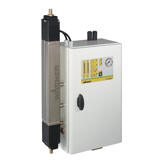
Page 17: Description
IP 5000 EDITION 08/2021 ORDER NUMBER DOC241936 DESCRIPTION DESIGN OF THE IP 5000 POWDER PUMP 5.1.1 IP 5000 VERSION Front View Profile P_04343 Designation 1 Control cabinet 2 Control panel 3 Cooling box for inlet valve air 4 Pressure regulator (in the control cabinet) -
Page 18: Ip 5000-Usd Version
IP 5000 EDITION 08/2021 ORDER NUMBER DOC241936 5.1.2 IP 5000-USD VERSION Front View Profile P_04825 Designation 1 Control cabinet 2 Control panel 3 Cooling box for inlet valve air 4 Pressure regulator (in the control cabinet) 5 Powder inlet valve... -
Page 19: Functioning
The powder pump is equipped with an active inlet valve cooling for gentle powder feeding. Mode of operation: The IP 5000 powder pump is a vacuum-assisted peristaltic pump. Feeding occurs by means of two pump hoses. The pump hoses are reciprocally sealed by pressure. Through generation of a vacuum, the pump hose is opened again and the powder is fed. -
Page 20: Operating Elements On Control Cabinet
The LEDs also light up when the pump is switched off with "ON/OFF" button 1 (serves for 24 VDC voltage monitoring). EXTENT OF DELIVERY Order no. Designation 241004 IP 5000 powder pump 2386088 IP 5000-USD powder pump The standard equipment includes: 241942 Declaration of Conformity... -
Page 21: Data
IP 5000 EDITION 08/2021 ORDER NUMBER DOC241936 DATA 5.5.1 TECHNICAL DATA Dimensions: Width 385 mm; 15.6 inch Height 760 mm; 29.92 inch Depth 202 mm; 8 inches Weight approx. 20.5 kg; 45.2 lbs Electrical: Mains 24 VDC±20% Input power 40 W... -
Page 22: Assembly And Commissioning
IP 5000 EDITION 08/2021 ORDER NUMBER DOC241936 ASSEMBLY AND COMMISSIONING TRAINING OF ASSEMBLY/COMMISSIONING PERSONNEL The assembly and commissioning personnel must have the technical skills to safely commission the device. When assembling, commissioning and carrying out all work, read and follow the operating manuals and safety regulations for the additionally required system components. -
Page 23: Assembly Example Of The Wagner Powder Center
IP 5000 EDITION 08/2021 ORDER NUMBER DOC241936 ASSEMBLY EXAMPLE OF THE WAGNER POWDER CENTER Pump mounted to the side using fastening set (accessory order no. 241550). P_00443 Measurements in mm... -
Page 24: Installation Recommendation
IP 5000 EDITION 08/2021 ORDER NUMBER DOC241936 INSTALLATION RECOMMENDATION 6.5.1 IP 5000 VERSION P_04306 Designation A Suction side (powder inlet) B Pressure side (powder outlet) 1 Maximum delivery head 5 m; 16.4 ft 2 Surge damper 3 Suction Lance 4 Fresh powder... -
Page 25: Ip 5000-Usd Version
IP 5000 EDITION 08/2021 ORDER NUMBER DOC241936 6.5.2 IP 5000-USD VERSION P_04826 Designation A Suction side (powder inlet) B Pressure side (powder outlet) 1 Suction length, maximum of 5 m; 16.4 ft 2 Surge damper 3 Suction Lance 4 Fresh powder... -
Page 26: Assembling The Powder Pump
IP 5000 EDITION 08/2021 ORDER NUMBER DOC241936 ASSEMBLING THE POWDER PUMP P_04344 Designation 1 Grounding screw 2 Plug connection 24 VDC and I/O signals 3 Compressed air connection 4 Plug connection of external cleaning box (accessory order no. 241570) - Page 27 IP 5000 EDITION 08/2021 ORDER NUMBER DOC241936 The powder pump is fixed next to the feed tank, for example the powder center or BigBag. P_04307 Work steps: 1. Mount the powder pump at installation location (fastening set order no. 241550, available as an accessory).
-
Page 28: How To Handle The Hose Coupling
Slide the powder hose onto the hose coupling as far as possible (up to the stop)! GROUNDING For safety reasons the system must be properly grounded. WAGNER recommends the use of a copper cable of at least 4 mm² with sufficient mechanical stability. - Page 29 IP 5000 EDITION 08/2021 ORDER NUMBER DOC241936 P_04308 Designation 1 Pressure regulator 1 2 Pressure regulator 2 3 Pressure regulator 3 A Switch position "0" (BigBag) B Switch position "1" (powder center) Factory settings: Operating mode: powder center Pressure regulator 1: 0.3 MPa;...
-
Page 30: Commissioning In Connection With The Powder Center
IP 5000 EDITION 08/2021 ORDER NUMBER DOC241936 6.9.1 COMMISSIONING IN CONNECTION WITH THE POWDER CENTER Work steps: 1. Set pressure on pressure regulator 1 (piston air KV) in the control cabinet (factory setting 0.3 MPa; 3 bar; 43.5 psi). Setting value: –... -
Page 31: Pin Assignment In The Control Cabinet
IP 5000 EDITION 08/2021 ORDER NUMBER DOC241936 6.9.3 PIN ASSIGNMENT IN THE CONTROL CABINET P_04309 Designation 1 DIP switches 1-8 (for setting, see Chapter 7.5.1) 2 LED display: "After-run, Level Controller" 3 A+ button/A- button 4 Valve connections 5 I/O connections... -
Page 32: Operation
– in conjunction with a powder center or BigBag – used as a transfer pump OPERATION WITH WAGNER POWDER CENTER The powder pump is controlled via the powder center controller. The powder pump is operated via the powder center touch screen (from PZ 2005). -
Page 33: Setting Elements In The Control Cabinet
IP 5000 EDITION 08/2021 ORDER NUMBER DOC241936 SETTING ELEMENTS IN THE CONTROL CABINET 7.5.1 DIP SWITCH FUNCTIONS Function No. Switch No. 8 Explanation 1 on = use of powder center* (hose lengths < 20 m) 1 off = use of BigBag* (hose lengths >... -
Page 34: Function 1 "Use Of Powder Center/Bigbag
IP 5000 EDITION 08/2021 ORDER NUMBER DOC241936 7.5.3 FUNCTION 1 "USE OF POWDER CENTER/BIGBAG" The setting to powder center or BigBag is dependent on the distance from the pump to the target tank. Note: For rising heights above 3 m; 9.9 ft select the "BigBag" setting. -
Page 35: Function 6 "Set Service Interval
IP 5000 EDITION 08/2021 ORDER NUMBER DOC241936 7.5.7 FUNCTION 6 "SET SERVICE INTERVAL" The service interval display is a useful auxiliary function for trouble-free operation of the pump. The factory settings are based on empirical values and are to be considered as non-binding guide values. -
Page 36: Setting Example
IP 5000 EDITION 08/2021 ORDER NUMBER DOC241936 7.5.8 SETTING EXAMPLE The "Powder center" operating mode is activated in the example. 4 LEDs light up on the display, which means that another 800 000 pump cycles can be executed until the fault message appears (factory setting 2 000 000 cycles - 800 000 possible cycles = 1 200 000 cycles have been executed). -
Page 37: Function 7 "Level Controller
IP 5000 EDITION 08/2021 ORDER NUMBER DOC241936 7.5.9 FUNCTION 7 "LEVEL CONTROLLER" The level controller serves to guarantee a consistent filling level in the powder tank. For this purpose an external level probe is connected, which sends the relevant signal to the powder pump controller. -
Page 38: Cycle Counter
IP 5000 EDITION 08/2021 ORDER NUMBER DOC241936 CYCLE COUNTER The powder pump is equipped with a cycle counter, which triggers a warning signal (fault LED flashes) after reaching a set number of pump cycles, prompting replacement of the valve and pump hoses. -
Page 39: Cleaning And Maintenance
The cleaning intervals should be adapted by the operator depending on the level of use and if necessary the level of soiling. If in doubt, we recommend contacting WAGNER's specialist personnel. 8.1.3 CLEANING IN CASE OF PAINT CHANGE In the case of a paint change, all powder feeding parts must be thoroughly cleaned. -
Page 40: External Cleaning Procedure
IP 5000 EDITION 08/2021 ORDER NUMBER DOC241936 8.1.5 EXTERNAL CLEANING PROCEDURE WARNING Bursting powder hose! Risk of injury and damage to the device. The powder hose may be loaded with a maximum pressure of 0.6 MPa; 6 bar; 87 psi. -
Page 41: Supercenter Cleaning Procedure
IP 5000 EDITION 08/2021 ORDER NUMBER DOC241936 8.1.6 SUPERCENTER CLEANING PROCEDURE The powder pump cleaning procedure, if used at a SuperCenter, is described below. To activate this function, the DIP switch 7 must be set to "on" (see Chapter 7.5.1). -
Page 42: Maintenance
Incorrect maintenance/repair! Danger to life and equipment damage. Only a WAGNER service center or a specially trained person may carry out repairs and replace parts. Only repair and replace parts that are listed in the "Spare parts" chapter and that are assigned to the device. -
Page 43: Changing Valve And Pump Hoses
IP 5000 EDITION 08/2021 ORDER NUMBER DOC241936 8.2.5 CHANGING VALVE AND PUMP HOSES P_00020 Work steps: 1. Switch off the system. 2. Switch off the main switch and protect against unauthorized restarting. 3. Lock the compressed air supply and decompress the system. - Page 44 IP 5000 EDITION 08/2021 ORDER NUMBER DOC241936 P_00008 7. Unscrew screws 2 on the upper valve block. 8. Remove Y-piece 3 and valve housing 4 at the top of the pump body 5. 9. Unscrew screws (2) on the lower valve block.
- Page 45 IP 5000 EDITION 08/2021 ORDER NUMBER DOC241936 P_00010 13. Unscrew screws 8 on the upper and lower hose flange 9. 14. Remove hose flanges 9 at the top and bottom of the pump body 5. P_00011 15. Squeeze old pump hoses 10 lightly at the top and remove downwards from the pump body 5.
- Page 46 IP 5000 EDITION 08/2021 ORDER NUMBER DOC241936 View from top P_00013 The pump hoses must not be mounted twisted (observe ridges A). Press hose collar at the top and bottom against the wall with your fingers. P_00014 17. Attach hose flange 9 to the bottom of the pump body 5 and fasten with screws 8.
- Page 47 IP 5000 EDITION 08/2021 ORDER NUMBER DOC241936 Tightness check: The tightness check is not essential and should be performed only by qualified personnel. P_04346 20. Remove plugs (4 pieces) from the valves 12. 21. Open the compressed air supply. 22. Set blow-out air on pressure regulator 13 to 0 MPa; 0 bar; 0 psi.
- Page 48 IP 5000 EDITION 08/2021 ORDER NUMBER DOC241936 P_00008 27. Fit upper valve housing 4 and Y-piece 3 to the top of the pump body 5 and fasten with screws 2. Evenly tighten screws (2) alternately crosswise. (6 Nm; 4.425 lb ft).
-
Page 49: Storage Conditions For Pump And Valve Hoses
IP 5000 EDITION 08/2021 ORDER NUMBER DOC241936 P_00015 28. Fit lower valve housing (4) and Y-piece (3) to the bottom of the pump body (5) and fasten with screws (2). Evenly tighten screws (2) alternately crosswise. (6 Nm; 4.425 lb ft). -
Page 50: Replacing The Non-Return Valves
IP 5000 EDITION 08/2021 ORDER NUMBER DOC241936 REPLACING THE NON-RETURN VALVES Non-return valve 241237 Non-return valve 2409407 (up to serial number 1847) (up to serial number 1848) P_04349 P_04350 8.4.1 DISASSEMBLY P_00020 Work steps: 1. Switch off the system. 2. Switch off the main switch and protect against unauthorized restarting. - Page 51 IP 5000 EDITION 08/2021 ORDER NUMBER DOC241936 P_04329 6. Unscrew screws (4) on the lower valve block. 7. Remove Y-piece (3) and valve housing (2) at the bottom of the pump body (1). P_04331 8. Turn back connections (5) on the non-return valves up to stop.
- Page 52 IP 5000 EDITION 08/2021 ORDER NUMBER DOC241936 P_04333 9. Unscrew screws (7) on the lower valve block and remove hose flange (6) from pump body (1). P_04334 10. Remove valves (10) (AL1 and AL2) from the air connections. 11. Unscrew air connections (8) out of the non-return valve units (9) and dismount non-return valves.
-
Page 53: Assembly
IP 5000 EDITION 08/2021 ORDER NUMBER DOC241936 8.4.2 ASSEMBLY P_04335 Work steps: 1. Screw in non-return valve (12) up to stop in bushing (11). P_04336 2. Mount non-return valve (9) with air connection (8) in control cabinet and screw them loosely together. - Page 54 IP 5000 EDITION 08/2021 ORDER NUMBER DOC241936 4. Loosely screw the non-return valve connections into the air connections in the hose bushing (6) with care. 5. Evenly tighten screws 7 crosswise (5 Nm; 3.7 lb ft). 6. Screw the non-return valve connections completely into the air connections in the hose bushing (6).
- Page 55 IP 5000 EDITION 08/2021 ORDER NUMBER DOC241936 P_04338 8. Fit lower valve housing (2) and Y-piece (3) to the bottom of the pump body (1) and fasten with screws (4). 9. Evenly tighten screws (4) alternately crosswise. (6 Nm; 4.43 lb ft).
-
Page 56: Trouble Shooting And Solution
WAGNER devices, protective systems and safety, monitoring and control equipment may only be serviced/repaired as defined in Directive 2014/34/EC (ATEX) by trained WAGNER service personnel or skilled persons in accordance with TRBS 1203! Note national regulations! Service, repair or replacement of devices or parts of devices may only be performed... -
Page 57: Disassembly And Disposal
WAGNER or one of our dealers will take back your used WAGNER electric or electronic equipment and will dispose of it for you in an environmentally-friendly way. -
Page 58: Accessories
Consists of: – suspension bracket for wall mounting – 2 rubber buffers P_00440 241555 Surge damper – for use in the WAGNER circulating powder center – reduced dust formation P_01034 265110 Suction device, IP 5000 2301550 Suction lance, SN600/14 for powder center... - Page 59 ORDER NUMBER DOC241936 Order no. Designation 241565 Parking station P_00447 241570 External cleaning box P_00449 3313075 Pump rack, IP 5000 P_00499 390955 Hose take-up, D10-D12, not electrically conductive P_01035 2305866 Hose take-up, D10-D12, electrically conductive P_01035 2353080 Coupling piece, electrically conductive...
- Page 60 IP 5000 EDITION 08/2021 ORDER NUMBER DOC241936 Order no. Designation 9987135 Hose holder for POE 12 and POE 14 powder hoses 2301253 Thread adapter 2305865 – for the seating of a complete coupling P_00924 2310700 Powder hose, POE 12 2312126...
-
Page 61: Spare Parts
DANGER Incorrect maintenance/repair! Danger to life and equipment damage. Only a WAGNER service center or a specially trained person may carry out repairs and replace parts. Use only WAGNER original spare parts and accessories. Only repair and replace parts that are listed in the "Spare parts" chapter and that are assigned to the device. -
Page 62: Powder Pump Spare Parts List
IP 5000 EDITION 08/2021 ORDER NUMBER DOC241936 12.2 POWDER PUMP SPARE PARTS LIST P_04347... - Page 63 IP 5000 EDITION 08/2021 ORDER NUMBER DOC241936 Order no. Designation 2312057 Service set pump hose D33 x 401 (2 hoses) 2301442 Hose flange inlet valve 241486 Hose flange outlet valve 2301449 Valve housing 2312058 Service set valve hose D15 x 25 x 74 (2 hoses)
-
Page 64: Control Cabinet Spare Parts List
IP 5000 EDITION 08/2021 ORDER NUMBER DOC241936 12.3 CONTROL CABINET SPARE PARTS LIST 17/18 10/25/26 13/14 15/20 P_04348 Note: With the IP 5000-USD, the control cabinet is arranged rotated by 180°. - Page 65 IP 5000 EDITION 08/2021 ORDER NUMBER DOC241936 Order no. Designation 360931 PCB display, complete ET (Note installation direction for USD variant) 2305520 Print, complete IP 5000 ET 360458 Ribbon cable, Flex-Flat 8-pin 241526 Blowing out box 9943152 Double 3/2-way valve 9943157...
-
Page 66: Connecting Plug Spare Parts List
IP 5000 EDITION 08/2021 ORDER NUMBER DOC241936 12.4 CONNECTING PLUG SPARE PARTS LIST P_00024 Order no. Designation 9956254 Externally-mounted housing 9956253 Pin insert, 10-pin 9956252 Bushing insert, 10-pin 9906029 Socket cap screw 241545 Grommet housing, 10-pin 3156891 Cable connection 9956273... -
Page 67: Sn 600/14 Suction Lance Spare Parts List
IP 5000 EDITION 08/2021 ORDER NUMBER DOC241936 12.5 SN 600/14 SUCTION LANCE SPARE PARTS LIST ∅30 P_00448 Measurement X order no. 2301550 582 mm Order no. Designation 265412 Fluid ring 2301098 Crown, M18x1.5 2353080 Coupling piece, complete 9992260 Coupling plug... -
Page 68: Sn 1500/14 Suction Lance Spare Parts List
IP 5000 EDITION 08/2021 ORDER NUMBER DOC241936 12.6 SN 1500/14 SUCTION LANCE SPARE PARTS LIST ∅30 P_01033 Measurement X order no. 2301548 1518 mm Order no. Designation 265412 Fluid ring 2304065 Suction head 2353080 Coupling piece, complete 9992260 Coupling plug... -
Page 69: External Cleaning Box Spare Parts List
IP 5000 EDITION 08/2021 ORDER NUMBER DOC241936 12.7 EXTERNAL CLEANING BOX SPARE PARTS LIST P_00438 Order no. Designation 9956234 Solenoid valve, EVP 342 9943158 Non-return valve, d10 390954 Coupling piece, complete Wearing parts... -
Page 70: Circuit Diagrams
IP 5000 EDITION 08/2021 ORDER NUMBER DOC241936 13 CIRCUIT DIAGRAMS 13.1 PLUG ASSIGNMENT XST 9 P_04316 Assignment Function Plug Device voltage supply Device grounding Release (+24 V signal) Powder pump START/STOP +24 V = ON; 0 V = OFF Cleaning ON/OFF... -
Page 71: Signal Sequence
IP 5000 EDITION 08/2021 ORDER NUMBER DOC241936 13.2 SIGNAL SEQUENCE 13.2.1 SIGNAL SEQUENCE "FEEDING OPERATION" Signal I1/O1 P_04317 State 1 OFF 2 ON 13.2.2 SIGNAL SEQUENCE "KPZ 2008 CLEANING" DIP switch 7 is set to "off". Signal I2 P_04318 Cleaning ends automatically... -
Page 72: Signal Sequence "Pxm/Pxs Standard Cleaning
IP 5000 EDITION 08/2021 ORDER NUMBER DOC241936 13.2.3 SIGNAL SEQUENCE "PXM/PXS STANDARD CLEANING" DIP switch 7 is set to "on". T1=200 ms P_04325 Description 1 I2 Cleaning on/off 2 I4 Level controller input 3 O2 Cleaning in process 4 Start... -
Page 73: Signal Sequence "Pxm/Pxs Intensive Cleaning
IP 5000 EDITION 08/2021 ORDER NUMBER DOC241936 13.2.4 SIGNAL SEQUENCE "PXM/PXS INTENSIVE CLEANING" DIP switch 7 is set to "on". 0 ms < T < T1 T1=200 ms P_04326 Description 1 I2 Cleaning on/off 2 I4 Level controller input 3 O2 Cleaning in process... -
Page 74: Signal Sequence "Supercenter Cleaning
IP 5000 EDITION 08/2021 ORDER NUMBER DOC241936 13.2.5 SIGNAL SEQUENCE "SUPERCENTER CLEANING" DIP switch 7 is set to "on". P_04327 Description 1 I2 Cleaning on/off 2 I4 Level controller input 3 O2 Cleaning in process 4 Start cleaning... -
Page 75: Valve Assignment
IP 5000 EDITION 08/2021 ORDER NUMBER DOC241936 13.3 VALVE ASSIGNMENT Inlet valve 1 Piston valve 1 Vacuum valve 1 Pump tube 1 Blow-out valve 1 Outlet valve 1 Inlet valve 2 Piston valve 2 Vacuum valve 2 Pump tube 2... -
Page 76: Electrical Circuit Diagrams
IP 5000 EDITION 08/2021 ORDER NUMBER DOC241936 13.4 ELECTRICAL CIRCUIT DIAGRAMS P_00028... - Page 77 IP 5000 EDITION 08/2021 ORDER NUMBER DOC241936 P_00029...
- Page 78 IP 5000 EDITION 08/2021 ORDER NUMBER DOC241936 P_00030...
- Page 79 IP 5000 EDITION 08/2021 ORDER NUMBER DOC241936 P_00031...
- Page 80 IP 5000 EDITION 08/2021 ORDER NUMBER DOC241936 P_00032...
- Page 81 IP 5000 EDITION 08/2021 ORDER NUMBER DOC241936 P_00033...
- Page 82 IP 5000 EDITION 08/2021 ORDER NUMBER DOC241936 P_00034...
-
Page 83: Pneumatic Diagram
IP 5000 EDITION 08/2021 ORDER NUMBER DOC241936 13.5 PNEUMATIC DIAGRAM P_00026... - Page 84 IP 5000 EDITION 08/2021 ORDER NUMBER DOC241936 Number Description EV1 inlet valve 1 AL1 blow-out valve 1 VK1 vacuum valve 1 KV1 piston valve 1 AV 1 outlet valve 1 EV 2 inlet valve 2 AL2 blow-out valve 2 VK2 vacuum valve 2...
-
Page 85: Eu Declaration Of Conformity
II 3D Ex tc IIIB T85°C Dc EU Declaration of Conformity The EU Declaration of Conformity is enclosed with this product. If needed, further copies can be ordered through your WAGNER dealer by specifying the product name and serial number. Order number:... - Page 88 Order no. 241936 Edition 08/2021 ts-powder@wagner-group.com www.wagner-group.com...
Need help?
Do you have a question about the IP 5000 and is the answer not in the manual?
Questions and answers