Sign In
Upload
Download
Table of Contents
Contents
Add to my manuals
Delete from my manuals
Share
URL of this page:
HTML Link:
Bookmark this page
Add
Manual will be automatically added to "My Manuals"
Print this page
×
Bookmark added
×
Added to my manuals
Manuals
Brands
WAGNER Manuals
Industrial Equipment
PXM
Operating and assembly manual
WAGNER PXM Operating And Assembly Manual
Powder center
Hide thumbs
1
2
Table Of Contents
3
4
5
6
7
8
9
10
11
12
13
14
15
16
17
18
19
20
21
22
23
24
25
26
27
28
29
30
31
32
33
34
35
36
37
38
39
40
41
42
43
44
45
46
47
48
49
50
51
52
53
54
55
56
57
58
59
60
61
62
63
64
65
66
67
68
69
70
71
72
73
74
75
76
77
78
79
80
81
82
83
84
85
86
87
88
89
90
91
92
93
94
95
96
97
98
99
100
101
102
103
104
105
106
107
108
109
110
111
112
113
114
115
116
117
118
119
120
121
122
123
124
125
126
127
128
129
130
131
132
133
134
135
136
137
138
139
140
141
142
143
144
145
146
147
148
149
150
151
152
153
154
155
156
157
158
159
160
page
of
160
Go
/
160
Contents
Table of Contents
Troubleshooting
Bookmarks
Table of Contents
Table of Contents
1 About These Instructions
Preface
Warnings, Notices, and Symbols in this Operating Manual
Languages
Abbreviations
Terminology for the Purpose of this Manual
2 Correct Use
Device Type
Type of Use
Use in Potentially Explosive Areas
Safety Parameters
Processible Working Materials
Reasonably Foreseeable Misuse
Residual Risks
3 Identification
Explosion Protection Identification
Permissible Device Combinations
Type Plate
Note on the Ex-Zone Classification by the Operator
4 General Safety Instructions
Safety Instructions for the Operator
Electrical Devices and Equipment
Personnel Qualifications
Safe Work Environment
Safety Instructions for Staff
Safe Handling of WAGNER Powder Spray Devices
Grounding the Device
Product Hoses
Cleaning
Handling Powder Lacquers
5 Description
Components
Version with Integrated Filter
Version for Final Filter
Version with Ultrasonic Sieve
Mode of Operation
Protective and Monitoring Equipment
Scope of Delivery
Design Variants of the PXM Powder Center
Type with Ultrasonic Screening Unit
Installation Dimensions for Ultrasonic Screening Unit
Technical Data
Controls
Screen Layout of the Touch Screen
Explanation of the Screen Page Numbers
Inputs on the Touch Panel
Displays on the Warning Lamp
User Rights
6 Assembly and Commissioning
Training the Assembly Staff
Storage Conditions
Installation Conditions
Transportation
Assembly and Installation
Grounding
Safety Checks
Commissioning
Standard Settings
Machine Parameters Operation
Machine Parameter Cleaning
CAN Addresses for MCM System
EPG S2 Settings
Function Test
7 Operation
Training the Operating Staff
Safety Instructions
Touch Screen Operation Standard Equipment
Equipment with Final Filter
Equipment with Integrated Exhaust System
Set Language
Logging a User On/Off
Starting/Stopping Coating
Paint Change Components
Cleaning Positions Powder Hoses
Configuring the Powder Center
Settings
Machine Parameters Operation
Machine Parameter Cleaning
Machine Parameters Diagnosis
System
8 Cleaning and Maintenance
Cleaning
Cleaning Staff
Safety Instructions
Paint Change
Paint Change Components
Cleaning Positions Powder Hoses
Cleaning Functions
Cleaning Parameters
Start Cleaning (Example: Profitech M)
Cleaning/Paint Change on the PXM with Ultrasonic Sieve
Maintenance
Maintenance Staff
Safety Instructions
Maintenance Procedures
Safety Checks
Grounding Check
9 Troubleshooting and Rectification
Fault Messages
Types of Fault Messages
Current
History
10 Repair
Repair Personnel
Safety Instructions
11 Function Test after the Repair
12 Inspections in Accordance with Din en 50177: 2010
13 Disassembly and Disposal
14 Accessories
15 Spare Parts
How Can Spare Parts be Ordered
Workstation 22 Injectors
Workstation 20 Injectors with Fluidization
Workstation 34 Injectors
Cylinder Workstation (22 Injectors)
Cylinder Workstation (34 Injectors)
Scraper Assembly Intake Tubes
Cleaning System Tank Version (22 Injectors)
Cleaning System Box Version (22 Injectors)
Vibration Table
Feed Lance
Vibrating Table Fresh Powder
Compressed Air Tank for 22 Injectors (1 Outlet)
Compressed Air Tank for 22 Injectors
Compressed Air Tank for 34 Injectors
Pressure Regulator, Complete
Powder Tank, Fluidized (22 Injectors)
Final Filter Adapter
Exhaust System Throttle Valve
Exhaust System Throttle Valve (Version with US Sieve)
Housing
Control Unit Cabinet (1 IP 5000)
Control Unit Cabinet (2 IP 5000)
Control Unit Cabinet (18 EPG)
Control Unit Cabinet Control Panel
LED Lamp 1500
Led Lamp 700
Final Filter
PI-F1 Powder Injector
PI-P1 Powder Injector
Hicoat-ED Pump P
Hicoat-ED Pump F
Fresh Powder Feed Unit
Ultrasonic Screening Unit
Level Sensor
16 Warranty Declaration and Declaration of Incorporation
Important Notes Regarding Product Liability
Warranty Claim
Declaration of Incorporation (Statement of Conformity)
17 Electrical Connection Plans
Advertisement
Quick Links
1
Fault Messages
Download this manual
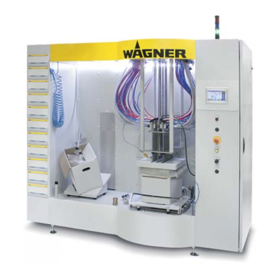
Powder Center
Translation of the Original
Operating and Assembly
Manual
PXM
Version 08 / 2015
P_02519
P_02519
Table of
Contents
Previous
Page
Next
Page
1
2
3
4
5
Advertisement
Table of Contents
Need help?
Do you have a question about the PXM and is the answer not in the manual?
Ask a question
Questions and answers
Related Manuals for WAGNER PXM
Control Unit WAGNER EPG-SPRINT Original Service Manual
Universal control unit for powder coating guns (108 pages)
Control Unit WAGNER EPG-SPRINT X Operating Manual
Universal control unit for powder guns (104 pages)
Water Pump WAGNER IP 5000 Translation Of The Original Operating Manual
Fresh powder and transfer pump (88 pages)
Control Unit WAGNER EPG S2 Translation Of The Original Operating Manual
Universal control unit for powder coating guns (60 pages)
Controller WAGNER EPG S2 Translation Of The Original Operating Manual
Universal control unit for powder spray guns (48 pages)
Laboratory Equipment WAGNER PI-P1 Operating Manual
Powder injectors (20 pages)
Industrial Equipment WAGNER PEA-C4-HiCoat Translation Of The Original Operating Manual
Automatic powder gun (60 pages)
Industrial Equipment WAGNER MCC Operating And Assembly Manual
Powder center (160 pages)
Industrial Equipment WAGNER VU 1 Translation Of The Original Operating And Assembly Manual
Reciprocator (104 pages)
Industrial Equipment WAGNER Basic 8000 Translation Of The Original Operating Manual
Spray wall (48 pages)
Industrial Equipment WAGNER DSD12 Operating Manual
Triple-cutter turning head (12 pages)
This manual is also suitable for:
Pi-f1
Hi-coat ed
Ip 5000
Epg s2
Epg-sprint x
Mcc
...
Show all
Mcs 1
Cpd 1
Table of Contents
Save PDF
Print
Rename the bookmark
Delete bookmark?
Delete from my manuals?
Login
Sign In
OR
Sign in with Facebook
Sign in with Google
Upload manual
Upload from disk
Upload from URL


Need help?
Do you have a question about the PXM and is the answer not in the manual?
Questions and answers