
Related Manuals for Endress+Hauser Proline Promass 84 MODBUS RS485


Summary of Contents for Endress+Hauser Proline Promass 84 MODBUS RS485
- Page 1 Operating Instructions Proline Promass 84 MODBUS RS485 Coriolis Mass Flow Measuring System for Custody Transfer BA129D/06/en/06.10 71116482 Valid as of version V 3.06.XX (Device software)
-
Page 3: Table Of Contents
Proline Promass 84 MODBUS RS485 Table of contents Table of contents Safety instructions ....5 Operation ..... . 29 Designated use . - Page 4 Proline Promass 84 MODBUS RS485 Table of contents Custody transfer measurement ..69 Suitability for custody transfer, metrological control, obligation to subsequent verification ..69 7.1.1 Approval for custody transfer ... 69 7.1.2 Special features of working in the...
-
Page 5: Safety Instructions
• The device must be operated by persons authorized and trained by the facility's owner-operator. Strict compliance with the instructions in the Operating Instructions is mandatory. • Endress+Hauser will be happy to assist in clarifying the corrosion resistance properties of materials wetted by special fluids, including fluids used for cleaning. However, small changes of temperature, concentration or degree of contamination in the process can result in differences in corrosion resistance. -
Page 6: Return
• The manufacturer reserves the right to modify technical data without prior notice. Your Endress+Hauser representative will supply you with current information and updates to these Operating Instructions. • The separate document on the Pressure Equipment Directive must be observed for devices used in Category II, III or IV installations in accordance with the Pressure Equipment Directive. -
Page 7: Identification
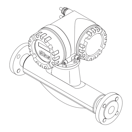
Proline Promass 84 MODBUS RS485 Identification Identification Device designation The "Promass 84" flow measuring system consists of the following components: • Promass 84 transmitter • Promass F, Promass M, Promass A sensors Two versions are available: • Compact version: transmitter and sensor form a single mechanical unit. -
Page 8: Nameplate Of The Sensor
Identification Proline Promass 84 MODBUS RS485 2.1.2 Nameplate of the sensor PROMASS F 83F25-XXXXXXXXXXXX Order Code: 12345678901 Ser.No.: ABCDEFGHJKLMNPQRST TAG No.: 2.5100 / -11 DN25 / 1" K-factor: Size: DN25 DIN/EN PN100 pnom =PS= 100bar 1.4404 / 316L, 1.4539 / 904L Materials: -50°C...+200°C / -58°F...+392°F... -
Page 9: Nameplate For Connections
Proline Promass 84 MODBUS RS485 Identification 2.1.4 Nameplate for connections active See operating manual passive Betriebsanleitung beachten normally open contact Observer manuel d'instruction normally closed contact XXXXXXXXXXX Ser.No.: L1/L+ Supply / Versorgung / N/L- Tension d'alimentation 26 = B (RxD/TxD-P) -
Page 10: Certificates And Approvals
Regulation and Laboratory Procedures" and with the EMC requirements of IEC/EN 61326. The measuring system described in these Operating Instructions thus complies with the statutory requirements of the EC Directives. Endress+Hauser confirms successful testing of the device by affixing to it the CE mark. -
Page 11: Installation
Proline Promass 84 MODBUS RS485 Installation Installation Incoming acceptance, transport and storage 3.1.1 Incoming acceptance On receipt of the goods, check the following points: • Check the packaging and the contents for damage. • Check the shipment, make sure nothing is missing and that the scope of supply matches your order. -
Page 12: Storage
Installation Proline Promass 84 MODBUS RS485 3.1.3 Storage Note the following points: • Pack the measuring device in such a way as to protect it reliably against impact for storage (and transportation). The original packaging provides optimum protection. • The permitted storage temperature is range is –40 to +80 °C (–40 to +176 °F), preferably +20 °C (+68 °F). - Page 13 Proline Promass 84 MODBUS RS485 Installation Installation in a vertical pipe The proposed configuration in the following diagram, however, permits installation in a vertical pipeline. Pipe restrictors or the use of an orifice plate with a smaller cross-section than the nominal diameter prevent the sensor from running empty during measurement.
-
Page 14: Orientation
Installation Proline Promass 84 MODBUS RS485 3.2.3 Orientation Make sure that the direction of the arrow on the nameplate of the sensor matches the direction of flow (direction in which the fluid flows through the pipe). Orientation Promass A Vertical: Recommended orientation with upward direction of flow. - Page 15 Proline Promass 84 MODBUS RS485 Installation Fig. V: Vertical orientation ÃÃ ÃÃ ÃÃ ÃÃ a0004572 Fig. H1: Horizontal orientation Transmitter head up ✘ Ã ÃÃ ÃÃ TM = >200 °C TM = >200 °C (>392 °F) (>392 °F) a0004576 Fig. H2: Horizontal orientation Transmitter head down ÃÃ...
-
Page 16: Heating
– Relative magnetic permeability μ – Plate thickness d ≥ 0.35 mm (≥ 0.014") • Information on permissible temperature ranges → ä 107 Special heating jackets which can be ordered as accessories from Endress+Hauser are available for the sensors. Endress+Hauser... -
Page 17: Thermal Insulation
Proline Promass 84 MODBUS RS485 Installation 3.2.5 Thermal insulation Some fluids require suitable measures to avoid loss of heat at the sensor. A wide range of materials can be used to provide the required thermal insulation. a0004614-ae Fig. 10: In the case of the Promass F high-temperature version, a maximum insulation thickness of 60 mm (2.4") must be observed in the area of the electronics/neck. -
Page 18: Installation Instructions
Installation Proline Promass 84 MODBUS RS485 Installation instructions 3.3.1 Turning the transmitter housing Turning the aluminum field housing Warning! The turning mechanism in devices with EEx d/de or FM/CSA Cl. I Div. 1 classification is not the same as that described here. The procedure for turning these housings is described in the Ex-specific documentation. -
Page 19: Installing The Wall-Mount Housing
Proline Promass 84 MODBUS RS485 Installation 3.3.2 Installing the wall-mount housing There are various ways of installing the wall-mount housing: • Mounted directly on the wall • Installation in control panel (separate mounting set, accessories) → ä 20 • Pipe mounting (separate mounting set, accessories) → ä 20 "... - Page 20 Installation Proline Promass 84 MODBUS RS485 Panel mounting Prepare the opening in the panel as illustrated in the diagram. Slide the housing into the opening in the panel from the front. Screw the fasteners onto the wall-mount housing. Screw threaded rods into holders and tighten until the housing is solidly seated on the panel wall.
-
Page 21: Turning The Local Display
Proline Promass 84 MODBUS RS485 Installation 3.3.3 Turning the local display Unscrew cover of the electronics compartment from the transmitter housing. Press the side latches on the display module and remove the module from the electronics compartment cover plate. Rotate the display to the desired position (max. 4 x 45 ° in both directions), and reset it onto the electronics compartment cover plate. -
Page 22: Wiring
Wiring Warning! When connecting Ex-certified devices, see the notes and diagrams in the Ex-specific supplement to these Operating Instructions. Please do not hesitate to contact your Endress+Hauser sales office if you have any questions. Note! The measuring instrument does not have an internal disconnecting device. Therefore, assign a switch or circuit breaker to the measuring instrument with which the voltage supply line can be disconnected from the power system. -
Page 23: Shielding And Grounding
Proline Promass 84 MODBUS RS485 Wiring 4.1.1 Shielding and grounding When planning the shielding and grounding for a fieldbus system, there are three important points to consider: • Electromagnetic compatibility (EMC) • Explosion protection • Safety of the personnel To ensure the optimum electromagnetic compatibility of systems, it is important that the system components and above all the cables, which connect the components, are shielded and that no portion of the system is unshielded. -
Page 24: Connecting The Remote Version
Wiring Proline Promass 84 MODBUS RS485 Connecting the remote version 4.2.1 Connecting connecting cable for sensor/transmitter Warning! • Risk of electric shock. Switch off the power supply before opening the device. Do not install or wire the device while it is connected to the power supply. -
Page 25: Cable Specification, Connecting Cable
Proline Promass 84 MODBUS RS485 Wiring 4.2.2 Cable specification, connecting cable The specifications of the cable connecting the transmitter and the sensor of the remote version are as follows: • 6 x 0.38 mm PVC cable with common shield and individually shielded cores •... - Page 26 Wiring Proline Promass 84 MODBUS RS485 – 27 + 26 – 25 + 24 – 23 + 22 – 21 + 20 N (L-) L1 (L+) a0004584 Fig. 19: Connecting the transmitter (stainless steel field housing); cable cross-section: max. 2.5 mm Cable for power supply: 85 to 260 V AC, 20 to 55 V AC, 16 to 62 V DC Terminal No.
-
Page 27: Terminal Assignment
Proline Promass 84 MODBUS RS485 Wiring 4.3.2 Terminal assignment " Caution! Only certain combinations of submodules (see Table) on the I/O board are permissible. The individual slots are marked and assigned to the following terminals in the connection compartment of the transmitter: •... -
Page 28: Post-Connection Check
Wiring Proline Promass 84 MODBUS RS485 Post-connection check Perform the following checks after completing electrical installation of the measuring device: Device condition and specifications Notes Are cables or the device damaged (visual inspection)? Electrical connection Notes Does the supply voltage match the specifications on the nameplate? -
Page 29: Operation
Proline Promass 84 MODBUS RS485 Operation Operation Quick operation guide You have a number of options for configuring and commissioning the device: Local display (option) → ä 30 The local display enables you to read all important variables directly at the measuring point, configure bus-specific and device-specific parameters in the field and perform commissioning. -
Page 30: Display And Operating Elements
Operation Proline Promass 84 MODBUS RS485 Display and operating elements The local display enables you to read all important parameters directly at the measuring point and configure the measuring instrument using the "Quick Setup" or the function matrix. The display consists of four lines; this is where measured values and/or status variables (direction of flow, empty pipe, bar graph, etc.) are displayed. -
Page 31: Display (Operating Mode)
Proline Promass 84 MODBUS RS485 Operation 5.2.1 Display (operating mode) The display area consists of three lines in all; this is where measured values are displayed, and/or status variables (direction of flow, bar graph, etc.). You can change the assignment of display lines to different variables to suit your needs and preferences (→... -
Page 32: Icons
Operation Proline Promass 84 MODBUS RS485 5.2.3 Icons The icons which appear in the field on the left make it easier to read and recognize measured variables, device status, and error messages Icon Meaning Icon Meaning System error Process error... -
Page 33: Brief Operating Instructions To The Function Matrix
Proline Promass 84 MODBUS RS485 Operation Brief operating instructions to the function matrix Note! • See the general notes → ä 34 • Function descriptions → see the "Description of Device Functions" manual HOME position → F → Entry into the function matrix Select a block (e.g. -
Page 34: General Notes
• If programming is disabled and the P operating elements are pressed in any function, a prompt for the code automatically appears on the display. • If "0" is entered as the customer's code, programming is always enabled! • Your Endress+Hauser representative can be of assistance if you mislay your personal code. " Caution! Changing certain parameters such as all sensor characteristics, for example, influences numerous functions of the entire measuring system, particularly measuring accuracy. -
Page 35: Error Messages
Proline Promass 84 MODBUS RS485 Operation Error messages 5.4.1 Type of error Errors that occur during commissioning or measuring are displayed immediately. If two or more system or process errors occur, the error with the highest priority is the one shown on the display. -
Page 36: Modbus Rs485 Communication
Operation Proline Promass 84 MODBUS RS485 MODBUS RS485 communication 5.5.1 MODBUS RS485 technology The MODBUS is an open, standardized fieldbus system which is deployed in the areas of manufacturing automation, process automation and building automation. System architecture The MODBUS RS485 is used to specify the functional characteristics of a serial fieldbus system with which distributed, digital automation systems are networked together. - Page 37 Proline Promass 84 MODBUS RS485 Operation Master/slave communication A distinction is made between two methods of communication with regard to master/slave communication via MODBUS RS485: • Polling (request-response-transaction) The master sends a request telegram to one slave and waits for the slave's response telegram.
-
Page 38: Modbus Telegram
Operation Proline Promass 84 MODBUS RS485 5.5.2 MODBUS telegram General The master-slave process is used for data exchange. Only the master can initiate data transmission. Following the prompt, the slave sends the master the necessary data as a response telegram or executes the command requested by the master. -
Page 39: Modbus Function Codes
Proline Promass 84 MODBUS RS485 Operation 5.5.3 MODBUS function codes The function code determines which read, write and test operations should be executed by means of the MODBUS protocol. The measuring device supports the following function codes: Function Name in accordance with... -
Page 40: Modbus Register Addresses
Operation Proline Promass 84 MODBUS RS485 5.5.5 MODBUS register addresses Each device parameter has its own register address. The MODBUS master uses this register address to talk to the individual device parameters and access the device data. The register addresses of the individual device parameters can be found in the "Description of Device Functions"... - Page 41 Proline Promass 84 MODBUS RS485 Operation Data types The following data types are supported by the measuring device: • FLOAT (floating-point numbers IEEE 754) Data length = 4 bytes (2 registers) Byte 3 Byte 2 Byte 1 Byte 0 SEEEEEEE...
-
Page 42: Modbus Error Messages
Operation Proline Promass 84 MODBUS RS485 INTEGER: Sequence Selection 1 – 0 – 3 – 2 * Byte 1 Byte 0 3 – 2 – 1 – 0 (MSB) (LSB) 0 – 1 – 2 – 3 Byte 0 Byte 1 2 –... -
Page 43: Modbus Auto-Scan Buffer
Proline Promass 84 MODBUS RS485 Operation 5.5.7 MODBUS auto-scan buffer Function description The MODBUS master uses the request telegram to access the device parameters (data) of the measuring device. Depending on the function code, the master gains read or write access to a single device parameter or a group of consecutive device parameters. - Page 44 Operation Proline Promass 84 MODBUS RS485 Scan list MODBUS configuration Configuration via Register address local operation / configuration program (BASIC FUNCTION → MODBUS RS485 →) (data type = Integer) 5013 SCAN LIST REG. 13 5014 SCAN LIST REG. 14 5015 SCAN LIST REG.
- Page 45 Proline Promass 84 MODBUS RS485 Operation Response time The response time when accessing the data area (register addresses 5051 to 5081) is typically between 3 and 5 ms. Note! It may take longer for a command to be executed in the device. The data is not updated until the command has been executed.
- Page 46 Operation Proline Promass 84 MODBUS RS485 2. Access to data via MODBUS By specifying the register start address 5051 and the number of registers, the MODBUS master can read out the measured values with just one request telegram. Data area...
-
Page 47: Operating Options
5.6.1 Operating program "FieldCare" FieldCare is Endress+Hauser’s FDT-based plant asset management tool and allows the configuration and diagnosis of intelligent field devices. By using status information, you also have a simple but effective tool for monitoring devices. The Proline flowmeters are accessed via a service interface or via the service interface FXA193 with Proline Adapter Cable. -
Page 48: Hardware Settings
Operation Proline Promass 84 MODBUS RS485 Hardware settings Warning! In the case of explosion-protected equipment, observe a cooling or discharge time of 10 minutes before opening the device. 5.7.1 Switching hardware write protection on/off A jumper on the I/O board provides the means of switching hardware write protection on or off. -
Page 49: Configuring The Device Address
Proline Promass 84 MODBUS RS485 Operation 5.7.2 Configuring the device address The device address must always be configured for a MODBUS slave. The valid device addresses are in a range from 1 to 247. In a MODBUS RS485 network, each address can only be assigned once. -
Page 50: Configuring The Terminating Resistors
Operation Proline Promass 84 MODBUS RS485 5.7.3 Configuring the terminating resistors It is important to terminate the MODBUS RS485 line correctly at the start and end of the bus segment since impedance mismatch results in reflections on the line which can cause faulty communication transmission. -
Page 51: Current Output Configuration
Proline Promass 84 MODBUS RS485 Operation 5.7.4 Current output configuration The current output is configured as "active" or "passive" by means of various jumpers on the current submodule. Warning! Risk of electric shock. Exposed components carry dangerous voltages. Make sure that the power supply is switched off before you remove the cover of the electronics compartment. -
Page 52: Relay Output Configuration
Operation Proline Promass 84 MODBUS RS485 5.7.5 Relay output configuration The relay contact can be configured as normally open (NO or make) or normally closed (NC or break) contacts by means of two jumpers on the pluggable submodule. This configuration can be called up at any time with the ACTUAL STATUS RELAY function (4740). -
Page 53: Commissioning
Proline Promass 84 MODBUS RS485 Commissioning Commissioning Function check Make sure that all final checks have been completed before you start up your measuring point: • Checklist for "Post-installation check" → ä 21 • Checklist for "Post-connection check" → ä 28... -
Page 54: Quick Setup "Commissioning
Commissioning Proline Promass 84 MODBUS RS485 6.3.1 Quick Setup "Commissioning" 1002 XXX.XXX.XX Quick Setup Commission 2000 Language HOME-POSITION Pre-setting Selection system units Temperature Mass flow Volume flow Corr. Vol. flow Density Quit 0400 0402 0404 0420 0422 Unit Unit Unit... - Page 55 Proline Promass 84 MODBUS RS485 Commissioning Note! • The display returns to the function SETUP COMMISSIONING (1002) if you press the Q key combination during parameter interrogation. The stored parameters remain valid. • The "COMMISSIONING" Quick Setup must be carried out before another Quick Setup is run.
-
Page 56: Quick Setup "Pulsating Flow
Commissioning Proline Promass 84 MODBUS RS485 6.3.2 Quick Setup "Pulsating Flow" Note! The "Pulsating Flow" Quick Setup is only available if the device has a current output or a pulse/ frequency output. Certain types of pump such as reciprocating, peristaltic and cam-type pumps, for example, create a flow characterized by severe periodic fluctuations . - Page 57 Proline Promass 84 MODBUS RS485 Commissioning XXX.XXX.XX Quick Setup HOME-POSITION 1003 Plusating Flow 2002 Display damping Selection totalizer Totalizer 1 Totalizer 2 Totalizer 3 Quit 3002 3002 3002 Totalizer Totalizer Totalizer mode (DAA) mode (DAB) mode (DAC) Configure another totalizer ?
- Page 58 Commissioning Proline Promass 84 MODBUS RS485 Recommended Settings Quick Setup "Pulsating Flow" HOME position → F → MEASURAND → O → QUICK SETUP → F → QS PULSATING FLOW (1003) Selection with OS Function No. Function name To next function with F 1003 QS PULS.
-
Page 59: Quick Setup "Gas Measurement
Proline Promass 84 MODBUS RS485 Commissioning 6.3.3 Quick Setup "Gas Measurement" The measuring device is not only suitable for measuring liquid flow. Direct mass measurement based on the Coriolis principle is also possible for measuring the flow rate of gases. - Page 60 Commissioning Proline Promass 84 MODBUS RS485 Recommended Settings Quick Setup "Gas Measurement" HOME position → F → MEASURED VARIABLE (A) MEASURED VARIABLE → O → QUICK SETUP (B) QUICK SETUP → N → QS-GAS MEASUREMENT (1004) Setting to be selected ( P ) Function No.
-
Page 61: Quick Setup "Communication
Proline Promass 84 MODBUS RS485 Commissioning 6.3.4 Quick Setup "Communication" To establish serial data transfer, various arrangements between the MODBUS master and MODBUS slave are required which have to be taken into consideration when configuring various functions. These functions can be configured quickly and easily by means of the "Communication" Quick Setup. - Page 62 Commissioning Proline Promass 84 MODBUS RS485 Settings Quick Setup "Communication" HOME position → F → MEASURAND → O → QUICK SETUP → N → QUICK SETUP COMMUNICATION Setting to be selected ( OS ) Function No. Function name (to next function with F ) YES →...
-
Page 63: Data Back-Up/Transfer
Proline Promass 84 MODBUS RS485 Commissioning 6.3.5 Data back-up/transfer You can use the T-DAT SAVE/LOAD function to transfer data (device parameters and settings) between the T-DAT (removable memory) and the EEPROM (device memory). This is required for the following applications: •... -
Page 64: Adjustment
• If the fluid is very difficult to measure (e.g. containing entrained solids or gas) it may prove impossible to obtain a stable zero point despite repeated zero point adjustments. In instances of this nature, please contact your Endress+Hauser representative. • You can view the currently valid zero point value using the "ZEROPOINT" function (see the "Description of Device Functions"... - Page 65 Proline Promass 84 MODBUS RS485 Commissioning Performing a zero point adjustment Operate the system until operating conditions have settled. Stop the flow (v = 0 m/s). Check the shutoff valves for leaks. Check that operating pressure is correct. Now perform the adjustment as follows:...
-
Page 66: Density Adjustment
Commissioning Proline Promass 84 MODBUS RS485 6.4.2 Density adjustment It is advisable to perform a density adjustment when optimum measuring accuracy is required for calculating density dependent values. The application may require a 1-point or 2-point density adjustment. 1-point density adjustment (with one fluid): This type of density adjustment is necessary under the following circumstances: •... -
Page 67: Rupture Disk
Proline Promass 84 MODBUS RS485 Commissioning Setting to be selected ( S or O ) Function Function name (to next function with F ) Use P to select START and press F . 6484 MEASURE FLUID 1 The message "DENSITY MEASUREMENT RUNNING" appears on the display for approximately 10 seconds. -
Page 68: Purge And Pressure Monitoring Connections
• Use only low gauge pressure to purge. Maximum pressure 5 bar (72.51 psi). Memory (HistoROM) At Endress+Hauser, the term HistoROM refers to various types of data storage modules on which process and measuring device data are stored. By unplugging and plugging such modules, device configurations can be duplicated onto other measuring devices, to cite just one example. -
Page 69: Custody Transfer Measurement
Proline Promass 84 MODBUS RS485 Custody transfer measurement Custody transfer measurement Promass 84 is a flowmeter suitable for custody transfer measurement for liquids (other than water) and for gases. Suitability for custody transfer, metrological control, obligation to subsequent verification All Promass 84 flowmeters are verified on site using reference measurements. -
Page 70: Definition Of Terms
(repairers) the authority to mark repaired devices (repairer mark) if they have the equipment necessary for repair and adjustment and have properly trained specialist staff. Endress+Hauser is authorized to carry out repair work on verified measuring devices. Adjust Adjustment on site (zero point, density) under operating conditions. -
Page 71: Verification Process
For verifying low-pressure gases (gas ≤ 100 bar (≤ 1450 psi)) the separate document "Verification instructions for low-pressure gases" (SD114/06/) is available to the verification official; he or she can obtain it from Endress+Hauser. Please do not hesitate to contact your Endress+Hauser representative if you have any questions. 7.3.1 Setting up custody transfer mode The measuring instrument has to be operational and not set to custody transfer mode. - Page 72 Custody transfer measurement Proline Promass 84 MODBUS RS485 a0001778 Fig. 45: Examples of how to seal the various device versions. Endress+Hauser...
-
Page 73: Disabling Custody Transfer Mode
Proline Promass 84 MODBUS RS485 Custody transfer measurement 7.3.2 Disabling custody transfer mode The measuring instrument has to be operational and already set to custody transfer mode. Disconnect the device from the operating voltage. Remove the custody transfer seals. Warning! In the case of explosion-protected equipment, observe a cooling or discharge time of 10 minutes before opening the device. -
Page 74: Maintenance
Maintenance Proline Promass 84 MODBUS RS485 Maintenance No special maintenance work is required. External cleaning When cleaning the exterior of measuring devices, always use cleaning agents that do not attack the surface of the housing and the seals. Replacing seals Under normal circumstances, fluid wetted seals of the Promass A and Promass M sensors do not require replacement. -
Page 75: Accessories
Proline Promass 84 MODBUS RS485 Accessories Accessories Various accessories, which can be ordered separately from Endress+Hauser, are available for the transmitter and the sensor. Detailed information on the order code in question can be obtained from your Endress+Hauser representative. Device-specific accessories... -
Page 76: Service-Specific Accessories
Accessories Proline Promass 84 MODBUS RS485 Service-specific accessories Accessory Description Order code Applicator Software for selecting and configuring flowmeters. DXA80 – * Applicator can be downloaded from the Internet or ordered on CD-ROM for installation on a local PC. Contact your Endress+Hauser representative for more information. -
Page 77: Troubleshooting
Proline Promass 84 MODBUS RS485 Troubleshooting Troubleshooting 10.1 Troubleshooting instructions Always start troubleshooting with the following checklist if faults occur after commissioning or during operation. The routine takes you directly to the cause of the problem and the appropriate remedial measures. -
Page 78: System Error Messages
Caution! In the event of a serious fault, a flowmeter might have to be returned to the manufacturer for repair. Important procedures must be carried out before you return a flowmeter to Endress+Hauser → ä 6. Always enclose a duly completed "Declaration of contamination" form. You will find a preprinted blank of this form at the back of this manual. - Page 79 Proline Promass 84 MODBUS RS485 Troubleshooting MODBUS Device status message Cause Remedy / spare part (local display) Register: Register: 6859 6821 Data type: Data type: Integer String (18 byte) TRANSM. 041 S: TRANSM. HW DAT Transmitter DAT: 1. Replace the T-DAT.
- Page 80 Troubleshooting Proline Promass 84 MODBUS RS485 MODBUS Device status message Cause Remedy / spare part (local display) Register: Register: 6859 6821 Data type: Data type: Integer String (18 byte) No. # 3xx → System limits exceeded 131 to 134 STACK CUR. OUT...
- Page 81 Proline Promass 84 MODBUS RS485 Troubleshooting MODBUS Device status message Cause Remedy / spare part (local display) Register: Register: 6859 6821 Data type: Data type: Integer String (18 byte) FLUIDTEMP. MIN. 381 S: FLUIDTEMP.MIN. The temperature sensor on the Check the following electrical connections before $: # 381 measuring tube is likely defective.
- Page 82 Troubleshooting Proline Promass 84 MODBUS RS485 MODBUS Device status message Cause Remedy / spare part (local display) Register: Register: 6859 6821 Data type: Data type: Integer String (18 byte) No. # 6xx → Simulation mode active POS.ZERO -RET. 601 S: POS. ZERO-RET.
-
Page 83: Process Error Messages
Proline Promass 84 MODBUS RS485 Troubleshooting 10.3 Process error messages Note! Further information → ä 35. MODBUS Device status message Cause Remedy / spare part (local display) Register: Register: 6859 6821 Data type: Data type: Integer String (18 byte) Response to a fault message: Depicted on the local display: The value "NaN"... -
Page 84: Process Errors Without Messages
– Nameplate specifications: order code and serial number → ä 7 Return the devices to Endress+Hauser Procedures must be carried out before you return a flowmeter to Endress+Hauser for repair or calibration. Please see → ä 6. Always enclose a duly completed "Declaration of contamination" form with the flowmeter. You will find a master copy of the Dangerous Goods Sheet at the back of these Operating Instructions. -
Page 85: Response Of Outputs To Errors
Proline Promass 84 MODBUS RS485 Troubleshooting 10.5 Response of outputs to errors Note! The failsafe mode of totalizers, current, pulse and frequency outputs can be customized by means of various functions in the function matrix. You will find detailed information on these procedures in the "Description of Device Functions"... -
Page 86: Spare Parts
Note! You can order spare parts directly from your Endress+Hauser representative by providing the serial number printed on the transmitter's nameplate → ä 7. Spare parts are shipped as sets comprising the following parts: •... -
Page 87: Removing And Installing Printed Circuit Boards
Proline Promass 84 MODBUS RS485 Troubleshooting 10.6.1 Removing and installing printed circuit boards Field housing Warning! • Risk of electric shock. Exposed components carry dangerous voltages. Make sure that the power supply is switched off before you remove the cover of the electronics compartment. - Page 88 Troubleshooting Proline Promass 84 MODBUS RS485 a0006811 Fig. 47: Field housing: removing and installing printed circuit boards Local display Latch Ribbon cable (display module) Screws of electronics compartment cover Aperture for installing/removing boards Power unit board Amplifier board Signal cable (sensor)
- Page 89 Proline Promass 84 MODBUS RS485 Troubleshooting Wall-mount housing Warning! • Risk of electric shock. Exposed components carry dangerous voltages. Make sure that the power supply is switched off before you remove the cover of the electronics compartment. • Risk of damaging electronic components (ESD protection).
- Page 90 Troubleshooting Proline Promass 84 MODBUS RS485 a0006812 Fig. 48: Wall-mount housing: removing and installing printed circuit boards Housing cover Electronics module Ribbon cable (display module) Screws of electronics compartment cover Aperture for installing/removing boards Power unit board Amplifier board Signal cable (sensor)
-
Page 91: Replacing The Device Fuse
Proline Promass 84 MODBUS RS485 Troubleshooting 10.6.2 Replacing the device fuse Warning! Risk of electric shock. Exposed components carry dangerous voltages. Make sure that the power supply is switched off before you remove the cover of the electronics compartment. The main fuse is on the power unit board → å 49. -
Page 92: Return
Troubleshooting Proline Promass 84 MODBUS RS485 10.7 Return → ä 6 10.8 Disposal Observe the regulations applicable in your country! 10.9 Software history Date Software version Changes to software Operating Instructions 06.2010 3.06.XX Software adjustment BA129D/06/en/06.10 71116482 07.2007 3.04.XX Software adjustment BA129D/06/en/12.06... -
Page 93: Technical Data
Proline Promass 84 MODBUS RS485 Technical data Technical data 11.1 Technical data at a glance 11.1.1 Applications → ä 5 11.1.2 Function and system design Measuring principle Mass flow measurement by the Coriolis principle → ä 7 Measuring system 11.1.3... - Page 94 Technical data Proline Promass 84 MODBUS RS485 Measuring ranges for gases The full scale values depend on the density of the gas. Use the formula below to calculate the full scale values: ⋅ ρ / x [kg/m max(G) max(F) = Max. full scale value for gas [kg/h] max(G) = Max.
- Page 95 Proline Promass 84 MODBUS RS485 Technical data Measuring range in custody The following are example data for German PTB approval (liquids other than water) transfer mode Measuring ranges for liquids in mass flow (Promass F) Mass flow (liquids) Q to Q...
- Page 96 Technical data Proline Promass 84 MODBUS RS485 Measuring ranges for liquids in volume flow (also LPG) (Promass F) Volume flow (liquids) Q to Q Smallest measured quantity [mm] [inch] [l/min] [gal/hr] [gal] 3/8" 1.5 to 30 23.76 to 475.20 0.132 1/2"...
-
Page 97: Output
Proline Promass 84 MODBUS RS485 Technical data 11.1.4 Output Output signal Current output Active/passive selectable, galvanically isolated, time constant selectable (0.05 to 100 s), full scale value selectable, temperature coefficient: typically 0.005% o.f.s. / °C, resolution: 0.5 μA < 700 Ω... -
Page 98: Power Supply
Technical data Proline Promass 84 MODBUS RS485 Low flow cut off Switch points for low flow cut off are selectable. Low flow cutoff / factory settings (v ∼ 0.04 m/s) [mm] [inch] [kg/h] [lb/min] 1/12" 0.40 0.015 1/8" 1.80 0.066 3/8"... -
Page 99: Performance Characteristics
Proline Promass 84 MODBUS RS485 Technical data 11.1.6 Performance characteristics Reference operating • Error limits following ISO/DIN 11631 conditions • Water, typically +20 to +30 °C (+68 to +86 °F); 2 to 4 bar (30 to 60 psi) • Data according to calibration protocol ±5 °C (±9 °F) and ±2 bar (±30 psi) •... - Page 100 Technical data Proline Promass 84 MODBUS RS485 Flow values (example) Turn down Flow Max. measured error [kg/h] [lb/min.] [% o.r.] 250:1 0.0147 1.250 100:1 0.0368 0.500 25:1 0.1470 0.125 10:1 0.3675 0.100 1.8375 0.100 o.r. = of reading; Design fundamentals → ä 100 Repeatability Design fundamentals →...
- Page 101 Proline Promass 84 MODBUS RS485 Technical data Performance characteristic Maximum measured error Promass F The following values refer to the pulse/frequency output. The additional measured error at the current output is typically ±5 μA. Design fundamentals → ä 103. o.r. = of reading; 1 g/cc = 1 kg/l; T = medium temperature •...
- Page 102 Technical data Proline Promass 84 MODBUS RS485 Example for max. measured error ±1.0 ±0.5 ±0.2 18 t/h a0004604 Fig. 51: Max. measured error in % o.r. (example: Promass F, DN 25) Flow values (example) Turn down Flow Maximum measured error...
- Page 103 Proline Promass 84 MODBUS RS485 Technical data Promass F (standard) Promass F (high-temperature version) [mm] [inch] [% o.r./bar] [% o.r./bar] 3/8" no influence – ½" no influence – 1" no influence no influence 1½" –0.003 – 2" –0.008 –0.008 3"...
- Page 104 Technical data Proline Promass 84 MODBUS RS485 Performance characteristic Maximum measured error Promass M The following values refer to the pulse/frequency output. The additional measured error at the current output is typically ±5 μA. o.r. = of reading; 1 g/cc = 1 kg/l; T = medium temperature •...
- Page 105 Proline Promass 84 MODBUS RS485 Technical data Calculation example (mass flow, liquids): Given: Promass M / DN 25, measured value flow = 8000 kg/h Max. measured error: ±0.10% ± [(Zero point stability ÷ measured value) · 100]% o.r. Max. measured error: ±0.10% ± [(0.90 kg/h ÷ 8000 kg/h) · 100%] = ±0.111% Repeatability o.r.
-
Page 106: Operating Conditions: Installation
Technical data Proline Promass 84 MODBUS RS485 11.1.7 Operating conditions: Installation → ä 12 Installation instructions Inlet and outlet runs There are no installation requirements regarding inlet and outlet runs. Connection cable length, max. 20 m (65 ft) remote version →... -
Page 107: Operating Conditions: Process
Proline Promass 84 MODBUS RS485 Technical data 11.1.9 Operating conditions: Process Medium temperature range Sensor • Promass A: –50 to +200 °C (–58 to +392 °F) • Promass F: –50 to +200 °C (–58 to +392 °F) • Promass F (high temperature version): –50 to +350 °C (–58 to +662 °F) •... - Page 108 Technical data Proline Promass 84 MODBUS RS485 Pressure loss (SI units) Pressure loss depends on the properties of the fluid and on its flow. The following formulas can be used to approximately calculate the pressure loss: Pressure loss Promass Promass...
- Page 109 Proline Promass 84 MODBUS RS485 Technical data Pressure loss coefficient for Promass F [mm] [inch] 5.35 ⋅ 10 5.70 ⋅ 10 9.60 ⋅10 1.90 ⋅ 10 –3 3/8" 8.30 ⋅ 10 5.80 ⋅ 10 1.90 ⋅ 10 10.60 ⋅ 10 –3...
- Page 110 Technical data Proline Promass 84 MODBUS RS485 Pressure loss coefficient for Promass M [mm] [inch] 5.53 ⋅ 10 5.2 ⋅ 10 8.6 ⋅10 1.7 ⋅ 10 –3 3/8" 8.55 ⋅ 10 5.3 ⋅ 10 1.7 ⋅ 10 9.7 ⋅ 10 –3...
- Page 111 Pressure loss diagram with water (1 = standard version, 2 = high-pressure version) Pressure loss (US units) Pressure loss is dependent on the fluid properties and nominal diameter. Consult Endress+Hauser for Applicator PC software to determine pressure loss in US units. All important instrument data is contained in the Applicator software program in order to optimize the design of the measuring system.
-
Page 112: 11.1.10 Mechanical Construction
Technical data Proline Promass 84 MODBUS RS485 11.1.10 Mechanical construction Design / dimensions The dimensions and lengths of the sensor and transmitter are provided in the separate "Technical Information" document on the measuring instrument in question. This can be downloaded as a PDF file from www.endress.com. - Page 113 Proline Promass 84 MODBUS RS485 Technical data Material Transmitter housing: • Compact version – Compact version: powder coated die-cast aluminium – Stainless steel housing: stainless steel 1.4301/ASTM 304 – Window material: glass or polycarbonate • Remote version – Remote field housing: powder coated die-cast aluminium –...
- Page 114 Technical data Proline Promass 84 MODBUS RS485 Measuring tube(s) • Promass F – DN 8 to 100: stainless steel SS 1.4539/904L; manifold: 1.4404/316L – DN 150: stainless steel 1.4404/316L/1.4432 – DN 250: stainless steel 1.4404/316L/1.4432; manifold: CF3M – DN 8 to 150: Alloy C-22 2.4602/N 06022 •...
-
Page 115: 11.1.11 Human Interface
CE mark The measuring system is in conformity with the statutory requirements of the EC Directives. Endress+Hauser confirms successful testing of the device by affixing to it the CE mark. C-tick mark The measuring system meets the EMC requirements of the Australian Communications and Media Authority (ACMA). - Page 116 Technical data Proline Promass 84 MODBUS RS485 Suitability for custody transfer MID approval measurement Promass OIML R117-1/MID Evaluation Certificate (Europe) For liquids other than water [mm] [inch] Mass Volume Density 8 to 250 3/8" to 10" 8 to 80 3/8" to 3"...
- Page 117 PED is required, this must be ordered explicitly. For devices with nominal diameters less than or equal to DN 25 (1"), this is neither possible nor necessary. • With the identification PED/G1/III on the sensor nameplate, Endress+Hauser confirms conformity with the "Basic safety requirements" of Appendix I of the Pressure Equipment Directive 97/23/EC.
-
Page 118: 11.1.13 Ordering Information
Your Endress +Hauser representative can provide detailed ordering information and information on the order codes on request. 11.1.14 Accessories Various accessories, which can be ordered separately from Endress+Hauser, are available for the transmitter and the sensor → ä 75. 11.1.15 Documentation •... -
Page 119: Index
Proline Promass 84 MODBUS RS485 Index Index Accessories ........75 Data back-up. - Page 120 Proline Promass 84 MODBUS RS485 Index Incoming acceptance ......11 Nameplate Inlet and outlet runs ......106 Connections .
- Page 121 Proline Promass 84 MODBUS RS485 Index Referenzbedingungen ......99 T-DAT (HistoROM) ......68 Register address.
- Page 122 Index Proline Promass 84 MODBUS RS485 Endress+Hauser...
- Page 123 Erklärung zur Kontamination und Reinigung Please reference the Return Authorization Number (RA#), obtained from Endress+Hauser, on all paperwork and mark the RA# clearly on the outside of the box. If this procedure is not followed, it may result in the refusal of the package at our facility.
- Page 124 www.endress.com/worldwide BA129D/06/en/06.10 71116482 FM+SGML6.0 ProMoDo...
Need help?
Do you have a question about the Proline Promass 84 MODBUS RS485 and is the answer not in the manual?
Questions and answers