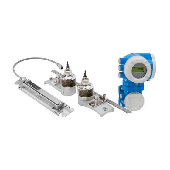
Endress+Hauser Proline Prosonic Flow P 500 Functional Safety Manual
Ultrasonic time-of-flight flowmeter hart
Hide thumbs
Also See for Proline Prosonic Flow P 500:
- Operating instructions manual (224 pages) ,
- Technical information (88 pages) ,
- Manual (80 pages)

Related Manuals for Endress+Hauser Proline Prosonic Flow P 500


Summary of Contents for Endress+Hauser Proline Prosonic Flow P 500
- Page 1 Products Solutions Services FY02647D/06/EN/01.21 71510592 2021-05-10 Valid as of version 01.01.zz (Device firmware) Functional Safety Manual Proline Prosonic Flow P 500 Ultrasonic time-of-flight flowmeter HART...
-
Page 3: Table Of Contents
Proline Prosonic Flow P 500 HART Table of contents Table of contents Manufacturer's Declaration ..4 Safety-related characteristic values ..5 About this document ... 7 Document function . -
Page 4: Manufacturer's Declaration
Manufacturer' s Declaration Proline Prosonic Flow P 500 HART Manufacturer's Declaration A0045946-EN Endress+Hauser... -
Page 5: Safety-Related Characteristic Values
Proline Prosonic Flow P 500 HART Manufacturer' s Declaration Safety-related characteristic values General Device designation and permitted 9P5B (Prosonic Flow P 500) versions Order code for "Output; input 1": Option BA "4-20mA HART" Order code for "Output; input 2": All options Order code for "Output;... - Page 6 Manufacturer' s Declaration Proline Prosonic Flow P 500 HART Hardware safety integrity Single-channel service SIL 2 capability SIL 3 capability (HFT = 0) Multi-channel service SIL 2 capability SIL 3 capability (HFT ≥ 1) FMEDA Safety function(s) Min., Max., Range...
-
Page 7: About This Document
The document is part of the Operating Instructions and serves as a reference for application- specific parameters and notes. • General information about functional safety: SIL • General information about SIL is available: In the Downloads area of the Endress+Hauser website: www.endress.com/SIL Using this document 2.2.1... -
Page 8: Supplementary Device Documentation
• W@M Device Viewer (www.endress.com/deviceviewer): Enter the serial number from nameplate • Endress+Hauser Operations App: Enter the serial number from the nameplate or scan the 2D matrix code (QR code) on the nameplate This Special Documentation is available: In the Download Area of the Endress+Hauser Internet site: www.endress.com →... -
Page 9: Permitted Device Types
Proline Prosonic Flow P 500 HART Permitted device types Measuring device Documentation code Prosonic Flow P 500 BA02025D Permitted device types The details pertaining to functional safety in this manual relate to the device versions listed below and are valid as of the specified software and hardware versions. Unless otherwise specified, all subsequent versions can also be used for safety functions. -
Page 10: Sil Label On The Nameplate
Safety function Proline Prosonic Flow P 500 HART Feature Designation Option selected Accessory mounted Accessory enclosed Firmware version Firmware with SIL capability, e.g. 01.01.zz (HART) Marking In devices with several outputs, only current output 1 (terminals 26 and 27) is suitable for safety functions. The other outputs can, if necessary, be connected for non-safety-oriented purposes. - Page 11 Proline Prosonic Flow P 500 HART Safety function In devices with several outputs, only current output 1 (terminals 26 and 27) is suitable for safety functions. The other outputs can, if necessary, be connected for non-safety-oriented purposes. The safety-related output signal is fed to a downstream automation system where it is monitored for the following: •...
-
Page 12: Restrictions For Use In Safety-Related
Safety function Proline Prosonic Flow P 500 HART I [mA] A0034924 Failure current ≥ 21 mA Measuring uncertainty Failure current ≤ 3.6 mA Restrictions for use in safety-related applications The measuring device must be used correctly for the specific application, taking into account the medium properties and ambient conditions. - Page 13 Proline Prosonic Flow P 500 HART Safety function 4.2.2 Useful lifetime of electric components The established failure rates of electrical components apply for a useful lifetime of 12 years as per IEC 61508-2: 2010, section 7.4.9.5, note 3. The device' s year of manufacture is coded in the first character of the serial number (→ table below).
- Page 14 • Process Operating Instructions and Technical Information Further information on the suitability of the measuring device for safety-related operation is available from your Endress+Hauser sales center. 4.2.4 Information on measured errors When the measured value is transmitted via the 4–20 mA current output, the measuring device' s relative measured error is made up of the contribution of the digitally determined measured value and the accuracy of the analog current output.
- Page 15 Proline Prosonic Flow P 500 HART Safety function The installation-specific measured error depends on the installation conditions on site, such as the nominal diameter, wall thickness, real pipe geometry or medium. The maximum installation-specific measured error is: Nominal diameter Installation-specific error limits...
- Page 16 Safety function Proline Prosonic Flow P 500 HART The current sound velocity of the medium must not deviate significantly from the sound velocity during installation. This deviation is a contributing factor in determining the installation status displayed in the device (Setup → Installation status → Installation status).
-
Page 17: Use In Protective Systems
Proline Prosonic Flow P 500 HART Use in protective systems Use in protective systems Device behavior during operation 5.1.1 Device behavior during power-up Once switched on, the device runs through a start-up phase. The current output is set to failure current during this time. This current is ≤ 3.6 mA in the initial seconds of this start-up phase. -
Page 18: Parameter Configuration For Safety
Use in protective systems Proline Prosonic Flow P 500 HART This behavior occurs in the case of the following diagnostic messages: 803 Current loop diagnostic message Parameter configuration for safety-related applications 5.2.1 Configuring the parameters of the measuring point The measuring point is calibrated via the operating interfaces. A wizard guides you systematically through all the submenus and parameters that have to be set for configuring the measuring device. - Page 19 Proline Prosonic Flow P 500 HART Use in protective systems Overview of the SIL mode The SIL mode enables the following steps: Makes sure that the preconditions are met. The measuring device checks whether the user has correctly configured a predefined set of parameters for the safety function.
- Page 20 Use in protective systems Proline Prosonic Flow P 500 HART NOTICE Once the SIL device has been locked, the process-related parameters are write protected, and thereby locked, for security reasons. It is still possible to read the parameters. When SIL locking is enabled, restrictions apply on all communication options, such as the service interface, HART protocol and WirelessHART protocol, local display and WLAN.
- Page 21 Proline Prosonic Flow P 500 HART Use in protective systems Setup Current output 1 Assign current output Volume flow A0025650-EN Diagnostics Simulation Assign Simulation process variable current output 1 A0021506-EN The diagnostic behavior is set in such a way that the measuring device is set to the safe state when an error occurs.
- Page 22 Use in protective systems Proline Prosonic Flow P 500 HART Expert System Diagnostic handling Diagnostic behavior Diagnostic no. Diagnostic no. 832, 833 Alarm A0044362-EN • 832 Electronics temperature too high • 833 Electronics temperature too low • 881 Sensor signal path...
- Page 23 Proline Prosonic Flow P 500 HART Use in protective systems Expert Sensor Sensor adjustment Sensor variable adjustment Volume flow Volume flow offset factor A0031496-EN Expert Sensor Process parameter Flow Flow damping override A0043256-EN Endress+Hauser...
- Page 24 Use in protective systems Proline Prosonic Flow P 500 HART To check that values are displayed correctly, the following string appears on the device display or operating tool: 0123456789+-. The user must confirm that the values are displayed correctly. The device displays the current settings for the following parameters one after...
- Page 25 Proline Prosonic Flow P 500 HART Use in protective systems NOTICE If the SIL confirmation sequence is aborted before the "End of sequence" message is displayed, the SIL device is not locked. The safety-oriented parameter settings have been made but the SIL device has not been locked.
-
Page 26: Proof Testing
Use in protective systems Proline Prosonic Flow P 500 HART Proof testing NOTICE The safety function is not guaranteed during a proof test. Nevertheless, process safety must be guaranteed during proof testing. ‣ The safety-related output signal 4 to 20 mA (output; input 1) may not be used for the protective system. - Page 27 Proline Prosonic Flow P 500 HART Use in protective systems Average probability of failure and mission time for a single-channel system: SIL2 - 1oo1 0.003 0.0025 0.002 0.0015 0.001 0.0005 A0042079 2 Options BA "4-20mA HART", CA "4-20mA HART Ex-i passive" and CC "4-20mA HART Ex-i active"...
- Page 28 Use in protective systems Proline Prosonic Flow P 500 HART 5.3.2 Proof testing the sensor subsystem If there are no operator-specific requirements for the proof test, the following alternative is available for testing the sensor subsystem depending on the "volume flow" measured variable used for the safety function.
- Page 29 Proline Prosonic Flow P 500 HART Use in protective systems 5.3.3 Device restart and testing of current output 1 • Part 1 - Device restart • Part 2 - Testing of current output 1 Preparation Byassing of safety function of process control system, to prevent accidental activation of the safety function.
- Page 30 Use in protective systems Proline Prosonic Flow P 500 HART Compare current at output 1 with this default value. Comparing the current values The current values can be compared using one of the following methods: • Measure the current of the DUT at the logic subsystem (process control system or safety- related PLC).
- Page 31 Proline Prosonic Flow P 500 HART Use in protective systems Document results of proof test in accordance with the safety management guidelines applicable to the system. NOTICE With the test sequences described, at least 48 % of the undetected dangerous failures can be detected.
- Page 32 Use in protective systems Proline Prosonic Flow P 500 HART Current output value Navigation Diagnostics → Simulation → Current output value (0355) Prerequisite In the Current output 1 to n simulation parameter, the On option is selected. Description Use this function to enter a current value for the simulation.
- Page 33 Proline Prosonic Flow P 500 HART Use in protective systems 5.3.4 Testing with a secondary standard Check measured value for liquid volume flow by comparing with a secondary standard Test sequence The measured values (3 to 5 measuring points) are checked with a secondary standard on an installed device (mobile calibration rig or calibrated reference device) or on a factory calibration rig following device removal.
- Page 34 Use in protective systems Proline Prosonic Flow P 500 HART 5.3.5 Testing with a secondary standard and testing of current output 1 • Part 1: Testing with a secondary standard • Part 2 - Testing of current output 1 Preparation Byassing of safety function of process control system, to prevent accidental activation of the safety function.
- Page 35 Proline Prosonic Flow P 500 HART Use in protective systems Performing the test For proof testing, use only the Current output simulation parameter (→ 31) and the Value current output parameter (→ 32), as these are the only parameters approved for testing the safety-related characteristics.
- Page 36 Use in protective systems Proline Prosonic Flow P 500 HART Evaluation of results - Part 2: Testing of current output 1 The amount of deviation between the measured current and the set point must not exceed the measured error specified for the safety function. The deviation should not exceed ±1 % / ±300 µA.
- Page 37 Proline Prosonic Flow P 500 HART Use in protective systems Additional Description information The desired simulation value is defined in the Value current output 1 to n parameter. Selection • Off Current simulation is switched off. The device is in normal measuring mode or another process variable is being simulated.
-
Page 38: Life Cycle
On completion of the verification, the SIL mode must be enabled again . The Heartbeat Verification application package is available as an order option and can be retrofitted on all measuring devices. Please contact your Endress+Hauser service or sales organization to retrofit the device. Life cycle Requirements for the personnel Installation 6.2.1... -
Page 39: Operation
Installation Instructions: see the Download Area at www.endress.com. The replaced component must be sent to Endress+Hauser for the purpose of fault analysis if the device has been operated in a protective system and a device error cannot be ruled out. In this case, always enclose the "Declaration of Hazardous Material and Decontamination"... -
Page 40: Decommissioning
Proline Prosonic Flow P 500 HART ‣ Modifications to devices with SIL capability onsite at the user' s plant are possible following approval by the Endress+Hauser manufacturing center. In this case, the modifications must be performed and documented by an Endress+Hauser service technician. ‣... -
Page 41: Verification Or Calibration
Proline Prosonic Flow P 500 HART Appendix 7.1.2 Description of use of protective system The measuring device can be used in protective systems to monitor the following (Min., Max. and range): Volume flow NOTICE The device must be correctly mounted to guarantee safe operation. -
Page 42: Version History
Appendix Proline Prosonic Flow P 500 HART The common cause factors β and β indicated below are minimum values for the device. These must be used when designing the sensor subsystem: • Minimum value β for homogeneously redundant use: 2 % •... - Page 44 *71510592* 71510592 www.addresses.endress.com...
Need help?
Do you have a question about the Proline Prosonic Flow P 500 and is the answer not in the manual?
Questions and answers