
Related Manuals for Endress+Hauser Proline Promag P 300 PROFIBUS DP


Summary of Contents for Endress+Hauser Proline Promag P 300 PROFIBUS DP
- Page 1 Products Solutions Services BA01853D/06/EN/01.18 71402605 2018-06-01 Valid as of version 01.00.zz (Device firmware) Operating Instructions Proline Promag P 300 PROFIBUS DP Electromagnetic flowmeter...
- Page 2 • The manufacturer reserves the right to modify technical data without prior notice. Your Endress+Hauser Sales Center will supply you with current information and updates to these instructions. Endress+Hauser...
-
Page 3: Table Of Contents
Proline Promag P 300 PROFIBUS DP Table of contents Table of contents About this document ....6 Installation ..... . . 21 Document function . - Page 4 Table of contents Proline Promag P 300 PROFIBUS DP 8.3.7 Calling the parameter directly ..60 10.6 Configuring the measuring device ..90 8.3.8 Calling up help text ....61 10.6.1 Defining the tag name .
- Page 5 13.2 Measuring and test equipment ... 182 13.3 Endress+Hauser services ....182 Repairs ......183 14.1 General notes .
-
Page 6: About This Document
About this document Proline Promag P 300 PROFIBUS DP About this document Document function These Operating Instructions contain all the information that is required in various phases of the life cycle of the device: from product identification, incoming acceptance and storage, to mounting, connection, operation and commissioning through to troubleshooting, maintenance and disposal. -
Page 7: Tool Symbols
Proline Promag P 300 PROFIBUS DP About this document Symbol Meaning Light emitting diode is on. Light emitting diode is flashing. 1.2.4 Tool symbols Symbol Meaning Flat blade screwdriver Allen key Open-ended wrench 1.2.5 Symbols for certain types of information... -
Page 8: Documentation
• W@M Device Viewer (www.endress.com/deviceviewer): Enter the serial number from nameplate • Endress+Hauser Operations App: Enter the serial number from the nameplate or scan the 2D matrix code (QR code) on the nameplate Detailed list of the individual documents along with the documentation code →... -
Page 9: Basic Safety Instructions
Proline Promag P 300 PROFIBUS DP Basic safety instructions Basic safety instructions Requirements for the personnel The personnel for installation, commissioning, diagnostics and maintenance must fulfill the following requirements: ‣ Trained, qualified specialists must have a relevant qualification for this specific function and task. -
Page 10: Workplace Safety
Verification for borderline cases: ‣ For special fluids and fluids for cleaning, Endress+Hauser is glad to provide assistance in verifying the corrosion resistance of fluid-wetted materials, but does not accept any warranty or liability as minute changes in the temperature, concentration or level of contamination in the process can alter the corrosion resistance properties. -
Page 11: Security
Proline Promag P 300 PROFIBUS DP Basic safety instructions It meets general safety standards and legal requirements. It also complies with the EU directives listed in the device-specific EU Declaration of Conformity. Endress+Hauser confirms this by affixing the CE mark to the device. IT security Our warranty is valid only if the device is installed and used as described in the Operating Instructions. -
Page 12: Infrastructure Mode
Basic safety instructions Proline Promag P 300 PROFIBUS DP • User-specific access code Protect write access to the device parameters via the local display, Web browser or operating tool (e.g. FieldCare, DeviceCare). Access authorization is clearly regulated through the use of a user-specific access code. -
Page 13: Access Via Service Interface (Cdi-Rj45)
Proline Promag P 300 PROFIBUS DP Basic safety instructions 2.7.4 Access via service interface (CDI-RJ45) The device can be connected to a network via the service interface (CDI-RJ45). Device- specific functions guarantee the secure operation of the device in a network. -
Page 14: Product Description
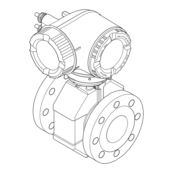
Product description Proline Promag P 300 PROFIBUS DP Product description The device consists of a transmitter and a sensor. The device is available as a compact version: The transmitter and sensor form a mechanical unit. Product design N ic te r e rg ö... -
Page 15: Incoming Acceptance And Product
Technical Documentation present? • If one of the conditions is not satisfied, contact your Endress+Hauser Sales Center. • Depending on the device version, the CD-ROM might not be part of the delivery! The Technical Documentation is available via the Internet or via the Endress+Hauser Operations App, see the "Product identification"... -
Page 16: Transmitter Nameplate
8 sections • The W@M Device Viewer: enter the serial number from the nameplate (www.endress.com/deviceviewer) • The Endress+Hauser Operations App: Enter the serial number from the nameplate or scan the 2-D matrix code (QR code) on the nameplate. 4.2.1... -
Page 17: Sensor Nameplate
Proline Promag P 300 PROFIBUS DP Incoming acceptance and product identification 4.2.2 Sensor nameplate Order code: Ser. no.: Ext. ord. cd.: Date: A0029205 3 Example of sensor nameplate Name of the sensor Manufacturing location Order code Serial number (ser. no.) Extended order code (Ext. -
Page 18: Symbols On Measuring Device
Incoming acceptance and product identification Proline Promag P 300 PROFIBUS DP 4.2.3 Symbols on measuring device Symbol Meaning WARNING! This symbol alerts you to a dangerous situation. Failure to avoid this situation can result in serious or fatal injury. Reference to documentation Refers to the corresponding device documentation. -
Page 19: Storage And Transport
Proline Promag P 300 PROFIBUS DP Storage and transport Storage and transport Storage conditions Observe the following notes for storage: ‣ Store in the original packaging to ensure protection from shock. ‣ Do not remove protective covers or protective caps installed on process connections. -
Page 20: Measuring Devices With Lifting Lugs
Storage and transport Proline Promag P 300 PROFIBUS DP 5.2.2 Measuring devices with lifting lugs CAUTION Special transportation instructions for devices with lifting lugs ‣ Only use the lifting lugs fitted on the device or flanges to transport the device. -
Page 21: Installation
Proline Promag P 300 PROFIBUS DP Installation Installation Installation conditions 6.1.1 Mounting position Mounting location A0029343 Preferably install the sensor in an ascending pipe, and ensure a sufficient distance to the next pipe elbow: h ≥ 2 × DN Installation in down pipes Install a siphon with a vent valve downstream of the sensor in down pipes whose length h ≥... - Page 22 Installation Proline Promag P 300 PROFIBUS DP For heavy sensors DN ≥ 350 (14") A0016276 Orientation The direction of the arrow on the sensor nameplate helps you to install the sensor according to the flow direction (direction of medium flow through the piping).
-
Page 23: Inlet And Outlet Runs
Proline Promag P 300 PROFIBUS DP Installation A0029344 EPD electrode for empty pipe detection Measuring electrodes for signal detection Reference electrode for potential equalization Measuring devices with tantalum or platinum electrodes can be ordered without an EPD electrode. In this case, empty pipe detection is performed via the measuring electrodes. -
Page 24: Thermal Insulation
Installation Proline Promag P 300 PROFIBUS DP System pressure A0028777 Never install the sensor on the pump suction side in order to avoid the risk of low pressure, and thus damage to the liner. Furthermore, install pulse dampers if reciprocating, diaphragm or peristaltic pumps are used. - Page 25 Proline Promag P 300 PROFIBUS DP Installation max. A0031216 Adapters Suitable adapters to DIN EN 545 (double-flange reducers) can be used to install the sensor in larger-diameter pipes. The resultant increase in the rate of flow improves measuring accuracy with very slow-moving fluids. The nomogram shown here can be used to calculate the pressure loss caused by reducers and expanders.
-
Page 26: Special Mounting Instructions
Installation Proline Promag P 300 PROFIBUS DP 6.1.3 Special mounting instructions Protective cover 280 (11.0) 255 (10.0) 146 (5.75) 134 (5.3) 12 (0.47) 30 (1.18) A0029553 Mounting the measuring device 6.2.1 Required tools For sensor For flanges and other process connections: Corresponding mounting tools 6.2.2... - Page 27 Proline Promag P 300 PROFIBUS DP Installation 5. Install the measuring device or turn the transmitter housing so that the cable entries do not point upwards. A0029263 Mounting the seals CAUTION An electrically conductive layer could form on the inside of the measuring tube! Risk of measuring signal short circuit.
- Page 28 Installation Proline Promag P 300 PROFIBUS DP Nominal Pressure rating Screws Flange thickness Max. screw tightening torque diameter [Nm] [mm] [bar] [mm] [mm] PTFE PN 40 8 × M24 PN 16 8 × M20 PN 40 8 × M24 PN 10 8 ×...
- Page 29 Proline Promag P 300 PROFIBUS DP Installation Nominal diameter Pressure rating Screws Flange thickness Nom. screw tightening torque [Nm] [mm] [bar] [mm] [mm] PTFE PN 16 20 × M27 PN 25 20 × M33 PN 10 20 × M24 PN 16 20 ×...
- Page 30 Installation Proline Promag P 300 PROFIBUS DP Screw tightening torques for JIS B2220, 10/20K Nominal diameter Pressure rating Screws Max. screw tightening torque [Nm] [mm] [bar] [mm] PTFE 4 × M16 4 × M16 4 × M16 – 4 × M16 –...
-
Page 31: Turning The Transmitter Housing
Proline Promag P 300 PROFIBUS DP Installation Screw tightening torques for AS 2129, Table E Nominal diameter Screws Max. screw tightening torque [Nm] [mm] [mm] PTFE 4 × M12 4 × M16 Screw tightening torques for AS 4087, PN 16... -
Page 32: Post-Installation Check
Installation Proline Promag P 300 PROFIBUS DP – – – 3 mm A0030035 1. Depending on the device version: Loosen the securing clamp of the connection compartment cover. 2. Unscrew the connection compartment cover. 3. Turn the display module to the desired position: max. 8 × 45° in each direction. -
Page 33: Electrical Connection
Proline Promag P 300 PROFIBUS DP Electrical connection Electrical connection NOTICE The measuring device does not have an internal circuit breaker. ‣ For this reason, assign the measuring device a switch or power-circuit breaker so that the power supply line can be easily disconnected from the mains. - Page 34 Electrical connection Proline Promag P 300 PROFIBUS DP Signal damping Max. 9 dB over the entire length of the cable cross-section Shield Copper braided shielding or braided shielding with foil shield. When grounding the cable shield, observe the grounding concept of the plant.
- Page 35 Proline Promag P 300 PROFIBUS DP Electrical connection Standard cable - customer-specific cable No cable is supplied, and it must be provided by the customer (up to max. 300 m (1 000 ft)) for the following order option: Order code for DKX001: Order code 040 for "Cable", option 1 "None, provided by customer, max 300 m"...
-
Page 36: Terminal Assignment
Electrical connection Proline Promag P 300 PROFIBUS DP 7.1.3 Terminal assignment Transmitter: supply voltage, input/outputs The terminal assignment of the inputs and outputs depends on the individual order version of the device. The device-specific terminal assignment is documented on an adhesive label in the terminal cover. -
Page 37: Preparing The Measuring Device
Proline Promag P 300 PROFIBUS DP Electrical connection A0036639 Controller (e.g. PLC) Cable shield T-box Measuring device Local grounding Bus terminator Potential matching line 7.1.5 Preparing the measuring device NOTICE Insufficient sealing of the housing! Operational reliability of the measuring device could be compromised. -
Page 38: Connecting The Transmitter
Electrical connection Proline Promag P 300 PROFIBUS DP 7.2.1 Connecting the transmitter A0026781 Terminal connection for supply voltage Terminal connection for signal transmission, input/output Terminal connection for signal transmission, input/output or terminal connection for network connection via service interface (CDI-RJ45); optional: connection for external WLAN antenna or remote display and... - Page 39 Proline Promag P 300 PROFIBUS DP Electrical connection 10 (0.4) mm (in) – A0029815 7. Push the cable through the cable entry . To ensure tight sealing, do not remove the sealing ring from the cable entry. 8. Strip the cable and cable ends. In the case of stranded cables, also fit ferrules.
- Page 40 Electrical connection Proline Promag P 300 PROFIBUS DP Removing a cable 3 (0.12) A0029598 6 Engineering unit mm (in) 1. To remove a cable from the terminal, use a flat-blade screwdriver to push the slot between the two terminal holes 2.
-
Page 41: Connecting The Remote Display And Operating Module Dkx001
Proline Promag P 300 PROFIBUS DP Electrical connection 7.2.2 Connecting the remote display and operating module DKX001 The remote display and operating module DKX001 is available as an optional extra → 185. • The measuring device is always supplied with a dummy cover when the remote display and operating module DKX001 is ordered directly with the measuring device. -
Page 42: Connection Example In Special Situations
Electrical connection Proline Promag P 300 PROFIBUS DP 7.3.3 Connection example in special situations Unlined and ungrounded metal pipe This connection method also applies in situations where: • The customary potential equalization is not used • Equalizing currents are present... -
Page 43: Special Connection Instructions
Proline Promag P 300 PROFIBUS DP Electrical connection Ground cable Copper wire, at least 6 mm (0.0093 in – A0029340 Prerequisite: The sensor is installed in the pipe in a way that provides electrical insulation. 1. Connect the two flanges of the pipe to one another via a ground cable. -
Page 44: Current Output 4-20 Ma
Electrical connection Proline Promag P 300 PROFIBUS DP Current output 4-20 mA 4...20 mA A0028758 11 Connection example for 4-20 mA current output (active) Automation system with current input (e.g. PLC) Analog display unit: observe maximum load Transmitter 4...20 mA A0028759 ... -
Page 45: Switch Output
Proline Promag P 300 PROFIBUS DP Electrical connection Switch output A0028760 14 Connection example for switch output (passive) Automation system with switch input (e.g. PLC) Power supply Transmitter: Observe input values → 191 Relay output A0028760 15 Connection example for relay output (passive) Automation system with relay input (e.g. -
Page 46: Hardware Settings
Electrical connection Proline Promag P 300 PROFIBUS DP Status input A0028764 17 Connection example for status input Automation system with status output (e.g. PLC) Power supply Transmitter Hardware settings 7.5.1 Setting the device address The address must always be configured for a PROFIBUS DP/PA device. The valid address range is between 1 and 126. -
Page 47: Software Addressing
Proline Promag P 300 PROFIBUS DP Electrical connection Software addressing ‣ To switch addressing from hardware addressing to software addressing: set DIP switch No. 4 to Off. The device address configured in the Device address parameter (→ 94) takes effect after 10 seconds. -
Page 48: Ensuring The Degree Of Protection
Electrical connection Proline Promag P 300 PROFIBUS DP 3. Set DIP switch No. 2 on the I/O electronics module from OFF → ON. 4. Reverse the removal procedure to reassemble the transmitter. 5. Reconnect the device to the power supply. -
Page 49: Operation Options
Proline Promag P 300 PROFIBUS DP Operation options Operation options Overview of operation options A0034513 Local operation via display module Computer with Web browser (e.g. Internet Explorer) or with operating tool (e.g. FieldCare, DeviceCare, AMS Device Manager, SIMATIC PDM) Field Xpert SFX350 or SFX370... -
Page 50: Structure And Function Of The Operating Menu
Operation options Proline Promag P 300 PROFIBUS DP Structure and function of the operating menu 8.2.1 Structure of the operating menu For an overview of the operating menu for experts: "Description of Device Parameters" document supplied with the device→ 213... -
Page 51: Operating Philosophy
Proline Promag P 300 PROFIBUS DP Operation options 8.2.2 Operating philosophy The individual parts of the operating menu are assigned to certain user roles (operator, maintenance etc.). Each user role contains typical tasks within the device lifecycle. Menu/parameter User role and tasks... -
Page 52: Display
Operation options Proline Promag P 300 PROFIBUS DP Menu/parameter User role and tasks Content/meaning Expert function-oriented Tasks that require detailed Contains all the parameters of the device and makes it possible to access knowledge of the function of the these parameters directly using an access code. The structure of this menu is... -
Page 53: Display Area
Proline Promag P 300 PROFIBUS DP Operation options Display area In the display area, each measured value is prefaced by certain symbol types for further description: Measured variable Measurement channel Diagnostic behavior number ↓ ↓ ↓ Example Appears only if a diagnostics event is present for this measured variable. -
Page 54: Navigation View
Operation options Proline Promag P 300 PROFIBUS DP 8.3.2 Navigation view In the submenu In the wizard /../Operation 0091-1 /../Curr. output 1 Access stat.disp Assign curr. Operator Volume flow Locking status Display A0013993-EN A0016327-EN Navigation view Navigation path to current position... - Page 55 Proline Promag P 300 PROFIBUS DP Operation options Display area Menus Symbol Meaning Operation Appears: • In the menu next to the "Operation" selection • At the left in the navigation path in the Operation menu Setup Appears: • In the menu next to the "Setup" selection •...
-
Page 56: Editing View
Operation options Proline Promag P 300 PROFIBUS DP 8.3.3 Editing view Numeric editor +0.000 Xx – A0034250 19 For entering values in parameters (e.g. limit values) Entry display area Input screen Confirm, delete or reject entry Operating elements Text editor... - Page 57 Proline Promag P 300 PROFIBUS DP Operation options Operating key(s) Meaning Enter key • Press the key briefly: confirm your selection. • Press the key for 2 s: confirm the entry. Escape key combination (press keys simultaneously) Close the editing view without accepting the changes.
-
Page 58: Operating Elements
Operation options Proline Promag P 300 PROFIBUS DP 8.3.4 Operating elements Operating key(s) Meaning Minus key In a menu, submenu Moves the selection bar upwards in a picklist. With a Wizard Confirms the parameter value and goes to the previous parameter. - Page 59 Proline Promag P 300 PROFIBUS DP Operation options Calling up and closing the context menu The user is in the operational display. 1. Press the and keys for longer than 3 seconds. The context menu opens. XXXXXXXXXX Setup Conf.backup...
-
Page 60: Navigating And Selecting From List
Operation options Proline Promag P 300 PROFIBUS DP 8.3.6 Navigating and selecting from list Different operating elements are used to navigate through the operating menu. The navigation path is displayed on the left in the header. Icons are displayed in front of the individual menus. -
Page 61: Calling Up Help Text
Proline Promag P 300 PROFIBUS DP Operation options The direct access code consists of a 5-digit number (at maximum) and the channel number, which identifies the channel of a process variable: e.g. 00914-2. In the navigation view, this appears on the right-hand side in the header of the selected parameter. -
Page 62: User Roles And Related Access Authorization
Operation options Proline Promag P 300 PROFIBUS DP Ent. access code Invalid or out of range input value Min:0 Max:9999 A0014049-EN For a description of the editing view - consisting of the text editor and numeric editor - with symbols → 56, for a description of the operating elements → 58 8.3.10... -
Page 63: Enabling And Disabling The Keypad
Proline Promag P 300 PROFIBUS DP Operation options 2. Enter the access code. The -symbol in front of the parameters disappears; all previously write- protected parameters are now re-enabled. 8.3.12 Enabling and disabling the keypad lock The keypad lock makes it possible to block access to the entire operating menu via local operation. -
Page 64: Prerequisites
Operation options Proline Promag P 300 PROFIBUS DP 8.4.2 Prerequisites Computer hardware Hardware Interface CDI-RJ45 WLAN Interface The computer must have an RJ45 The operating unit must have a interface. WLAN interface. Connection Standard Ethernet cable with RJ45 Connection via Wireless LAN. -
Page 65: Establishing A Connection
Proline Promag P 300 PROFIBUS DP Operation options Measuring device: Via CDI-RJ45 service interface Device CDI-RJ45 service interface Measuring device The measuring device has an RJ45 interface. Web server Web server must be enabled; factory setting: ON For information on enabling the Web server → 69... - Page 66 Operation options Proline Promag P 300 PROFIBUS DP Via WLAN interface Configuring the Internet protocol of the mobile terminal NOTICE If the WLAN connection is lost during the configuration, settings made may be lost. ‣ Make sure that the WLAN connection is not disconnected while configuring the device.
-
Page 67: Logging On
Proline Promag P 300 PROFIBUS DP Operation options 2. Enter the IP address of the Web server in the address line of the Web browser: 192.168.1.212 The login page appears. 2 3 4 A0029417 Picture of device Device name... -
Page 68: User Interface
Operation options Proline Promag P 300 PROFIBUS DP 8.4.5 User interface A0029418 Function row Local display language Navigation area Header The following information appears in the header: • Device name • Device tag • Device status with status signal → 148 •... -
Page 69: Disabling The Web Server
Proline Promag P 300 PROFIBUS DP Operation options Navigation area If a function is selected in the function bar, the submenus of the function open in the navigation area. The user can now navigate through the menu structure. Working area... -
Page 70: Access To The Operating Menu Via The Operating Tool
Operation options Proline Promag P 300 PROFIBUS DP Access to the operating menu via the operating tool The structure of the operating menu in the operating tools is the same as for operation via the local display. 8.5.1 Connecting the operating tool Via PROFIBUS DP network This communication interface is available in device versions with PROFIBUS DP. - Page 71 Proline Promag P 300 PROFIBUS DP Operation options A0027563 23 Connection via service interface (CDI-RJ45) Computer with Web browser (e.g. Microsoft Internet Explorer, Microsoft Edge) for accessing the integrated device Web server or with "FieldCare", "DeviceCare" operating tool with COM DTM "CDI Communication TCP/IP"...
-
Page 72: Fieldcare
FieldCare Function scope FDT-based plant asset management tool from Endress+Hauser. It can configure all smart field devices in a system and helps you manage them. By using the status information, it is also a simple but effective way of checking their status and condition. - Page 73 Proline Promag P 300 PROFIBUS DP Operation options Typical functions: • Configuring parameters of transmitters • Loading and saving device data (upload/download) • Documentation of the measuring point • Visualization of the measured value memory (line recorder) and event logbook...
-
Page 74: Devicecare
DeviceCare Function scope Tool to connect and configure Endress+Hauser field devices. The fastest way to configure Endress+Hauser field devices is with the dedicated "DeviceCare" tool. Together with the device type managers (DTMs) it presents a convenient, comprehensive solution. For details, see Innovation Brochure IN01047S Source for device description files See information →... -
Page 75: System Integration
Proline Promag P 300 PROFIBUS DP System integration System integration Overview of device description files 9.1.1 Current version data for the device Firmware version 01.00.zz • On the title page of the Operating instructions • On the transmitter nameplate • Firmware version Diagnostics →... -
Page 76: Manufacturer-Specific Gsd
System integration Proline Promag P 300 PROFIBUS DP 9.2.1 Manufacturer-specific GSD This GSD guarantees the unrestricted functionality of the measuring device. Device-specific process parameters and functions are therefore available. Manufacturer-specific GSD ID number File name PROFIBUS DP 0x1570 EH3x1570.gsd The fact that the manufacturer-specific GSD should be used is specified in the Ident number selector parameter by selecting the Manufacturer option. -
Page 77: Manual Setting
Proline Promag P 300 PROFIBUS DP System integration makes the same input and output data and measured value status information available for cyclic data exchange. Automatic identification is set in the Ident number selector parameter using the Automatic mode option (factory setting). -
Page 78: Using The Gsd Modules Of The Previous Model
System integration Proline Promag P 300 PROFIBUS DP Using the GSD modules of the previous model In the compatibility mode, all the modules already configured in the automation system are generally supported during cyclic data transmission. However, Promag 300 does not perform further processing for the following modules, i.e. - Page 79 Proline Promag P 300 PROFIBUS DP System integration Control variable Function Support 0 → 55 Relay output 2: ON Yes, terminals 22/23 (I/O 3) 0 → 56 Relay output 2: OFF 0 → 30 to 46 Additional functions: Batching Endress+Hauser...
-
Page 80: Cyclic Data Transmission
System integration Proline Promag P 300 PROFIBUS DP Cyclic data transmission Cyclic data transmission when using the device master file (GSD). 9.5.1 Block model The block model shows which input and output data the measuring device makes available for cyclic data exchange. Cyclic data exchange takes place with a PROFIBUS master (Class 1), e.g. -
Page 81: Ai Module (Analog Input)
Proline Promag P 300 PROFIBUS DP System integration AI module (Analog Input) Transmit an input variable from the measuring device to the PROFIBUS master (Class 1). The selected input variable, along with the status, is cyclically transmitted to the PROFIBUS Master (Class 1) via the AI module. The input variable is depicted in the first four bytes in the form of a floating point number as per the IEEE 754 standard. - Page 82 System integration Proline Promag P 300 PROFIBUS DP Selection: totalizer value Input variable Volume flow Mass flow Corrected volume flow Factory setting Function block Factory setting: TOTAL Totalizer 1, 2 and 3 Volume flow Data structure Input data of TOTAL...
- Page 83 Proline Promag P 300 PROFIBUS DP System integration SETTOT_MODETOT_TOTAL module The module combination consists of the SETTOT, MODETOT and TOTAL functions: • SETTOT: Control the totalizers via the PROFIBUS master. • MODETOT: Configure the totalizers via the PROFIBUS master. • TOTAL: Transmit totalizer value, along with the status, to the PROFIBUS master.
- Page 84 System integration Proline Promag P 300 PROFIBUS DP Assigned compensation values A compensation value is permanently assigned to the individual Analog Output blocks. Function block Compensation value AO 1 External temperature AO 2 External density The compensation values must be transmitted to the device in the SI basic unit The selection is made via: Expert →...
-
Page 85: Empty_Module Module
Proline Promag P 300 PROFIBUS DP System integration Data structure Input data of Discrete Input Byte 1 Byte 2 Discrete Status DO module (Discrete Output) Transmit discrete output values from the PROFIBUS master (Class 1) to the measuring device. Discrete output values are used by the PROFIBUS master (Class 1) to enable and disable device functions. -
Page 86: Address Shifting Configuration
System integration Proline Promag P 300 PROFIBUS DP Address shifting configuration 9.6.1 Function description The field device also makes acyclic communication services available in addition to cyclic communication. This enables automation systems (PLCs), central engineering stations and asset management systems to exchange data acyclically with the field device. This mode of communication is typically used to configure the field device. -
Page 87: Configuring Address Shifting
1001 : °C 1002 : °F 1000 : K 1003 : °R For more information on the "slot/index table", please contact the Endress+Hauser Sales Center. 9.6.4 Accessing data via PROFIBUS DP The PROFIBUS master uses the indexes 230 to 245 in slot 0 to access the address shifting data area. - Page 88 System integration Proline Promag P 300 PROFIBUS DP parameter via address shifting, the master can read out the current volume flow measured value in slot 0 and index 230. The data type (integer/float) and data access (read/write) depend on the parameter entered in the configuration area.
-
Page 89: Commissioning
Proline Promag P 300 PROFIBUS DP Commissioning Commissioning 10.1 Function check Before commissioning the measuring device: ‣ Make sure that the post-installation and post-connection checks have been performed. • "Post-installation check" checklist→ 32 • "Post-connection check" checklist → 48 10.2... -
Page 90: Configuring The Measuring Device
Commissioning Proline Promag P 300 PROFIBUS DP X X X X X X X 20.50 Main menu 0104-1 Display language English Operation Setup Display language 0104-1 English à Deutsch Español Français Display language 0104-1 à English Deutsch Español Français Hauptmenü... -
Page 91: Defining The Tag Name
Proline Promag P 300 PROFIBUS DP Commissioning Navigation "Setup" menu Setup → 92 Device tag ‣ → 92 System units ‣ Communication → 93 ‣ Analog inputs → 95 ‣ I/O configuration → 95 ‣... -
Page 92: Setting The System Units
Commissioning Proline Promag P 300 PROFIBUS DP Navigation "Setup" menu → Device tag Parameter overview with brief description Parameter Description User entry Factory setting Device tag Enter the name for the measuring point. Max. 32 characters, such as Promag300/500DP letters, numbers or special characters (e.g. -
Page 93: Interface
Proline Promag P 300 PROFIBUS DP Commissioning Parameter Prerequisite Description Selection Factory setting Conductivity unit The On option is selected in Select conductivity unit. Unit choose list µS/cm the Conductivity Effect measurement parameter The selected unit applies for: parameter. Simulation process variable Temperature unit –... -
Page 94: Parameter Overview With Brief Description
Commissioning Proline Promag P 300 PROFIBUS DP Parameter overview with brief description Parameter Description User entry Factory setting Device address Enter device address. 0 to 126 Endress+Hauser... -
Page 95: Configuring The Analog Inputs
Proline Promag P 300 PROFIBUS DP Commissioning 10.6.4 Configuring the analog inputs The Analog inputs submenu guides the user systematically to the individual Analog input 1 to n submenu. From here you get to the parameters of the individual analog input. -
Page 96: Configuring The Current Input
Commissioning Proline Promag P 300 PROFIBUS DP Navigation "Setup" menu → I/O configuration ‣ I/O configuration → 96 I/O module 1 to n terminal numbers → 96 I/O module 1 to n information I/O module 1 to n type →... -
Page 97: Configuring The Status Input
Proline Promag P 300 PROFIBUS DP Commissioning Signal mode → 97 0/4 mA value → 97 20 mA value → 97 Current span → 97 → 97 Failure mode Failure value → 97 Parameter overview with brief description... -
Page 98: Configuring The Current Output
Commissioning Proline Promag P 300 PROFIBUS DP Terminal number → 98 Active level → 98 Terminal number → 98 Response time status input → 98 → 98 Terminal number Parameter overview with brief description Parameter Description User interface / Selection / ... - Page 99 Proline Promag P 300 PROFIBUS DP Commissioning Fixed current → 99 Damping output 1 to n → 99 Failure mode → 100 Failure current → 100 Parameter overview with brief description Parameter Prerequisite Description User interface / ...
- Page 100 Commissioning Proline Promag P 300 PROFIBUS DP Parameter Prerequisite Description User interface / Factory setting Selection / User entry Failure mode A process variable is selected Define output behavior in • Min. Max. in the Assign current output alarm condition. • Max. parameter (→ 99) and one •...
-
Page 101: Configuring The Pulse/Frequency
Proline Promag P 300 PROFIBUS DP Commissioning 10.6.9 Configuring the pulse/frequency/switch output The Pulse/frequency/switch output wizard guides you systematically through all the parameters that can be set for configuring the selected output type. Navigation "Setup" menu → Advanced setup → Pulse/frequency/switch output ‣... - Page 102 Commissioning Proline Promag P 300 PROFIBUS DP Parameter overview with brief description Parameter Prerequisite Description Selection / User Factory setting interface / User entry Operating mode – Define the output as a pulse, • Pulse Pulse frequency or switch output. • Frequency • Switch Terminal number –...
- Page 103 Proline Promag P 300 PROFIBUS DP Commissioning Maximum frequency value → 103 Measuring value at minimum → 103 frequency Measuring value at maximum → 104 frequency → 104 Failure mode → 104 Failure frequency Invert output signal →...
- Page 104 Commissioning Proline Promag P 300 PROFIBUS DP Parameter Prerequisite Description Selection / User Factory setting interface / User entry Measuring value at maximum The Frequency option is Enter measured value for Signed floating-point Depends on country frequency selected in the Operating maximum frequency. number and nominal mode parameter (→...
- Page 105 Proline Promag P 300 PROFIBUS DP Commissioning Configuring the switch output Navigation "Setup" menu → Pulse/frequency/switch output ‣ Pulse/frequency/switch output 1 to n Operating mode → 105 Terminal number → 105 Signal mode → 105 → 106...
- Page 106 Commissioning Proline Promag P 300 PROFIBUS DP Parameter Prerequisite Description Selection / User Factory setting interface / User entry Switch output function The Switch option is selected Select function for switch • Off in the Operating mode output. • On parameter. • Diagnostic behavior •...
-
Page 107: 10.6.10 Configuring The Relay Output
Proline Promag P 300 PROFIBUS DP Commissioning Parameter Prerequisite Description Selection / User Factory setting interface / User entry Switch-off delay • The Switch option is Define delay for the switch-off 0.0 to 100.0 s 0.0 s selected in the Operating of status output. - Page 108 Commissioning Proline Promag P 300 PROFIBUS DP Parameter overview with brief description Parameter Prerequisite Description Selection / User Factory setting interface / User entry Relay output function – Select the function for the • Closed Closed relay output. • Open • Diagnostic behavior • Limit •...
-
Page 109: 10.6.11 Configuring The Local Display
Proline Promag P 300 PROFIBUS DP Commissioning 10.6.11 Configuring the local display The Display wizard guides you systematically through all the parameters that can configured for configuring the local display. Navigation "Setup" menu → Display ‣ Display → 109 Format display →... - Page 110 Commissioning Proline Promag P 300 PROFIBUS DP Parameter Prerequisite Description Selection / User Factory setting entry 100% bargraph value 1 A local display is provided. Enter 100% value for bar Signed floating-point Depends on country graph display. number and nominal diameter Value 2 display A local display is provided.
-
Page 111: 10.6.12 Configuring The Low Flow Cut Off
Proline Promag P 300 PROFIBUS DP Commissioning Parameter Prerequisite Description Selection / User Factory setting entry 100% bargraph value 3 A selection was made in the Enter 100% value for bar Signed floating-point Value 3 display parameter. graph display. number Value 4 display A local display is provided. - Page 112 Commissioning Proline Promag P 300 PROFIBUS DP Parameter Prerequisite Description Selection / User Factory setting entry Off value low flow cutoff A process variable is selected Enter off value for low flow cut 0 to 100.0 % 50 % in the Assign process variable off.
-
Page 113: 10.6.13 Configuring Empty Pipe Detection
Proline Promag P 300 PROFIBUS DP Commissioning 10.6.13 Configuring empty pipe detection The Empty pipe detection submenu contains parameters that must be configured for the configuration of empty pipe detection. Navigation "Setup" menu → Empty pipe detection ‣ Empty pipe detection →... -
Page 114: Advanced Settings
Commissioning Proline Promag P 300 PROFIBUS DP 10.7 Advanced settings The Advanced setup submenu together with its submenus contains parameters for specific settings. Navigation to the "Advanced setup" submenu X X X X X X X 20.50 0104-1 Main menu... -
Page 115: Carrying Out A Sensor Adjustment
Proline Promag P 300 PROFIBUS DP Commissioning ‣ WLAN settings ‣ Heartbeat setup ‣ Configuration backup → 122 ‣ Administration → 124 10.7.1 Carrying out a sensor adjustment The Sensor adjustment submenu contains parameters that pertain to the functionality of the sensor. - Page 116 Commissioning Proline Promag P 300 PROFIBUS DP Parameter overview with brief description Parameter Description Selection Factory setting Assign process variable Select process variable for totalizer. • Volume flow Volume flow • Mass flow • Corrected volume flow Unit totalizer Select the unit for the process variable of the...
-
Page 117: Carrying Out Additional Display Configurations
Proline Promag P 300 PROFIBUS DP Commissioning 10.7.3 Carrying out additional display configurations In the Display submenu you can set all the parameters associated with the configuration of the local display. Navigation "Setup" menu → Advanced setup → Display ‣... - Page 118 Commissioning Proline Promag P 300 PROFIBUS DP Parameter overview with brief description Parameter Prerequisite Description Selection / User Factory setting entry Format display A local display is provided. Select how measured values • 1 value, max. size 1 value, max. size are shown on the display.
- Page 119 Proline Promag P 300 PROFIBUS DP Commissioning Parameter Prerequisite Description Selection / User Factory setting entry Value 3 display A local display is provided. Select the measured value that • None None is shown on the local display. • Volume flow • Mass flow •...
-
Page 120: Performing Electrode Cleaning
Commissioning Proline Promag P 300 PROFIBUS DP Parameter Prerequisite Description Selection / User Factory setting entry Display language A local display is provided. Set display language. • English English • Deutsch (alternatively, the • Français ordered language is • Español preset in the device) •... -
Page 121: Wlan Configuration
Proline Promag P 300 PROFIBUS DP Commissioning Navigation "Setup" menu → Advanced setup → Electrode cleaning circuit ‣ Electrode cleaning circuit → 121 Electrode cleaning circuit → 121 ECC duration ECC recovery time → 121 ECC cleaning cycle →... -
Page 122: Configuration Management
Commissioning Proline Promag P 300 PROFIBUS DP Security type → 122 WLAN passphrase → 122 Assign SSID name → 122 SSID name → 122 → 122 Apply changes Parameter overview with brief description Parameter Prerequisite Description User entry / ... -
Page 123: Function Scope Of The "Configuration Management" Parameter
Proline Promag P 300 PROFIBUS DP Commissioning Navigation "Setup" menu → Advanced setup → Configuration backup ‣ Configuration backup → 123 Operating time → 123 Last backup Configuration management → 123 Backup state → 123 Comparison result →... -
Page 124: Using Parameters For Device Administration
Commissioning Proline Promag P 300 PROFIBUS DP Options Description Compare The device configuration saved in the device memory is compared with the current device configuration of the HistoROM backup. Clear backup data The backup copy of the device configuration is deleted from the memory of the device. -
Page 125: Simulation
Proline Promag P 300 PROFIBUS DP Commissioning Using the parameter to reset the access code Navigation "Setup" menu → Advanced setup → Administration → Reset access code ‣ Reset access code Operating time → 125 Reset access code → 125... - Page 126 Commissioning Proline Promag P 300 PROFIBUS DP Process variable value → 126 Status input simulation → 127 Input signal level → 127 Current input 1 to n simulation → 127 → 127 Value current input 1 to n Current output 1 to n simulation →...
- Page 127 Proline Promag P 300 PROFIBUS DP Commissioning Parameter Prerequisite Description Selection / User Factory setting entry / User interface Status input simulation – Switch simulation of the status • Off input on and off. • On Input signal level In the Status input simulation Select the signal level for the •...
-
Page 128: Protecting Settings From Unauthorized Access
Commissioning Proline Promag P 300 PROFIBUS DP Parameter Prerequisite Description Selection / User Factory setting entry / User interface Diagnostic event category – Select a diagnostic event • Sensor Process category. • Electronics • Configuration • Process Diagnostic event simulation – Select a diagnostic event to •... -
Page 129: Write Protection Via Write Protection Switch
Via Web browser, FieldCare, DeviceCare (via CDI-RJ45 service interface), fieldbus For a reset code, contact your Endress+Hauser service organization. 1. Navigate to the Reset access code parameter (→ 125). 2. Enter the reset code. - Page 130 Commissioning Proline Promag P 300 PROFIBUS DP A0029630 Setting the write protection (WP) switch on the main electronics module to the ON position enables hardware write protection. In the Locking status parameter the Hardware locked option is displayed → 131. In addition, on the local display the -symbol appears in front of the parameters in the header of the operational display and in the navigation view.
-
Page 131: Operation
Proline Promag P 300 PROFIBUS DP Operation Operation 11.1 Reading the device locking status Device active write protection: Locking status parameter Operation → Locking status Function scope of the "Locking status" parameter Options Description None The access status displayed in the Access status parameter applies → 62. Only appears on local display. -
Page 132: Process Variables" Submenu
Operation Proline Promag P 300 PROFIBUS DP 11.4.1 "Process variables" submenu The Process variables submenu contains all the parameters needed to display the current measured values for each process variable. Navigation "Diagnostics" menu → Measured values → Process variables ‣... -
Page 133: Totalizer
Proline Promag P 300 PROFIBUS DP Operation Parameter Prerequisite Description User interface Corrected conductivity One of the following conditions is met: Displays the conductivity currently Positive floating-point • Order code for "Sensor option", option corrected. number CI "Medium temperature Dependency measurement"... -
Page 134: Input Values" Submenu
Operation Proline Promag P 300 PROFIBUS DP Parameter overview with brief description Parameter Prerequisite Description Selection / User Factory setting entry / User interface Assign process variable – Select process variable for • Volume flow Volume flow totalizer. • Mass flow • Corrected volume... -
Page 135: Output Values
Proline Promag P 300 PROFIBUS DP Operation Parameter overview with brief description Parameter Description User interface Measured values 1 to n Displays the current input value. Signed floating-point number Measured current 1 to n Displays the current value of the current input. - Page 136 Operation Proline Promag P 300 PROFIBUS DP Navigation "Diagnostics" menu → Measured values → Output values → Value current output 1 to n ‣ Current output 1 to n → 136 Output current 1 to n → 136...
-
Page 137: Adapting The Measuring Device To The Process Conditions
Proline Promag P 300 PROFIBUS DP Operation Navigation "Diagnostics" menu → Measured values → Output values → Relay output 1 to n ‣ Relay output 1 to n → 137 Switch status → 137 Switch cycles Max. switch cycles number →... -
Page 138: Showing Data Logging
Operation Proline Promag P 300 PROFIBUS DP Preset value 1 to n → 138 Reset all totalizers → 138 Parameter overview with brief description Parameter Description Selection / User entry Factory setting Control Totalizer 1 to n Control totalizer value. - Page 139 Proline Promag P 300 PROFIBUS DP Operation Assign channel 3 → 140 Assign channel 4 → 140 Logging interval → 140 Clear logging data → 140 → 140 Data logging Logging delay → 140 Data logging control →...
- Page 140 Operation Proline Promag P 300 PROFIBUS DP Parameter Prerequisite Description Selection / User Factory setting entry / User interface Assign channel 3 The Extended HistoROM Assign process variable to Picklist, see Assign application package is logging channel. channel 1 parameter available. (→ 139) ...
-
Page 141: Diagnostics And Troubleshooting
Proline Promag P 300 PROFIBUS DP Diagnostics and troubleshooting Diagnostics and troubleshooting 12.1 General troubleshooting For local display Error Possible causes Solution Local display dark and no output Supply voltage does not match the Apply the correct supply voltage signals value indicated on the nameplate. - Page 142 Diagnostics and troubleshooting Proline Promag P 300 PROFIBUS DP For access Error Possible causes Solution No write access to parameters Hardware write protection enabled Set the write protection switch on main electronics module to the OFF position → 129.
- Page 143 Proline Promag P 300 PROFIBUS DP Diagnostics and troubleshooting Error Possible causes Solution No or incomplete display of • JavaScript not enabled 1. Enable JavaScript. contents in the Web browser • JavaScript cannot be enabled 2. Enter http://XXX.XXX.X.XXX/ basic.html as the IP address.
-
Page 144: Diagnostic Information Via Light Emitting Diodes
Diagnostics and troubleshooting Proline Promag P 300 PROFIBUS DP 12.2 Diagnostic information via light emitting diodes 12.2.1 Transmitter Different LEDs in the transmitter provide information on the device status. 1 2 3 4 5 A0029629 Supply voltage Device status Not used... -
Page 145: Diagnostic Information On Local Display
Proline Promag P 300 PROFIBUS DP Diagnostics and troubleshooting 12.3 Diagnostic information on local display 12.3.1 Diagnostic message Faults detected by the self-monitoring system of the measuring device are displayed as a diagnostic message in alternation with the operational display. -
Page 146: Diagnostic Information
Diagnostics and troubleshooting Proline Promag P 300 PROFIBUS DP Diagnostic behavior Symbol Meaning Alarm • Measurement is interrupted. • Signal outputs and totalizers assume the defined alarm condition. • A diagnostic message is generated. Warning Measurement is resumed. The signal outputs and totalizers are not affected. A diagnostic message is generated. -
Page 147: Calling Up Remedial Measures
Proline Promag P 300 PROFIBUS DP Diagnostics and troubleshooting 12.3.2 Calling up remedial measures X X X X X X X X X X X X X X 20.50 S801 Supply voltage Menu Diagnostic list Diagnostics 1 S801 Supply voltage... -
Page 148: Calling Up Remedy Information
Diagnostics and troubleshooting Proline Promag P 300 PROFIBUS DP A0031056 Status area with status signal Diagnostic information→ 146 Remedy information with Service ID In addition, diagnostic events which have occurred can be shown in the Diagnostics menu: • Via parameter •... -
Page 149: Calling Up Remedy Information
Proline Promag P 300 PROFIBUS DP Diagnostics and troubleshooting Xxxxxx/…/…/ Device name: Xxxxxxx Mass flow: kg/h 12.34 Device tag: Xxxxxxx Volume flow: 12.34 m /h ³ Status signal: Function check (C) Xxxxxx Diagnostics 1: C485 Simu... Remedy information: Deactivate... Failure (F) -
Page 150: Adapting The Diagnostic Information
Diagnostics and troubleshooting Proline Promag P 300 PROFIBUS DP The user is in the Diagnostics menu. 1. Call up the desired parameter. 2. On the right in the working area, mouse over the parameter. A tool tip with remedy information for the diagnostic event appears. - Page 151 Proline Promag P 300 PROFIBUS DP Diagnostics and troubleshooting Coding Measuring value (hex) Byte 5 Quality Quality Substatus Limits A0032228-EN 28 Structure of the coding byte The content of the coding byte depends on the configured failsafe mode in the particular function block.
- Page 152 Diagnostics and troubleshooting Proline Promag P 300 PROFIBUS DP Diagnostic information pertaining to the electronics: diagnostic number 200 to 399 Diagnostic number 200 to 301, 303 to 399 Measured value status (fixed assignment) Diagnostic behavior Device diagnosis Quality Coding Category...
-
Page 153: Overview Of Diagnostic Information
Proline Promag P 300 PROFIBUS DP Diagnostics and troubleshooting 12.7 Overview of diagnostic information The amount of diagnostic information and the number of measured variables affected increase if the measuring device has one or more application packages. In the case of some items of diagnostic information, the diagnostic behavior can be changed. - Page 154 Diagnostics and troubleshooting Proline Promag P 300 PROFIBUS DP Diagnostic information Remedy instructions Influenced measured variables Short text 169 Conductivity measurement failed 1. Check grounding conditions • Conductivity 2. Deactivate conductivity measurement • Corrected conductivity Measured variable status • Electronic temperature •...
-
Page 155: Diagnostic Of Electronic
Proline Promag P 300 PROFIBUS DP Diagnostics and troubleshooting 12.7.2 Diagnostic of electronic Diagnostic information Remedy instructions Influenced measured variables Short text 201 Device failure 1. Restart device • Conductivity 2. Contact service • Corrected conductivity Measured variable status • Measured values 1 •... - Page 156 Diagnostics and troubleshooting Proline Promag P 300 PROFIBUS DP Diagnostic information Remedy instructions Influenced measured variables Short text 252 Modules incompatible 1. Check if correct electronic modul is • Conductivity plugged • Corrected conductivity Measured variable status 2. Replace electronic module •...
- Page 157 Proline Promag P 300 PROFIBUS DP Diagnostics and troubleshooting Diagnostic information Remedy instructions Influenced measured variables Short text 271 Main electronic failure 1. Restart device • Conductivity 2. Change main electronic module • Corrected conductivity Measured variable status • Measured values 1 •...
- Page 158 Diagnostics and troubleshooting Proline Promag P 300 PROFIBUS DP Diagnostic information Remedy instructions Influenced measured variables Short text 275 I/O module 1 to n defective Change I/O module • Conductivity • Corrected conductivity Measured variable status • Measured values 1 •...
- Page 159 Proline Promag P 300 PROFIBUS DP Diagnostics and troubleshooting Diagnostic information Remedy instructions Influenced measured variables Short text 302 Device verification active Device verification active, please wait. • Conductivity • Corrected conductivity Measured variable status [from the factory] • Measured values 1 •...
- Page 160 Diagnostics and troubleshooting Proline Promag P 300 PROFIBUS DP Diagnostic information Remedy instructions Influenced measured variables Short text 332 Writing in HistoROM backup failed Replace user interface board • Conductivity Ex d/XP: replace transmitter • Corrected conductivity Measured variable status •...
- Page 161 Proline Promag P 300 PROFIBUS DP Diagnostics and troubleshooting Diagnostic information Remedy instructions Influenced measured variables Short text 373 Sensor electronic (ISEM) faulty 1. Transfer data or reset device • Conductivity 2. Contact service • Corrected conductivity Measured variable status •...
- Page 162 Diagnostics and troubleshooting Proline Promag P 300 PROFIBUS DP Diagnostic information Remedy instructions Influenced measured variables Short text 377 Sensor electronic (ISEM) faulty 1. Check sensor cable and sensor • Conductivity 2. Perform Heartbeat Verification • Corrected conductivity Measured variable status [from the factory] 3.
-
Page 163: Diagnostic Of Configuration
Proline Promag P 300 PROFIBUS DP Diagnostics and troubleshooting Diagnostic information Remedy instructions Influenced measured variables Short text 387 HistoROM backup failed Contact service organization • Conductivity • Corrected conductivity Measured variable status • Measured values 1 • Measured values 2 Quality •... - Page 164 Diagnostics and troubleshooting Proline Promag P 300 PROFIBUS DP Diagnostic information Remedy instructions Influenced measured variables Short text 331 Firmware update failed 1. Update firmware of device • Conductivity 2. Restart device • Corrected conductivity Measured variable status • Measured values 1 •...
- Page 165 Proline Promag P 300 PROFIBUS DP Diagnostics and troubleshooting Diagnostic information Remedy instructions Influenced measured variables Short text 431 Trim 1 to n Carry out trim – Measured variable status Quality Good Quality substatus Function check Coding (hex) 0xBC to 0xBF...
- Page 166 Diagnostics and troubleshooting Proline Promag P 300 PROFIBUS DP Diagnostic information Remedy instructions Influenced measured variables Short text 441 Current output 1 to n 1. Check process – 2. Check current output settings Measured variable status [from the factory] Quality...
- Page 167 Proline Promag P 300 PROFIBUS DP Diagnostics and troubleshooting Diagnostic information Remedy instructions Influenced measured variables Short text 444 Current input 1 to n 1. Check process • Measured values 1 2. Check current input settings • Measured values 2 Measured variable status [from the factory] •...
- Page 168 Diagnostics and troubleshooting Proline Promag P 300 PROFIBUS DP Diagnostic information Remedy instructions Influenced measured variables Short text 484 Failure mode simulation Deactivate simulation • Conductivity • Corrected conductivity Measured variable status • Density • Electronic temperature Quality • Empty pipe detection...
- Page 169 Proline Promag P 300 PROFIBUS DP Diagnostics and troubleshooting Diagnostic information Remedy instructions Influenced measured variables Short text 492 Simulation frequency output 1 to n Deactivate simulation frequency output – Measured variable status Quality Good Quality substatus Function check Coding (hex)
- Page 170 Diagnostics and troubleshooting Proline Promag P 300 PROFIBUS DP Diagnostic information Remedy instructions Influenced measured variables Short text 496 Status input simulation Deactivate simulation status input – Measured variable status Quality Good Quality substatus Function check Coding (hex) 0xBC to 0xBF...
- Page 171 Proline Promag P 300 PROFIBUS DP Diagnostics and troubleshooting Diagnostic information Remedy instructions Influenced measured variables Short text 530 Electrode cleaning is running Turn off ECC • Conductivity • Corrected conductivity Measured variable status • Density • Electronic temperature Quality Good •...
-
Page 172: Diagnostic Of Process
Diagnostics and troubleshooting Proline Promag P 300 PROFIBUS DP 12.7.4 Diagnostic of process Diagnostic information Remedy instructions Influenced measured variables Short text 803 Current loop 1. Check wiring – 2. Change I/O module Measured variable status Quality Quality substatus Process related... - Page 173 Proline Promag P 300 PROFIBUS DP Diagnostics and troubleshooting Diagnostic information Remedy instructions Influenced measured variables Short text 834 Process temperature too high Reduce process temperature • Conductivity • Corrected conductivity Measured variable status [from the factory] • Empty pipe detection •...
- Page 174 Diagnostics and troubleshooting Proline Promag P 300 PROFIBUS DP Diagnostic information Remedy instructions Influenced measured variables Short text 882 Input signal 1. Check input configuration • Corrected conductivity 2. Check external device or process • Measured values 1 Measured variable status conditions •...
-
Page 175: Pending Diagnostic Events
Proline Promag P 300 PROFIBUS DP Diagnostics and troubleshooting Diagnostic information Remedy instructions Influenced measured variables Short text 961 Electrode potential out of specification 1. Check process conditions • Empty pipe detection 2. Check ambient conditions • Low flow cut off Measured variable status [from the factory] •... -
Page 176: Diagnostic List
Diagnostics and troubleshooting Proline Promag P 300 PROFIBUS DP Parameter overview with brief description Parameter Prerequisite Description User interface Actual diagnostics A diagnostic event has occurred. Shows the current occured diagnostic Symbol for diagnostic event along with its diagnostic behavior, diagnostic code information. -
Page 177: 12.10.2 Filtering The Event Logbook
Proline Promag P 300 PROFIBUS DP Diagnostics and troubleshooting / ../Eventlist I1091 Config. change I1157 Mem.err. ev.list 0d01h19m10s F311 Electr. failure A0014008-EN 30 Taking the example of the local display • A maximum of 20 event messages can be displayed in chronological order. - Page 178 Diagnostics and troubleshooting Proline Promag P 300 PROFIBUS DP Info number Info name I1092 HistoROM backup deleted I1137 Electronic changed I1151 History reset I1155 Reset electronic temperature I1156 Memory error trend I1157 Memory error event list I1184 Display connected I1256...
-
Page 179: 12.11 Resetting The Measuring Device
Proline Promag P 300 PROFIBUS DP Diagnostics and troubleshooting Info number Info name I1649 Hardware write protection activated I1650 Hardware write protection deactivated I1712 New flash file received I1725 Sensor electronic module (ISEM) changed I1726 Configuration backup failed 12.11 Resetting the measuring device Using theDevice reset parameter (→... - Page 180 Diagnostics and troubleshooting Proline Promag P 300 PROFIBUS DP Extended order code 3 → 180 ENP version → 180 PROFIBUS ident number → 180 Status PROFIBUS Master Config → 180 Parameter overview with brief description Parameter...
-
Page 181: 12.13 Firmware History
"Manufacturer' s information" document. The manufacturer' s information is available: • In the Download Area of the Endress+Hauser web site: www.endress.com → Downloads • Specify the following details: –... -
Page 182: Maintenance
Replacement seals (accessory part) → 213 13.2 Measuring and test equipment Endress+Hauser offers a wide variety of measuring and test equipment, such as W@M or device tests. Your Endress+Hauser Sales Center can provide detailed information on the services. List of some of the measuring and testing equipment: → 185 13.3... -
Page 183: Repairs
• The measuring devices have a modular design. • Spare parts are grouped into logical kits with the associated Installation Instructions. • Repairs are carried out by Endress+Hauser Service or by appropriately trained customers. • Certified devices can only be converted to other certified devices by Endress+Hauser Service or at the factory. -
Page 184: Disposal
Repairs Proline Promag P 300 PROFIBUS DP 14.5 Disposal 14.5.1 Removing the measuring device 1. Switch off the device. WARNING Danger to persons from process conditions. ‣ Beware of hazardous process conditions such as pressure in the measuring device, high temperatures or aggressive fluids. -
Page 185: Accessories
Various accessories, which can be ordered with the device or subsequently from Endress +Hauser, are available for the device. Detailed information on the order code in question is available from your local Endress+Hauser sales center or on the product page of the Endress+Hauser website: www.endress.com. -
Page 186: For The Sensor
Accessories Description Applicator Software for selecting and sizing Endress+Hauser measuring devices: • Choice of measuring devices for industrial requirements • Calculation of all the necessary data for identifying the optimum flowmeter: e.g. nominal diameter, pressure loss, flow velocity and accuracy. -
Page 187: Technical Data
Proline Promag P 300 PROFIBUS DP Technical data Technical data 16.1 Application The measuring device is only suitable for flow measurement of liquids with a minimum conductivity of 5 µS/cm. Depending on the version ordered, the measuring device can also measure potentially explosive, flammable, poisonous and oxidizing media. - Page 188 Technical data Proline Promag P 300 PROFIBUS DP Nominal Recommended Factory settings diameter flow Full scale value current min./max. full scale value Pulse value Low flow cut off output (v ~ 0.3/10 m/s) (~ 2 pulse/s) (v ~ 0.04 m/s) (v ~ 2.5 m/s)
- Page 189 • Reference density for calculating the corrected volume flow Various pressure transmitters and temperature measuring devices can be ordered from Endress+Hauser: see "Accessories" section → 186 It is recommended to read in external measured values to calculate the corrected volume flow.
- Page 190 Technical data Proline Promag P 300 PROFIBUS DP Status input Maximum input values • DC –3 to 30 V • If status input is active (ON): R >3 kΩ Response time Adjustable: 5 to 200 ms Input signal level • Low signal: DC –3 to +5 V •...
-
Page 191: Output
Proline Promag P 300 PROFIBUS DP Technical data 16.4 Output Output signal PROFIBUS DP Signal encoding NRZ code Data transfer 9.6 kBaud…12 MBaud Current output 0/4 to 20 mA Current output 0/4 to 20 mA Maximum output values 22.5 mA... - Page 192 Technical data Proline Promag P 300 PROFIBUS DP Assignable measured • Volume flow variables • Mass flow • Corrected volume flow Frequency output Maximum input values DC 30 V, 250 mA (passive) Maximum output current 22.5 mA (active) Open-circuit voltage DC 28.8 V (active)
- Page 193 Proline Promag P 300 PROFIBUS DP Technical data Maximum switching • DC 30 V, 0.1 A capacity (passive) • AC 30 V, 0.5 A Assignable functions • Off • On • Diagnostic behavior • Limit value: – Off – Volume flow –...
- Page 194 Technical data Proline Promag P 300 PROFIBUS DP Pulse/frequency/switch output Pulse output Failure mode Choose from: • Actual value • No pulses Frequency output Failure mode Choose from: • Actual value • 0 Hz • Defined value (f 2 to 12 500 Hz)
-
Page 195: Power Supply
Proline Promag P 300 PROFIBUS DP Technical data Low flow cut off The switch points for low flow cut off are user-selectable. Galvanic isolation The outputs are galvanically isolated from one another and from earth (PE). Protocol-specific data Manufacturer ID... -
Page 196: Performance Characteristics
Technical data Proline Promag P 300 PROFIBUS DP Electrical connection → 37 Potential equalization → 41 terminals Spring-loaded terminals: Suitable for strands and strands with ferrules. Conductor cross-section 0.2 to 2.5 mm (24 to 12 AWG). Cable entries •... -
Page 197: Installation
Proline Promag P 300 PROFIBUS DP Technical data Accuracy of outputs The outputs have the following base accuracy specifications. Current output Accuracy ±5 µA Pulse/frequency output o.r. = of reading Accuracy Max. ±50 ppm o.r. (over the entire ambient temperature range) Repeatability o.r. -
Page 198: Process
Technical data Proline Promag P 300 PROFIBUS DP Degree of protection Measuring device • As standard: IP66/67, type 4X enclosure • When housing is open: IP20, type 1 enclosure • Display module: IP20, type 1 enclosure External WLAN antenna IP67 Vibration resistance •... - Page 199 Proline Promag P 300 PROFIBUS DP Technical data [°F] [°C] 40 60 80 100 120 140 160 [°C] [°F] A0035803 32 Ambient temperature range Fluid temperature Colored area: the ambient temperature range –10 to –20 °C (+14 to –4 °F) applies to stainless flanges only Hatched area: harsh environment only for fluid temperature range –20 to +130 °C (–4 to +266 °F)
-
Page 200: Pressure-Temperature Ratings
Technical data Proline Promag P 300 PROFIBUS DP Pressure-temperature An overview of the pressure-temperature ratings for the process connections is ratings provided in the "Technical Information" document Pressure tightness "–" = no specifications possible Liner: PFA Nominal diameter Limit values for absolute pressure in [mbar] ([psi]) for medium temperatures:... -
Page 201: Flow Limit
Proline Promag P 300 PROFIBUS DP Technical data Flow limit The diameter of the pipe and the flow rate determine the nominal diameter of the sensor. The optimum velocity of flow is between 2 to 3 m/s (6.56 to 9.84 ft/s). Also match the velocity of flow (v) to the physical properties of the fluid: •... -
Page 202: 16.10 Mechanical Construction
Technical data Proline Promag P 300 PROFIBUS DP [psi] [mbar] DN250 DN125 DN150 DN200 (10") (5") (6") (8") DN100 (4") DN300 (12") 800 1000 1200 1400 1600 1800 [m /h] ³ 1000 2000 3000 4000 5000 6000 7000 8000 [gal/min] A0032668-EN ... -
Page 203: Weight In Us Units
Proline Promag P 300 PROFIBUS DP Technical data Nominal diameter EN (DIN), AS ASME [mm] [in] Pressure rating [kg] Pressure rating [kg] Pressure rating [kg] PN 16 16.7 Class 150 16.7 12.7 – PN 16 22.2 Class 150 – PN 16 26.2... -
Page 204: Transmitter Housing
Technical data Proline Promag P 300 PROFIBUS DP Nominal Pressure rating Process connection internal diameter diameter ASME AS 2129 AS 4087 PTFE (DIN) [mm] [in] [bar] [psi] [bar] [bar] [bar] [mm] [in] [mm] [in] PN 40 Class 150 Table E PN 16 1.89... - Page 205 Proline Promag P 300 PROFIBUS DP Technical data Order code for "Housing", option A "Aluminum, coated" The various cable entries are suitable for hazardous and non-hazardous areas. Cable entry/cable gland Material Cable gland M20 × 1.5 Plastic/nickel-plated brass Adapter for cable entry with internal thread G ½"...
-
Page 206: 16.11 Operability
Technical data Proline Promag P 300 PROFIBUS DP External WLAN antenna • Antenna: ASA plastic (acrylic ester-styrene-acrylonitrile) and nickel-plated brass • Adapter: Stainless steel and nickel-plated brass • Cable: Polyethylene • Plug: Nickel-plated brass • Angle bracket: Stainless steel Ground disks Stainless steel, 1.4435 (F316L);... - Page 207 Proline Promag P 300 PROFIBUS DP Technical data Display elements • 4-line, illuminated, graphic display • White background lighting; switches to red in event of device errors • Format for displaying measured variables and status variables can be individually configured •...
- Page 208 Technical data Proline Promag P 300 PROFIBUS DP Connecting cable → 34 Dimensions Information on the dimensions: "Mechanical construction" section of the "Technical Information" document. Remote operation → 70 Service interface → 70 Supported operating tools Different operating tools can be used for local or remote access to the measuring device.
-
Page 209: Historom Data Management
Proline Promag P 300 PROFIBUS DP Technical data Supported functions Data exchange between the operating unit (such as a notebook for example) and the measuring device: – Upload the configuration from the measuring device (XML format, configuration backup) – Save the configuration to the measuring device (XML format, restore configuration) –... -
Page 210: 16.12 Certificates And Approvals
The device meets the legal requirements of the applicable EU Directives. These are listed in the corresponding EU Declaration of Conformity along with the standards applied. Endress+Hauser confirms successful testing of the device by affixing to it the CE mark. C-Tick symbol The measuring system meets the EMC requirements of the "Australian Communications... -
Page 211: Pharmaceutical Compatibility
• With the identification PED/G1/x (x = category) on the sensor nameplate, Directive Endress+Hauser confirms conformity with the "Essential Safety Requirements" specified in Appendix I of the Pressure Equipment Directive 2014/68/EU. • Devices not bearing this marking (PED) are designed and manufactured according to good engineering practice. -
Page 212: 16.13 Application Packages
The application packages can be ordered with the device or subsequently from Endress+Hauser. Detailed information on the order code in question is available from your local Endress+Hauser sales center or on the product page of the Endress+Hauser website: www.endress.com. -
Page 213: 16.14 Accessories
For an overview of the scope of the associated Technical Documentation, refer to the following: • W@M Device Viewer (www.endress.com/deviceviewer): Enter the serial number from nameplate • Endress+Hauser Operations App: Enter the serial number from the nameplate or scan the 2D matrix code (QR code) on the nameplate Standard documentation Brief Operating Instructions... -
Page 214: Special Documentation
Technical data Proline Promag P 300 PROFIBUS DP Contents Documentation code cCSAus Ex d/ Ex de XA01516D cCSAus Ex nA XA01517D INMETRO Ex d/Ex de XA01518D INMETRO Ex ec XA01519D NEPSI Ex d/Ex de XA01520D NEPSI Ex nA XA01521D Remote display and operating module DKX001... -
Page 215: Index
Proline Promag P 300 PROFIBUS DP Index Index About this document ......6 Declaration of Conformity ..... 10 Access authorization to parameters Define access code . - Page 216 Index Proline Promag P 300 PROFIBUS DP ECC ........120 Galvanic isolation .
- Page 217 Proline Promag P 300 PROFIBUS DP Index Measured values Calculated ......187 Onsite display Measured .
- Page 218 Index Proline Promag P 300 PROFIBUS DP Setup (Menu) ......91 Sensor Simulation (Submenu) ....125 Mounting .
- Page 219 Proline Promag P 300 PROFIBUS DP Index Current input 1 to n ..... . 134 Tool tip Data logging ......138 see Help text Device information .
- Page 220 Index Proline Promag P 300 PROFIBUS DP Write protection switch ..... . 129 Endress+Hauser...
- Page 222 www.addresses.endress.com...
Need help?
Do you have a question about the Proline Promag P 300 PROFIBUS DP and is the answer not in the manual?
Questions and answers