
Subscribe to Our Youtube Channel
Related Manuals for Datalogic PowerScan Series


Summary of Contents for Datalogic PowerScan Series
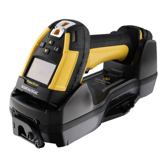
- Page 1 PowerScan™ Family PD/PM/PBT9600 PRODUCT REFERENCE GUIDE Industrial Corded and Cordless Handheld Area Imager Bar Code Reader...
- Page 2 Datalogic and the Datalogic logo are registered trademarks of Datalogic S.p.A. in many countries, including the U.S.A. and the E.U. PowerScan is a trademark of Datalogic S.p.A. and/or its affiliates, registered in the U.S. All other trade- marks and brands are property their respective owners.
-
Page 3: Table Of Contents
Charging the Batteries ....................13 Replacing the Batteries ....................14 Linking the Reader ......................14 Link Datalogic Devices to Base ......................14 Link Reader as Serial Device to a Bluetooth Host ................15 Link Reader as HID device to a Bluetooth host ................15 Bluetooth Passkey or Pin Code Entry Request ................16... - Page 4 Interface Selection ......................35 Configuring the Interface ....................36 Customizing Configuration Settings .................39 Using the Programming Bar Codes ....................39 Datalogic Aladdin™ Utility ........................ 39 Interface Settings ..........................39 Configuring Other Features ......................40 Software Version Transmission ....................... 40 Resetting the Product Configuration to Defaults ................40 Restore Custom Default Configuration ..................
- Page 5 TABLE OF CONTENTS OTHER KEYBOARD PARAMETERS ....................73 Encoding Type ...........................73 ALT Output Type ........................80 Keyboard Numeric Keypad .......................81 Keyboard Send Control Characters ..................81 Intercode Delay .........................82 USB Keyboard Speed ........................83 USB-OEM INTERFACE ....................84 USB-OEM Device Usage ......................85 ETHERNET INTERFACE ....................86 DHCP ............................87 Static IP Address ........................87 Subnet Mask ..........................88...
- Page 6 TABLE OF CONTENTS RGB Good Read Color ......................121 Good Read LED Duration ......................122 Good Read: When to Indicate ....................123 Green Spot Duration .......................123 CAMERA CONTROL .........................124 Aiming Pointer ........................124 Pick Mode ..........................124 Illumination Power Level (only for STD, HP, DC models) .............125 Mobile Phone Mode ........................125 Image Capture .........................126 Multiple Labels Ordering by Code Symbology ...............126...
- Page 7 TABLE OF CONTENTS GS1 DataBar Limited to GS1-128 Emulation ................152 CODE 39 ............................153 Code 39 Enable/Disable ......................153 Code 39 Check Character Calculation ..................153 Code 39 Check Character Transmission ................154 Code 39 Start/Stop Character Transmission .................154 Code 39 Full ASCII ........................155 Code 39 Quiet Zones .......................155 Code 39 Length Control ......................156 Code 39 Set Length 1 ......................156...
- Page 8 Compressed 2 of 5 Set Length 2 ....................180 DATALOGIC 2 OF 5 ..........................181 Datalogic 2 of 5 Enable/Disable .....................181 Datalogic 2 of 5 Check Character Calculation ................181 Datalogic 2 of 5 Check Character Transmission ..............182 Datalogic 2 of 5 Length Control .....................182 Datalogic 2 of 5 Set Length 1 ....................183...
- Page 9 TABLE OF CONTENTS Code 93 Set Length 1 ......................205 Code 93 Set Length 2 ......................205 Code 93 Quiet Zones .......................206 MSI ..............................207 MSI Enable/Disable .........................207 MSI Check Character Calculation ...................207 MSI Check Character Transmission ..................208 MSI Length Control .........................208 MSI Set Length 1 ........................209 MSI Set Length 2 ........................209 PLESSEY ............................210 Plessey Enable/Disable ......................210...
- Page 10 TABLE OF CONTENTS MICRO PDF417 ..........................234 Micro PDF417 Enable / Disable ....................234 Micro PDF417 Code 128 GS1-128 Emulation ................234 Micro PDF417 Length Control ....................235 Micro PDF417 Set Length 1 ....................235 Micro PDF417 Set Length 2 ....................236 QR CODE ............................237 QR Code Enable / Disable .......................237 QR Code Length Control ......................237 QR Code Set Length 1 ......................238 QR Code Set Length 2 ......................238...
- Page 11 TABLE OF CONTENTS Append Code ...........................268 Echo ............................269 Keypress Sound ........................269 Lower Case ..........................270 Enable Legend .........................270 Set Function Key Labels ......................271 BARCODE/KEY DIFFERENT DATA FORMAT ..................272 Set Barcode Header ........................272 Set Barcode Terminator ......................272 Set Key Sequence ID .......................273 Set Key Sequence Header ......................273 Set Key Sequence Terminator ....................273 Set String ID ..........................274...
- Page 12 TABLE OF CONTENTS Bluetooth HID Alt Mode ......................306 FEATURES FOR STAR MODELS ONLY ...................307 STAR Radio Protocol Timeout ....................307 STAR Radio Transmit Mode ....................307 4 Digit Address Stamping .......................309 Assign Unique Address to the Gun ..................309 4 Digit Cradle Address Stamping ...................310 Cradle Address Stamping .......................310 Cradle Address Delimiter .......................311 STAR System Speed .......................311...
- Page 13 TABLE OF CONTENTS Cursor Control ......................344 Font Selection ......................344 Clearing Display ......................345 LED and Beeper Control ....................345 Setting RTC ......................... 345 APPENDIX A. TECHNICAL SPECIFICATIONS ............346 PD9600 Technical Specifications ................... 346 PM/PBT9600 Technical Specifications ................348 Decoding Capabilities ....................
-
Page 14: Preface
Programming can alternatively be performed using the Datalogic Aladdin™ Configura- tion application, which is available from the Datalogic website listed on the back cover of this manual. This multi-platform utility program allows device configuration using a PC. -
Page 15: Manual Conventions
OVERVIEW , Scancode Tables lists control character emulation information for USB Key- Appendix H board interfaces. , ASCII Chart lists hexadecimal reference values for ASCII characters. Appendix I Manual Conventions The following conventions are used in this document: The symbols listed below are used in this manual to notify the reader of key issues or procedures that must be observed when using the reader: NOTE: This symbol draws attention to details or procedures that may be useful in improving, maintaining, or enhancing the performance of the... -
Page 16: Ergonomic Recommendations
TECHNICAL SUPPORT Support Through the Website Datalogic provides several services as well as technical support through its website. Log on to (www.datalogic.com). For quick access, from the home page click on the search icon , and type in the name of the product you’re looking for. -
Page 17: Chapter 1. Introduction
2D codes; the Document Capture model, available for the PD9630 and the PBT9600, is thought for Wide Angle code reading and Document Capture applications. The PowerScan 9600 area imagers also feature Datalogic’s exclusive 3 Green Lights (3GL™) for superior good-read feedback together with a loud beeper and vibration. The ‘Green Spot’... -
Page 18: General Features
To read a symbol or capture an image, simply aim the reader and pull the trigger. The PowerScan™ PD/PM/PBT9600 is a powerful omni-directional reader, so the orientation of the symbol is not important. Datalogic's exclusive patented 'Green Spot' for good- read feedback helps to improve productivity in noisy environments or in situations where silence is required. -
Page 19: Pm9600 4-Key And 16-Key Models
USA Driver License PDF417 barcodes. This fea- USA Driver License Pars- ture can be enabled using either Datalogic Aladdin™ or the bar- codes in the USA Driver License Parsing Quick Reference Guide (QRG), available on the Datalogic website. - Page 20 INTRODUCTION The 4-key keyboard has two fully configurable generic Function keys (F1 and F2) and two arrow keys. These keys are fully customizable to perform specific tasks (e.g. scrolling the list of items, navigating menus, etc.). The 16 keys keyboard is active in numeric data-entry mode by default.
-
Page 21: Battery Safety (Only For Pm/Pbt9600)
Use only the authorized power supplies, battery pack, chargers, and docks supplied by your Datalogic reseller. The use of any other power supplies can damage the device and void your warranty. Do not disassemble or modify the battery. The battery contains safety and pro- tection devices, which, if damaged, may cause the battery to generate heat, explode or ignite. -
Page 22: Programming The Reader
In addition, Aladdin makes it easy to upgrade the handheld’s firmware, to attain the bene- fits of new reader features. Reference the Datalogic Aladdin™ Online Help for more details. Aladdin is available for download free of charge on the Datalogic website. -
Page 23: Chapter 2. Setup
CHAPTER 2 SETUP UNPACKING Check carefully to ensure the reader and any cables or accessories ordered are present and undamaged. If any damage occurred during shipment, contact " Technical Support" on page xvi SETTING UP THE POWERSCAN™ PD9600 READER Follow the steps below to connect and get your reader up and communicating with its host. -
Page 24: Rs-232 Serial Connection
SETUP 2. Insert the circular RJ45 cable (figure A) or use the adapter with non-circular RJ45 cables (figure B). 3. In this case, make sure to insert the adapter with the slot facing up (C). The rib (D) inside the adapter seat must fit into this slot. 4. -
Page 25: Usb Connection
CONNECTING THE HOST INTERFACE USB Connection Connect the reader to a USB port on the terminal/PC using the correct USB cable for the interface type you ordered. USB: Select to communicate either by USB OEM, USB COM STD or USB Keyboard inter- face types by scanning the appropriate interface type bar codes available in this manual. -
Page 26: Cm9681 Power Over Ethernet (Poe) Connection
SETUP CM9681 ETHERNET POE connection CM9681 ETHERNET External Power Supply Brown:+10/30 VDC Blue: GND Black: Not used CAUTION: To avoid damage to the scanner and/or to the host, first install correctly the cable into the scanner and then connect the other end of the cable into the host port of the PC. -
Page 27: Cm9681 External Power Connection
USING THE POWERSCAN™ PD9600 CM9681 External Power Connection DESCRIPTION BROWN 10-30V NOT USED (WITH HOLE) BLUE GND BLACK NOT USED (WITH HOLE) CM9680-81 Compatible Cables CABLE PART NUMBER PWR-IN CONNECTOR M12 5P F. A-Coded 93A050045 CABLE RS232 2M POT COIL IP67* CAB-559 3-POLE STRAIGHT CABLE 3M 95A251290... -
Page 28: Setting Up The Powerscan™ Pm/Pbt9600 Reader
PBT/PM9600 and spare battery pack parts must be periodically recharged. For instance, by using a BC9600 base station powered up with a 12V Datalogic AC/DC adapter (cod.8-0935) for at least 30 minutes each 3 months. -
Page 29: Charging The Batteries
NOTE: The PowerScan PM/PBT9600 may get warm during charging: this is normal and does not mean a malfunction. NOTE: Before using the battery, read "Battery Safety" page 5 . Datalogic recommends annual replacement of rechargeable battery packs to ensure maximum performance. -
Page 30: Replacing The Batteries
3. Invert the sequence to insert the battery and lock the battery door. LINKING THE READER Link Datalogic Devices to Base Before configuring the interface it is necessary to link the handheld with the base. To link the handheld and the base simply put it into the base. If the reader was previ- ously linked to another base, you must first scan the Unlink bar code before re-linking to the new base. -
Page 31: Link Reader As Serial Device To A Bluetooth Host
LINKING THE READER Link Reader as Serial Device to a Bluetooth Host Use this procedure to let the PowerScan PBT9600 communicate with a Bluetooth host using the Bluetooth Serial Port Profile (SPP). 1. If using a Bluetooth adapter on the host device, install any driver provided with the adapter. -
Page 32: Bluetooth Passkey Or Pin Code Entry Request
SETUP Bluetooth Passkey or Pin Code Entry Request During the pairing process, based on Host and Reader security settings, you may need to enter a Bluetooth passkey or PIN code. When requested by the Host, simply enter the displayed code by scanning the corresponding bar codes for alphanumeric entry listed . -
Page 33: Using The Bc9600 Base Station
USING THE BC9600 BASE STATION USING THE BC9600 BASE STATION The BC9600 base station, when paired with one or more PowerScan™ PM/PBT9600 readers, builds a Cordless Reading System for the collection, decoding and transmission of bar code data. It can be connected to a Host PC via RS232, USB, USB Type C, or Ether- net, depending on the interchangeable connection module. -
Page 34: Base Station Models
SETUP BASE STATION MODELS Each base station is composed of a cradle which must be connected to a connection module, depending on the interface desired and on the IP (water and dust) protection grade. The base station and connection module models are listed below. Base Station Models BC9600-433 BASE/CHARGER 433MHZ w/o conn. -
Page 35: Wall Mounting
MOUNTING INSTRUCTIONS NOTE: For vertical installation, do not exceed two meters in height. NOTE: When mounting on drywall, the base station should be screwed to a wall stud or supporting beam for additional support. Screw Position Screw Position Wall Mounting The base station contains a reversible positioning tab for horizontal or vertical mounting. - Page 36 SETUP 2. Carefully lift the tab out. 3. Rotate the tab until you will see "WALL" tooth, put the rotated tab into place and secure it with the screw. POWERSCAN™ PD/PM/PBT9600...
-
Page 37: Portable Desktop Mounting
MOUNTING INSTRUCTIONS Portable Desktop Mounting For desktop mounting, if portability of the base station is required, the mounting plate can be used. There are two ways this can be done: (1) base station fast release by first fixing the mounting plate onto a flat surface so the base station can be slid off and on, or (2) connection module fast release by fixing the mounting plate to the connection module and then fixing both of them onto a flat surface so only the cradle can be slid off while the connection module will remain on the desk. - Page 38 SETUP 3. Align the base station with the mounting plate until you see the sphere inside the bigger hole on the left. 4. Move the base station down until the sphere is aligned with the smaller hole. POWERSCAN™ PD/PM/PBT9600...
-
Page 39: Connection Module Fast Release - Mounting The Bracket
CONNECTION MODULE FAST RELEASE - MOUNTING THE BRACKET CONNECTION MODULE FAST RELEASE - MOUNTING THE BRACKET 1. Remove the protective strips. 2. Unscrew the connection module from the base station. 3. Screw the mounting plate to the connection module. 4. Unlock the lever and remove the connection module from the base station. 5. - Page 40 SETUP 6. With the lever still unlocked, align the base station with the connection module until you see the sphere inside the bigger hole on the right. 7. Move the base station up until the sphere is aligned with the smaller hole, then lock the lever to secure the connection module.
-
Page 41: System Connections
SYSTEM CONNECTIONS SYSTEM CONNECTIONS CAUTION: Connections should always be made with power off. The BC9630 (BC9600 + CM9630 connection module) provides a multi-interface connec- tor for connections to a host and a power supply connector for an external power sup- ply. -
Page 42: Connecting And Disconnecting The Cables
SETUP CONNECTING AND DISCONNECTING THE CABLES The BC963X cradle can be connected to a host by means of a multi-interface cable, which must be simply plugged into the Host connector, visible on the front panel of the cradle. To disconnect the multi-interface cable and the power adapter cable (for BC9630), refer to the following figures. -
Page 43: Disconnecting Bc9630 Cables
CONNECTING AND DISCONNECTING THE CABLES Disconnecting BC9630 Cables To disconnect the cables, power off the base station, unlock the lever and press down the cable clip using a pen or a similar tool. 1. Power off the cradle and unlock the lever Unlock the lever 2. -
Page 44: Connecting Bc9631 Multi-Interface Cable
SETUP Connecting BC9631 Multi-interface Cable 1. Unscrew the no-tool screw to open the front door. Unscrew 2. Insert the multi-interface cable. Insert 3. Close the door and screw it back. Screw To disconnect the multi-interface cable, open the front door, pull out the cable and screw the front door back. -
Page 45: Connecting Bc9680 Cables
CONNECTING AND DISCONNECTING THE CABLES Connecting BC9680 cables Connect the Ethernet cable and then connect the power adapter cable. Finally, power on the cradle and lock the power cable on the strain relief. To disconnect the cables, first unlock the power cable and then pull it out. To disconnect the Ethernet cable, use a flat screwdriver to unlock the Ethernet clip. - Page 46 SETUP CAUTION: Do not place two base stations too close to each other as shown in the figure below. Keep at least 5cm of distance between them, in order to avoid possible interferences and malfunction of the two wireless charging systems. POWERSCAN™...
-
Page 47: Connecting The Base Station
CONNECTING THE BASE STATION CONNECTING THE BASE STATION The BC9600 can be connected to a terminal, PC or other host device by means of a multi-interface cable or via Ethernet. The following figures show how to connect the cradle to the host device. Turn off the host before connection and consult the manual for that equipment (if necessary) before proceeding. - Page 48 SETUP The power supply is optional, the cradle can be powered by the USB port. In this case, the full charging of an empty battery will take about 16 hours with USB and 6,5 hours with USB type C at ambient temperature. For intense usage and/or when the system is shut down during the night, the use of an external power supply is recommended.
- Page 49 CONNECTING THE BASE STATION ETHERNET BC9681 with POE connection ETHERNET BC9681 with external power supply Brown: +10/30 VDC Blue: GND Black: Not used For the pinout and the list of compatible cables refer to the information about CM9680/ CM9681 at page 10 PRODUCT REFERENCE GUIDE...
-
Page 50: System And Network Layouts
SETUP SYSTEM AND NETWORK LAYOUTS Stand Alone Layouts Figure 6 - Single Reader Layout Figure 7 - Multiple Reader Layout In stand alone systems, each base station is connected to a single Host. Figure 8 - Multiple Stand Alone Layouts Many stand alone connections can operate in the same physical area without interfer- ence, provided all readers and base stations in the system have different addresses. -
Page 51: Bc9600 Configuration
BC9600 CONFIGURATION BC9600 CONFIGURATION The BC9600 configuration can be performed in three ways: by using the Datalogic Alad- din™ software configuration program, by sending configuration strings from the Host PC via the RS-232, USB-COM or Ethernet interface or by reading configuration bar codes with the PowerScan 9600 reader. -
Page 52: Configuring The Interface
SETUP CONFIGURING THE INTERFACE Scan the programming bar code from the following section which selects the appropri- ate interface type to match the system the reader will be connected to. Next, proceed to the corresponding chapter in this manual (also listed in the table) to configure any desired settings and features associated with that interface. - Page 53 RS-232 for use with OPOS/UPOS/JavaPOS $P,HA13,P Select RS-232 OPOS USB-COM (simulates RS-232 standard interface) $P,HA47,P Select USB-COM-STD a. Download the correct USB Com driver from www.datalogic.com. USB FOR TERMINALS USB Toshiba TEC $P,HA41,P Select USB Toshiba TEC USB HID POS $P,HA44,P...
- Page 54 SETUP KEYBOARD USB Keyboard with standard key encoding $P,HA35,P Select USB Keyboard USB Keyboard with alternative key encoding $P,HA2B,P Select USB Alternative Keyboard USB-Composite Combines USB-KBD emulation and USB-COM $P,HA4D,P Select USB-Composite POWERSCAN™ PD/PM/PBT9600...
-
Page 55: Customizing Configuration Settings
Datalogic Aladdin™ is a multi-platform utility program providing a quick and user- friendly configuration method via the RS-232/USB-COM/Ethernet interface. The Aladdin utility is available on the Datalogic website. Aladdin allows you to program the reader by selecting configuration commands through a user-friendly graphical interface running on a PC. -
Page 56: Configuring Other Features
SETUP Configuring Other Features If your installation requires different programming than the standard factory default settings, the following sections of this manual allow configuration of non-interface-spe- cific settings you might require: Configuration Using Bar Codes: General Features includes programming for scanning, beeper and LED indicators and other such universal settings. -
Page 57: Chapter 3. Configuration With Bar Codes
CHAPTER 3 CONFIGURATION WITH BAR CODES This and following sections provide programming bar codes to configure your reader by changing the default settings. For details about additional methods of programming, see " Customizing Configuration Settings" on page 39 NOTE: You must first enable your PowerScan to read bar codes in order to use this section. -
Page 58: Symbology-Specific Parameters
CONFIGURATION WITH BAR CODES Symbology-specific parameters: define 1D Symbologies, starting on page 130 2D Symbologies, starting on page 215 options for all symbologies and provides the programming bar codes necessary for con- figuring these features. NOTE: You must first enable your reader to read bar codes in order to use this section. -
Page 59: Global Interface Features
GLOBAL INTERFACE FEATURES ENTER/EXIT PROGRAMMING MODE GLOBAL INTERFACE FEATURES The following interface features are configurable by all interface types. To set features specific to your interface, turn to that section of this manual. Host Commands — Obey/Ignore This option specifies whether the reader will obey or ignore host commands. See list of available host command characters in . -
Page 60: Rs-232 Interface
CONFIGURATION | RS-232 INTERFACE Use the programming bar codes in this chapter if modifications to the standard RS-232 interface settings are necessary to meet your system’s requirements. Additional settings which apply to both the RS-232 and USB interfaces are available in RS-232/USB-COM Settings, starting on page 50 SECTION CONTENTS... -
Page 61: Rs-232 Standard Settings
RS-232 STANDARD SETTINGS ENTER/EXIT PROGRAMMING MODE RS-232 STANDARD SETTINGS Baud Rate Baud rate is the number of bits of data transmitted per second. Set the reader's baud rate to match the baud rate setting of the host device. With an improper baud rate set- ting, data may not reach the host correctly. -
Page 62: Data Bits
ENTER/EXIT PROGRAMMING MODE RS-232 INTERFACE Data Bits This parameter allows the reader to interface with devices requiring a 7-bit or 8-bit ASCII protocol for sending and receiving data. $CR2DA00 7 Data Bits $CR2DA01 8 Data Bits NOTE: Handheld and base station models support the 8-bit ASCII protocol. The 7-bit ASCII protocol support is subject to specific firmware release. -
Page 63: Parity
RS-232 STANDARD SETTINGS ENTER/EXIT PROGRAMMING MODE Parity This feature specifies parity required for sending and receiving data. A parity check bit is the most significant bit of each ASCII coded character. Select the parity type according to host device requirements. •... -
Page 64: Handshaking Control
ENTER/EXIT PROGRAMMING MODE RS-232 INTERFACE Handshaking Control The data interface consists of an RS-232 port designed to operate either with or without the hardware handshaking lines, Request to Send (RTS), and Clear to Send (CTS). Hand- shaking Control includes the following options: •... -
Page 65: Rs-232/Usb-Com Interfaces
CONFIGURATION | RS-232/USB-COM INTERFACES SECTION CONTENTS • Intercharacter Delay • ACK NAK Timeout Value • Beep On ASCII BEL • ACK NAK Retry Count • Beep On Not on File • ACK NAK Error Handling • ACK NAK Options • Indicate Transmission Failure •... -
Page 66: Rs-232/Usb-Com Settings
ENTER/EXIT PROGRAMMING MODE RS-232/USB-COM INTERFACES RS-232/USB-COM SETTINGS Intercharacter Delay This parameter specifies the intercharacter delay between the end of one character and the beginning of the next. The delay can be set within a range of zero (0) to 990 millisec- onds in 10ms increments. -
Page 67: Beep On Ascii Bel
RS-232/USB-COM SETTINGS ENTER/EXIT PROGRAMMING MODE Beep On ASCII BEL When this parameter is enabled, the reader issues a beep when a <BEL> character is detected on the RS-232 serial line. <BEL> is issued to gain a user's attention to an illegal entry or other important event. -
Page 68: Ack Nak Options
ENTER/EXIT PROGRAMMING MODE RS-232/USB-COM INTERFACES ACK NAK Options This enables/disables the ability of the reader to support the RS-232 ACK/NAK protocol. When configured, the reader and/or host sends an “ACK” when it receives data prop- erly, and sends “NAK” when the data is in error. Options are: •... -
Page 69: Ack Character
RS-232/USB-COM SETTINGS ENTER/EXIT PROGRAMMING MODE ACK Character This setting specifies an ASCII character or hex value to be used as the ACK character. ASCII characters or any hex value from 0 to 0xFF can be selected. See " ACK Character" on for more detailed programming instructions. -
Page 70: Ack Nak Timeout Value
ENTER/EXIT PROGRAMMING MODE RS-232/USB-COM INTERFACES ACK NAK Timeout Value This option specifies the amount of time the reader waits for an ACK character from the host following label transmission. The selectable timeout range is 200 milliseconds to 15,000ms (15 seconds) in 200ms increments. A selection of 0 disables the timeout. See "... -
Page 71: Ack Nak Error Handling
RS-232/USB-COM SETTINGS ENTER/EXIT PROGRAMMING MODE ACK NAK Error Handling This feature specifies the method the reader uses to handle receive errors detected while waiting for an ACK character from the host. Options are: • Ignore errors detected • Process error as valid ACK character •... -
Page 72: Disable Character
ENTER/EXIT PROGRAMMING MODE RS-232/USB-COM INTERFACES Disable Character Specifies the value of the RS-232 host command used to disable the reader. ASCII characters or any hex value from 0 to 0xFF can be selected. See " Disable Character" for more detailed programming instructions. on page 321 Setting to previously defined characters such as XON, XOFF, or host com- mands conflicts with normal operation of these characters. -
Page 73: Keyboard Interface
CONFIGURATION | KEYBOARD INTERFACE SECTION CONTENTS OUNTRY starting on page 58 • Setting Country Mode THER EYBOARD ARAMETERS starting on page 73 • Encoding Type • Keyboard Send Control Characters • ALT Output Type • Intercode Delay • Keyboard Numeric Keypad •... -
Page 74: Country Mode
COUNTRY MODE This feature specifies the country/language supported by the keyboard. The Country Mode setting is ignored if the interface uses alternate key encoding. SETUP ON PC TO USE ALT UNIVERSAL 1. Open Registry Edit 2. Set EnableHexNumpad to 1 as follows: 3. -
Page 75: Setting Country Mode
COUNTRY MODE ENTER/EXIT PROGRAMMING MODE Setting Country Mode $CKBCO00 United States $CKBCO01 French International (Belgian French) $CKBCO02 United Kingdom $CKBCO03 Danish $CKBCO04 French (France) $CKBCO05 German $CKBCO06 Italian PRODUCT REFERENCE GUIDE... - Page 76 ENTER/EXIT PROGRAMMING MODE KEYBOARD INTERFACE Setting Country Mode (continued) $CKBCO07 Norwegian $CKBCO08 Portuguese (Portugal) $CKBCO09 Spanish $CKBCO0A Swedish $CKBCO0B Swiss French $CKBCO0C Japanese ASCII $CKBCO0D Hungarian POWERSCAN™ PD/PM/PBT9600...
- Page 77 COUNTRY MODE ENTER/EXIT PROGRAMMING MODE Setting Country Mode (continued) $CKBCO0E Czech $CKBCO0F Slovak $CKBCO10 Romanian $CKBCO11 Croatian $CKBCO12 Polish_214 $CKBCO13 French Canadian Win7 $CKBCO14 Lithuanian PRODUCT REFERENCE GUIDE...
- Page 78 ENTER/EXIT PROGRAMMING MODE KEYBOARD INTERFACE Setting Country Mode (continued) $CKBCO17 Vietnamese $CKBCO18 Russian $CKBCO19 Arabic 101 $CKBCO1A Chinese ASCII $CKBCO1B Thai-Kedmanee $CKBCO1C Albanian $CKBCO1D Arabic 102 POWERSCAN™ PD/PM/PBT9600...
- Page 79 COUNTRY MODE ENTER/EXIT PROGRAMMING MODE Setting Country Mode (continued) $CKBCO1E Arabic 102 AZERTY $CKBCO1F Azeri Cyrillic $CKBCO20 Azeri Latin $CKBCO21 Belarusian $CKBCO22 Bosnian Cyrillic $CKBCO23 Bosnian Latin $CKBCO24 Bulgarian Cyrillic PRODUCT REFERENCE GUIDE...
- Page 80 ENTER/EXIT PROGRAMMING MODE KEYBOARD INTERFACE Setting Country Mode (continued) $CKBCO25 Bulgarian Latin $CKBCO26 Canadian French (Legacy) $CKBCO27 Canadian Multilingual $CKBCO28 Chinese (Simplified) $CKBCO29 Chinese (Traditional) $CKBCO2A Czech Programmers $CKBCO2B Czech QWERTY POWERSCAN™ PD/PM/PBT9600...
- Page 81 COUNTRY MODE ENTER/EXIT PROGRAMMING MODE Setting Country Mode (continued) $CKBCO2C Dutch Netherlands $CKBCO2D Estonian $CKBCO2E Faeroese $CKBCO2F Finnish $CKBCO30 French (Canada) 2000/XP $CKBCO31 French (Canada) 95/98 $CKBCO32 Galician PRODUCT REFERENCE GUIDE...
- Page 82 ENTER/EXIT PROGRAMMING MODE KEYBOARD INTERFACE Setting Country Mode (continued) $CKBCO33 Greek $CKBCO34 Greek Latin $CKBCO35 Greek Polytonic $CKBCO36 Greek220 $CKBCO37 Greek220 Latin $CKBCO38 Greek319 $CKBCO39 Greek319 Latin POWERSCAN™ PD/PM/PBT9600...
- Page 83 COUNTRY MODE ENTER/EXIT PROGRAMMING MODE Setting Country Mode (continued) $CKBCO3A Hebrew Israel $CKBCO3B Hungarian_101KEY $CKBCO3C Icelandic $CKBCO3D Irish $CKBCO3E Italian_142 $CKBCO3F Japanese (Shift-JIS) $CKBCO40 Kazakh PRODUCT REFERENCE GUIDE...
- Page 84 ENTER/EXIT PROGRAMMING MODE KEYBOARD INTERFACE Setting Country Mode (continued) $CKBCO41 Korean (Hangul) $CKBCO42 Korean ASCII $CKBCO43 Kyrgyz Cyrillic $CKBCO44 Latin America $CKBCO45 Latvian $CKBCO46 Latvian QWERTY POWERSCAN™ PD/PM/PBT9600...
- Page 85 COUNTRY MODE ENTER/EXIT PROGRAMMING MODE Setting Country Mode (continued) $CKBCO48 Macedonian -FYROM $CKBCO49 Maltese_47KEY $CKBCO4A Mongolian-Cyrillic $CKBCO4B Polish Programmer $CKBCO4C Portuguese Brazil $CKBCO4D Portuguese Brazilian ABNT $CKBCO4E Portuguese Brazilian ABNT2 PRODUCT REFERENCE GUIDE...
- Page 86 ENTER/EXIT PROGRAMMING MODE KEYBOARD INTERFACE Setting Country Mode (continued) $CKBCO4F Romanian Legacy $CKBCO50 Romanian Programmer $CKBCO51 Romanian Standard $CKBCO52 Russian Typewriter $CKBCO53 Serbian Cyrillic $CKBCO54 Serbian Latin $CKBCO55 Slovak QWERTY POWERSCAN™ PD/PM/PBT9600...
- Page 87 COUNTRY MODE ENTER/EXIT PROGRAMMING MODE Setting Country Mode (continued) $CKBCO56 Slovenian $CKBCO57 Spanish Variation $CKBCO58 Swiss German $CKBCO59 Tatar $CKBCO5A Turkish F $CKBCO5B Turkish Q $CKBCO5C Ukrainian PRODUCT REFERENCE GUIDE...
- Page 88 ENTER/EXIT PROGRAMMING MODE KEYBOARD INTERFACE Setting Country Mode (continued) $CKBCO5D US Dvorak $CKBCO5E US Dvorak Left Hand $CKBCO5F US Dvorak Right Hand $CKBCO60 US English (Mac) $CKBCO61 US English (North American) $CKBCO62 US International $CKBCO63 Uzbek Cyrillic POWERSCAN™ PD/PM/PBT9600...
-
Page 89: Other Keyboard Parameters
OTHER KEYBOARD PARAMETERS ENTER/EXIT PROGRAMMING MODE OTHER KEYBOARD PARAMETERS Encoding Type $CENCO00 Encoding Type = Don’t Use Encoding $CENCO03 Encoding Type = UTF_8 $CENCO04 Encoding Type = Windows 874 $CENCO05 Encoding Type = Windows 932 $CENCO06 Encoding Type = Windows 936 $CENCO07 Encoding Type = Windows 949 $CENCO08... - Page 90 ENTER/EXIT PROGRAMMING MODE KEYBOARD INTERFACE Encoding Type (continued) $CENCO09 Encoding Type = Windows 1250 $CENCO0A Encoding Type = Windows 1251 $CENCO0B Encoding Type = Windows 1252 $CENCO0C Encoding Type = Windows 1253 $CENCO0D Encoding Type = Windows 1254 $CENCO0E Encoding Type = Windows 1255 $CENCO0F Encoding Type = Windows 1256 POWERSCAN™...
- Page 91 OTHER KEYBOARD PARAMETERS ENTER/EXIT PROGRAMMING MODE Encoding Type (continued) $CENCO10 Encoding Type = Windows 1257 $CENCO11 Encoding Type = Windows 1258 $CENCO12 Encoding Type = Windows 20866 $CENCO31 Encoding Type = Windows 54936 $CENCO13 Encoding Type = ISO 8859-1 $CENCO14 Encoding Type = ISO 8859-2 $CENCO15 Encoding Type = ISO 8859-3...
- Page 92 ENTER/EXIT PROGRAMMING MODE KEYBOARD INTERFACE Encoding Type (continued) $CENCO16 Encoding Type = ISO 8859-4 $CENCO17 Encoding Type = ISO 8859-5 $CENCO18 Encoding Type = ISO 8859-6 $CENCO19 Encoding Type = ISO 8859-7 $CENCO1A Encoding Type = ISO 8859-8 $CENCO1B Encoding Type = ISO 8859-9 $CENCO1C Encoding Type = ISO 8859-10 POWERSCAN™...
- Page 93 OTHER KEYBOARD PARAMETERS ENTER/EXIT PROGRAMMING MODE Encoding Type (continued) $CENCO1D Encoding Type = ISO 8859-11 $CENCO1E Encoding Type = ISO 8859-13 $CENCO1F Encoding Type = ISO 8859-14 $CENCO20 Encoding Type = ISO 8859-15 $CENCO21 Encoding Type = ISO 8859-16 $CENCO22 Encoding Type = MS-DOS 437 $CENCO23 Encoding Type = MS-DOS 737...
- Page 94 ENTER/EXIT PROGRAMMING MODE KEYBOARD INTERFACE Encoding Type (continued) $CENCO24 Encoding Type = MS-DOS 775 $CENCO25 Encoding Type = MS-DOS 850 $CENCO26 Encoding Type = MS-DOS 852 $CENCO27 Encoding Type = MS-DOS 855 $CENCO28 Encoding Type = MS-DOS 857 $CENCO29 Encoding Type = MS-DOS 860 $CENCO2A Encoding Type = MS-DOS 861 POWERSCAN™...
- Page 95 OTHER KEYBOARD PARAMETERS ENTER/EXIT PROGRAMMING MODE Encoding Type (continued) $CENCO2B Encoding Type = MS-DOS 862 $CENCO2C Encoding Type = MS-DOS 863 $CENCO2D Encoding Type = MS-DOS 865 $CENCO2E Encoding Type = MS-DOS 866 $CENCO2F Encoding Type = MS-DOS 869 $CENCO30 Encoding Type = Mac CP10000 PRODUCT REFERENCE GUIDE...
-
Page 96: Alt Output Type
ENTER/EXIT PROGRAMMING MODE KEYBOARD INTERFACE ALT Output Type This option specifies the encode type of ALT Mode when the reader sends Output Key- board Data in Alt Mode. (Be aware that the reader may switch automatically between ALT mode & Normal Keyboard Scancode, to correctly display some characters that are not present in the current Keyboard Country). -
Page 97: Keyboard Numeric Keypad
OTHER KEYBOARD PARAMETERS ENTER/EXIT PROGRAMMING MODE Keyboard Numeric Keypad This feature specifies if numeric characters will be sent using the standard keys or the numeric keypad. $CKBKP00 Keyboard Numeric Keypad = Standard Keys $CKBKP01 Keyboard Numeric Keypad = Numeric Keypad Keyboard Send Control Characters This feature is used by USB Keyboard interfaces. -
Page 98: Intercode Delay
ENTER/EXIT PROGRAMMING MODE KEYBOARD INTERFACE Intercode Delay Specifies the delay between labels transmitted to the host for this interface. The select- able range for this feature is from 0 to 99 seconds. See " Intercode Delay" on page 323 more detailed programming instructions To configure this feature, scan the ENTER/EXIT PRO- GRAMMING MODE bar code above, then the bar code at left followed by the digits from the Alphanu-... -
Page 99: Usb Keyboard Speed
OTHER KEYBOARD PARAMETERS ENTER/EXIT PROGRAMMING MODE USB Keyboard Speed This option specifies the USB poll rate for a USB Keyboard. NOTE: This feature applies ONLY to the USB Keyboard interface. $CKBSP01 USB Keyboard Speed = 1ms $CKBSP02 USB Keyboard Speed = 2ms $CKBSP03 USB Keyboard Speed = 3ms $CKBSP05... -
Page 100: Usb-Oem Interface
CONFIGURATION | USB-OEM INTERFACE SECTION CONTENTS • USB-OEM Device Usage POWERSCAN™ PD/PM/PBT9600... -
Page 101: Usb-Oem Device Usage
ENTER/EXIT PROGRAMMING MODE USB-OEM Device Usage The USB-OEM protocol allows for the reader to be identified as one of two different types of bar code reader. Depending on what other reader you may already have con- nected to a USB-OEM POS, you may need to change this setting to enable all devices to communicate. -
Page 102: Ethernet Interface
CONFIGURATION | ETHERNET INTERFACE The following feature is specific to CM968x. In order to configure the following configu- ration item, the scanner must be previously set up and configured in Ethernet interface. Then CM968x must be connected. SECTION CONTENTS • DHCP •... -
Page 103: Dhcp
ENTER/EXIT PROGRAMMING MODE DHCP When DHCP is Enabled, the CM968x dynamically obtains an Internet Protocol (IP) address from a Dynamic Host Configuration Protocol (DHCP) server. Otherwise, static IP address are used. $CETDC00 DHCP = Disable $CETDC01 DHCP = Enable Static IP Address This feature sets a Static IP address for the CM968x. -
Page 104: Subnet Mask
ENTER/EXIT PROGRAMMING MODE ETHERNET INTERFACE Subnet Mask The subnet mask number is combined with the IP address number to identify which net- work segment the CM968x is on. A subnet mask is a 32-bit number that is composed by using four numbers from 0 through 255, separated by periods. -
Page 105: Dns1 Address
ENTER/EXIT PROGRAMMING MODE DNS1 Address This is the address of the preferred or primary DNS server for the CM968x. This server is used first, to resolve DNS names to IP addresses for DNS names queried by this com- puter that cannot be resolved by using local name resolution information (such as cached DNS names or names contained in a Hosts file). -
Page 106: Device Name
ENTER/EXIT PROGRAMMING MODE ETHERNET INTERFACE Device Name This parameter is used to uniquely identify one CM968x from other Datalogic devices. To configure, scan the ENTER/EXIT PROGRAMMING MODE bar code above, then the bar code at left fol- lowed by the digits (in hex) from the Alphanumeric... -
Page 107: Aladdin Socket Port
ENTER/EXIT PROGRAMMING MODE Aladdin Socket Port This parameter will allow the identification of a network service on an IP network (the Internet). It is a mapping to the underlying TCP-IP socket port number used for Aladdin Configuration. To configure, scan the ENTER/EXIT PROGRAMMING MODE bar code above, then the bar code at left fol- lowed by 5 digits from the Alphanumeric characters... -
Page 108: Logger Socket Port
52000 DATA Flow Control Selection The Datalogic Flow Control Mode is a powerful way to manage and optimize the com- munication with the Fieldbus Master. By enabling the FCM a few bytes of the exchange areas are reserved for driver operations and the rest are used by the application layer. -
Page 109: Data Prefix Counter Selection
ENTER/EXIT PROGRAMMING MODE DATA Prefix Counter Selection When Enabled, two character representing a decimal counter are added to transmitted label. The counter goes from 00 to 99, then returns to 00. Ex: when the scanner reads the Label “ABC” multiple times, the result is: 00ABC 01ABC 99ABC... -
Page 110: Scanner Character Terminator
ENTER/EXIT PROGRAMMING MODE ETHERNET INTERFACE Scanner Character Terminator By default CM968x considers a Label transmitted by the scanner 'CR' terminated. If this format is not possible, for instance when “CR” is present in the middle of the labels, it is possible to change the terminator with one or more different characters. To configure, scan the ENTER/EXIT PROGRAMMING MODE bar code above, then the bar code at left fol- lowed by 20 digits (in hex) from the Alphanumeric... -
Page 111: Controller Input Data Buffer Size
ENTER/EXIT PROGRAMMING MODE Controller Input Data Buffer Size Define the size of the controller input data buffer (only for Profinet CM9681-N100). $CEDID00\r Controller Input Data Buffer Size = 8 byte $CEDID01\r Controller Input Data Buffer Size = 16 byte $CEDID02\r Controller Input Data Buffer Size = 32 byte $CEDID03\r Controller Input Data Buffer Size = 64 byte... -
Page 112: Controller Output Data Buffer Size
ENTER/EXIT PROGRAMMING MODE ETHERNET INTERFACE Controller Output Data Buffer Size Define the size of the controller input data buffer (only for Profinet CM9681-N100). $CEDOD00\r Controller Output Data Buffer Size = 8 byte $CEDOD01\r Controller Output Data Buffer Size = 16 byte $CEDOD02\r Controller Output Data Buffer Size = 32 byte $CEDOD03\r... -
Page 113: Data Format
CONFIGURATION | DATA FORMAT SECTION CONTENTS LOBAL ETTINGS starting on page 98 • Global Prefix/Suffix • Global AIM ID • Case Conversion • GS1-128 AIM ID • Character Conversion ABEL starting on page 101 • • Label ID Control Label ID: Pre-loaded Sets •... -
Page 114: Global Settings
ENTER/EXIT PROGRAMMING MODE DATA FORMAT GLOBAL SETTINGS Global Prefix/Suffix Up to 20 ASCII characters may be added as a prefix (in a position before the bar code data) and/or as a suffix (in a position following the bar code data). See in “Ref- page 325 erences”... -
Page 115: Case Conversion
GLOBAL SETTINGS ENTER/EXIT PROGRAMMING MODE Case Conversion This feature allows conversion of the case of all alphabetic characters to upper or lower case. NOTE: Case conversion affects ONLY scanned bar code data, and does not affect Label ID, Prefix, Suffix, or other appended data. $CLFCA00 ... -
Page 116: Global Aim Id
ENTER/EXIT PROGRAMMING MODE DATA FORMAT Global AIM ID NOTE: This feature enables/disables addition of AIM IDs for all symbology types. AIM label identifiers (as opposed to custom characters you select yourself as with label identifiers) can be included with scanned bar code data. See for more detailed page 326 programming instructions. -
Page 117: Label Id
LABEL ID ENTER/EXIT PROGRAMMING MODE LABEL ID A Label ID is a customizable code of up to three ASCII characters (each can be one of hex 0x01-0xFF), used to identify a bar code (symbology) type. It can be appended previous to or following the transmitted bar code data depending upon how this option is enabled. -
Page 118: Label Id: Set Individually Per Symbology
ENTER/EXIT PROGRAMMING MODE DATA FORMAT Label ID: Set Individually Per Symbology This feature configures a Label ID individually for a single symbology. NOTE: This setting requires the scanning of bar codes from multiple sec- tions. See " Label ID: Set Individually Per Symbology" on page 329 for more detailed programming instructions. -
Page 119: Label Id Symbology Selection
LABEL ID ENTER/EXIT PROGRAMMING MODE Label ID Symbology Selection This option selects the symbology for which a Label ID is to be configured. See " Label ID: for full instructions. Set Individually Per Symbology" on page 329 Make a mistake? Scan the CANCEL bar code to abort and not save the entry string. - Page 120 ENTER/EXIT PROGRAMMING MODE DATA FORMAT Label ID Symbology Selection (continued) $C32ID Set EAN-13/P2 Label ID Character(s) $C35ID Set EAN-13/P5 Label ID Character(s) $CISID Set ISBN Label ID Character(s) $CINID Set ISSN Label ID Character(s) $C8BID Set EAN-8 Label ID Character(s) $C82ID Set EAN-8 Label ID Character(s) $C85ID...
- Page 121 LABEL ID ENTER/EXIT PROGRAMMING MODE Label ID Symbology Selection (continued) $CXBID Set GS1 DataBar Expanded Label ID Character(s) $CLBID Set GS1 DataBar Limited Label ID Character(s) $CC3ID Set Code 39 Label ID Character(s) $CP3ID Set Code 32 Label ID Character(s) $CCCID Set Code 39 CIP HR Label ID Character(s) $CC8ID...
- Page 122 Label ID Symbology Selection (continued) $CHRID Set Interleaved 2 of 5 CIP HR Label ID Character(s) $CD2ID Datalogic 2 of 5 Label ID Character(s) $CS2ID Standard 2 of 5 Label ID Character(s) $CU2ID Industrial 2 of 5 Label ID Character(s)
- Page 123 LABEL ID ENTER/EXIT PROGRAMMING MODE Label ID Symbology Selection (continued) $CC1ID Code 11 Label ID Character(s) $CMSID MSI Label ID Character(s) $CPLID Plessey Label ID Character(s) $CALID Anker Plessey Label ID Character(s) $CM2ID Set Matrix 2 of 5 Label ID Character(s) PRODUCT REFERENCE GUIDE...
-
Page 124: Reading Parameters
CONFIGURATION | READING PARAMETERS SECTION CONTENTS CANNING EATURES starting on page 109 • Scan Mode • Stand Mode/Object Detection Sensitivity • Scanning Active Time • Stand Mode/Object Detection Illumination Off Time • Flash On Time • Illumination Intensity • Flash Off Time •... -
Page 125: Scanning Features
SCANNING FEATURES ENTER/EXIT PROGRAMMING MODE SCANNING FEATURES Scan Mode Selects the reader’s scan operating mode. See in “References” for descriptions. page 332 $CSNRM00 Scan Mode = Trigger Single $CSNRM01 Scan Mode = Trigger Hold Multiple $CSNRM02 Scan Mode = Trigger Pulse Multiple $CSNRM03 Scan Mode = Flashing $CSNRM04... -
Page 126: Scanning Active Time
ENTER/EXIT PROGRAMMING MODE READING PARAMETERS Scanning Active Time This setting specifies the amount of time that the reader stays in scan ON state once the state is entered. The range for this setting is from 1 to 255 seconds in 1-second incre- ments. -
Page 127: Flash Off Time
SCANNING FEATURES ENTER/EXIT PROGRAMMING MODE Flash Off Time This feature specifies the OFF time for the indicator LED while in Flash Mode. The select- able range is 100 to 9,900 milliseconds (0.1 to 9.9 seconds), in 100 millisecond incre- ments. See in “References”... - Page 128 ENTER/EXIT PROGRAMMING MODE READING PARAMETERS Double Read Timeout (continued) $CSNDR3C Double Read Timeout = 0.6 Second $CSNDR50 Double Read Timeout = 0.8 Second $CSNDR64 Double Read Timeout = 1 Second POWERSCAN™ PD/PM/PBT9600...
-
Page 129: Stand Detection Behavior (Desk Only)
SCANNING FEATURES ENTER/EXIT PROGRAMMING MODE Stand Detection Behavior (Desk only) Specifies the behavior of the reader when stationary in a stand. Below are further options concerning Stand Operation. Disables mode switching when the reader is placed in a stand. Ignore Autorecognition: Automatically switches the reader to Stand Switch to Stand Mode/Object Detection: Mode/Object Detection when the reader is placed in the stand. -
Page 130: Stand Mode/Object Detection Indication (Stand Mode Flash)
ENTER/EXIT PROGRAMMING MODE READING PARAMETERS Stand Mode/Object Detection Indication (Stand Mode Flash) This operation is useful for indicating when the reader is in Stand Mode. If enabled, the blue indicator will blink when Stand Mode scanning is active. $CSMFL00 Stand Mode/Object Detection Indication = Disable $CSMFL01 Stand Mode/Object Detection Indication = Enable... -
Page 131: Stand Mode/Object Detection Illumination Off Time
04 = Illumination OFF Time 1 second Illumination Intensity With the following settings the illumination intensity can be reduced if needed. Not all hardware versions support this function. Please contact Datalogic Technical Support for more information. $CIPWL64 Illumination Intensity and Frequency = Full Intensity... -
Page 132: Corded Stand Mode
ENTER/EXIT PROGRAMMING MODE READING PARAMETERS Corded Stand Mode This parameter sets the Stand Mode operation for corded models only. $CSMVS00 Corded Stand Mode = Disable $CSMVS01 Corded Stand Mode = Generic Stand Dock Detection Beep If enabled, when the Handheld reader is placed in a dock (base station or corded stand), it will beep. -
Page 133: Led And Beeper Indicators
LED AND BEEPER INDICATORS ENTER/EXIT PROGRAMMING MODE LED AND BEEPER INDICATORS Power On Alert Disables or enables the indication (from the Beeper) that the reader is receiving power. $CBPPU00 Power On Alert = Disable (No Audible Indication) $CBPPU01 Power On Alert = Power-up Beep Good Read Beep Type Specifies whether the good read beep has a mono or bitonal beep sound. -
Page 134: Good Read Beep Frequency
ENTER/EXIT PROGRAMMING MODE READING PARAMETERS Good Read Beep Frequency Adjusts the good read beep to sound at a selectable low, medium or high frequency, selectable from the list below. (Controls the beeper’s pitch/tone.) $CBPFR00 Good Read Beep Frequency = Low $CBPFR01 ... -
Page 135: Good Read Beep Length
LED AND BEEPER INDICATORS ENTER/EXIT PROGRAMMING MODE Good Read Beep Length $CBPLE06 Good Read Beep Length = 60 msec $CBPLE08 Good Read Beep Length = 80 msec $CBPLE0A Good Read Beep Length = 100 msec $CBPLE0C Good Read Beep Length = 120 msec $CBPLE0E Good Read Beep Length = 140 msec $CBPLE10... -
Page 136: Good Read Beeper Volume / Vibration
ENTER/EXIT PROGRAMMING MODE READING PARAMETERS Good Read Beeper Volume / Vibration Selects the beeper volume (loudness) upon a good read beep. There are three select- able volume levels. In addition to three selectable volume levels, the user can also activate a vibration feed- back for good read. -
Page 137: Rgb Good Read Enable
LED AND BEEPER INDICATORS ENTER/EXIT PROGRAMMING MODE RGB Good Read Enable Specifies whether the RGB good read indicator is enabled or disabled. $CRBGE00 RGB Good Read = Disable $CRBGE01 RGB Good Read = Enable RGB Good Read Color Selects the good read LED color. $CRBCL00 RGB Good Read Color = RED $CRBCL01... -
Page 138: Good Read Led Duration
ENTER/EXIT PROGRAMMING MODE READING PARAMETERS Good Read LED Duration This feature specifies the amount of time that the Good Read LED remains on following a good read. The good read LED on time can be set within a range of 100 milliseconds to 25,500 milliseconds (0.1 to 25.5 seconds) in 100ms increments. -
Page 139: Good Read: When To Indicate
LED AND BEEPER INDICATORS ENTER/EXIT PROGRAMMING MODE Good Read: When to Indicate This feature specifies when the reader will provide indication (beep and/or flash its green LED) upon successfully reading a bar code. $CBPIN00 Indicate Good Read = After Decode $CBPIN01 Indicate Good Read = After Transmit $CBPIN02... -
Page 140: Camera Control
ENTER/EXIT PROGRAMMING MODE READING PARAMETERS CAMERA CONTROL Aiming Pointer Enables/disables the aiming pointer for all symbologies. $CTAAP00 Aiming Pointer = Disable $CTAAP01 Aiming Pointer = Enable $CTAAP02 Aiming Pointer = Green Spot Pick Mode Specifies the ability of the reader to decode labels only when they are close to the cen- ter of the aiming pattern. -
Page 141: Illumination Power Level (Only For Std, Hp, Dc Models)
Illumination Power Level = Off Mobile Phone Mode This mode is useful for scanning bar codes displayed on a mobile phone. Other options for this feature can be configured using the Datalogic Aladdin application. $CSNPE00 Mobile Phone Mode = Disable $CSNPE01 ... -
Page 142: Image Capture
ENTER/EXIT PROGRAMMING MODE READING PARAMETERS Image Capture For information and a list of options for Image Capture, use the Datalogic Aladdin con- figuration application, available for free download from the Datalogic Scanning website. Multiple Labels Ordering by Code Symbology This feature allows you to specify the order multiple labels are transmitted by symbol- ogy type. -
Page 143: Motion Features
CONFIGURATION | MOTION FEATURES SECTION CONTENTS OTION EATURES starting on page 127 • Motionless Timeout • Motion Aiming Control • Motion Sensitivity Use this chapter to configure motion settings for the handheld. Reference , for a listing of standard factory settings. Appendix C, Standard Defaults PRODUCT REFERENCE GUIDE... -
Page 144: Motionless Timeout
ENTER/EXIT PROGRAMMING MODE MOTION FEATURES Motionless Timeout The period of time that must expire without detecting any motion, before the reader is assumed to be in a motionless condition. The selectable setting is from 500 to 25,500 milliseconds in 100 millisecond increments. This option relates to such features as Aimer On and Stand Mode/Object Detection scanning with respect to motion. -
Page 145: Motion Aiming Control
MOTION FEATURES ENTER/EXIT PROGRAMMING MODE Motion Aiming Control Enables/Disables the Aiming system when motion is detected. $CMOMD00 Motion Aiming Control = Disable $CMOMD01 Motion Aiming Control = Enable PRODUCT REFERENCE GUIDE... -
Page 146: 1D Symbologies
CONFIGURATION | 1D SYMBOLOGIES SECTION CONTENTS ISABLE YMBOLOGIES GLOBAL FEATURE • starting on • starting on page 131 page 131 5 (I 2 OUPON ONTROL NTERLEAVED • starting on page 133 • starting on page 167 UPC-A 5, F NTERLEAVED EBRABAN •... -
Page 147: Disable All Symbologies
DISABLE ALL SYMBOLOGIES ENTER/EXIT PROGRAMMING MODE DISABLE ALL SYMBOLOGIES Scan this label to disable all symbologies. Disable All Symbologies 1D GLOBAL FEATURE Default settings are indicated at each feature/option with a star. Also reference for a listing of the most widely used set of standard fac- Appendix C, Standard Defaults tory settings. -
Page 148: 1D Normal/Inverse Symbol Control
ENTER/EXIT PROGRAMMING MODE 1D SYMBOLOGIES 1D Normal/Inverse Symbol Control Specifies the options available for decoding normal/negative printed symbols for 1D barcodes. $CIPLR00 Allow only Normal 1D Barcode $CIPLR01 Allow only Inverse 1D Barcode $CIPLR02 Allow both Normal and Inverse 1D Barcode POWERSCAN™... -
Page 149: Coupon Control
COUPON CONTROL ENTER/EXIT PROGRAMMING MODE COUPON CONTROL Coupon Control This feature is used to control the method of processing coupon labels. Options are: • Allow all — allow all coupon bar codes to be decoded • Enable only UPC/EAN — enables only UPC/EAN coupon decoding •... -
Page 150: Upc-A
ENTER/EXIT PROGRAMMING MODE 1D SYMBOLOGIES UPC-A The following options apply to the UPC-A symbology. UPC-A Enable/Disable When disabled, the reader will not read UPC-A bar codes. $CABEN00 UPC-A = Disable $CABEN01 UPC-A = Enable UPC-A Check Character Transmission Enable this option to transmit the check character along with UPC-A bar code data. $CABCT00 UPC-A Check Character Transmission = Don’t Send $CABCT01... -
Page 151: Expand Upc-A To Ean-13
UPC-A ENTER/EXIT PROGRAMMING MODE Expand UPC-A to EAN-13 Expands UPC-A data to the EAN-13 data format. Selecting this feature also changes the symbology ID to match those required for EAN-13. $CAB3B00 UPC-A to EAN-13 = Don’t Expand $CAB3B01 UPC-A to EAN-13 = Expand UPC-A Number System Character Transmission This feature enables/disables transmission of the UPC-A number system character. -
Page 152: Upc-E
ENTER/EXIT PROGRAMMING MODE 1D SYMBOLOGIES UPC-E The following options apply to the UPC-E symbology. UPC-E Enable/Disable When disabled, the reader will not read UPC-E bar codes. $CEBEN00 UPC-E = Disable $CEBEN01 UPC-E = Enable UPC-E Check Character Transmission Enable this option to transmit the check character along with UPC-E bar code data. $CEBCT00 UPC-E Check Character Transmission = Don’t Send $CEBCT01... -
Page 153: Expand Upc-E To Ean-13
UPC-E ENTER/EXIT PROGRAMMING MODE Expand UPC-E to EAN-13 Expands UPC-E data to the EAN-13 data format. Selecting this feature also changes the symbology ID to match those required for EAN-13. $CEB3B00 UPC-E to EAN-13 = Don’t Expand $CEB3B01 UPC-E to EAN-13 = Expand Expand UPC-E to UPC-A Expands UPC-E data to the UPC-A data format. -
Page 154: Upc-E Number System Character Transmission
ENTER/EXIT PROGRAMMING MODE 1D SYMBOLOGIES UPC-E Number System Character Transmission This feature enables/disables transmission of the UPC-E number system character. $CEBNS00 UPC-E Number System Character = Do not transmit $CEBNS01 UPC-E Number System Character = Transmit GTIN Formatting This feature enables/disables the ability to convert UPC-E, UPC-A, EAN-8, and EAN-13 labels into the GTIN 14-character format. -
Page 155: 139
EAN-13 ENTER/EXIT PROGRAMMING MODE EAN-13 The following options apply to the EAN-13 symbology. EAN-13 Enable/Disable When disabled, the reader will not read EAN-13 bar codes. $C3BEN00 EAN-13 = Disable $C3BEN01 EAN-13 = Enable EAN-13 Check Character Transmission Enable this option to transmit the check character along with EAN-13 bar code data. $C3BCT00 EAN-13 Check Character Transmission = Don’t Send $C3BCT01... -
Page 156: Ean-13 Flag 1 Character
ENTER/EXIT PROGRAMMING MODE 1D SYMBOLOGIES EAN-13 Flag 1 Character Enables/disables transmission of an EAN/JAN-13 Flag1 character. The Flag 1 character is the first character of the label $C3BF100 EAN-13 Flag 1 Char = Don’t transmit $C3BF101 EAN-13 Flag 1 Char = Transmit EAN-13 to ISBN Conversion This option enables/disables conversion of EAN-13/JAN-13 Bookland labels starting with 978 to ISBN labels. -
Page 157: Ean-13 To Issn Conversion
EAN-13 ENTER/EXIT PROGRAMMING MODE EAN-13 to ISSN Conversion Enables/disables conversion of EAN/JAN-13 Bookland labels starting with 977 to ISSN labels. $C3BIN00 ISSN = Disable $C3BIN01 ISSN = Enable PRODUCT REFERENCE GUIDE... -
Page 158: 142
ENTER/EXIT PROGRAMMING MODE 1D SYMBOLOGIES EAN-8 The following options apply to the EAN-8 symbology. EAN-8 Enable/Disable When disabled, the reader will not read EAN-8 bar codes. $C8BEN00 EAN-8 = Disable $C8BEN01 EAN-8 = Enable EAN-8 Check Character Transmission Enable this option to transmit the check character along with EAN-8 bar code data. $C8BCT00 EAN-8 Check Character Transmission = Don’t Send $C8BCT01... -
Page 159: Expand Ean-8 To Ean-13
EAN-8 ENTER/EXIT PROGRAMMING MODE Expand EAN-8 to EAN-13 Enable this option to expand EAN-8/JAN-8 labels to EAN-13/JAN-13. $C8B3B00 EAN-8 to EAN-13 = Don’t Expand $C8B3B01 EAN-8 to EAN-13 = Expand PRODUCT REFERENCE GUIDE... -
Page 160: Upc/Ean Global Settings
ENTER/EXIT PROGRAMMING MODE 1D SYMBOLOGIES UPC/EAN GLOBAL SETTINGS This section provides configuration settings for UPC-A, UPC-E, EAN 13 and EAN 8 sym- bologies, and affects all of these unless otherwise marked for each feature description. UPC/EAN Price Weight Check This feature enables/disables calculation and verification of price/weight check digits. Options are •Disabled •Enable 4-digit price-weight check-digit calculation... -
Page 161: Upc/Ean Quiet Zones
UPC/EAN GLOBAL SETTINGS ENTER/EXIT PROGRAMMING MODE UPC/EAN Quiet Zones This feature specifies the number of quiet zones for UPC/EAN labels. Quiet zones are blank areas at the ends of a bar code, typically 10 times the width of the narrowest bar or space in the label. -
Page 162: Optional Add-Ons
ENTER/EXIT PROGRAMMING MODE 1D SYMBOLOGIES Optional Add-ons The reader can be enabled to optionally read the following add-ons (supplementals): • • NOTE: If a UPC/EAN base label and a an add-on are both decoded, the reader will transmit the base label and add-on. If a UPC/EAN base label is decoded without an add-on, the base label will be transmitted without an add-on. -
Page 163: Optional Add-On Timer
UPC/EAN GLOBAL SETTINGS ENTER/EXIT PROGRAMMING MODE Optional Add-On Timer This option sets the time the reader will look for an add-on when an add-on fragment has been seen and optional add-ons are enabled. $CADOT01 Optional Add-on Timer = 10ms $CADOT02 Optional Add-on Timer = 20ms $CADOT03 Optional Add-on Timer = 30ms... -
Page 164: Gs1 Databar™ Omnidirectional
ENTER/EXIT PROGRAMMING MODE 1D SYMBOLOGIES GS1 DATABAR™ OMNIDIRECTIONAL The following options apply to the GS1 DataBar Omnidirectional (formerly RSS-14) sym- bology. GS1 DataBar Omnidirectional Enable/Disable When disabled, the reader will not read GS1 DataBar Omnidirectional bar codes. $C4BEN00 GS1 DataBar Omnidirectional = Disable $C4BEN01 GS1 DataBar Omnidirectional = Enable GS1 DataBar Omnidirectional to GS1-128 Emulation... -
Page 165: Gs1 Databar™ Expanded
GS1 DATABAR™ EXPANDED ENTER/EXIT PROGRAMMING MODE GS1 DATABAR™ EXPANDED The following options apply to the GS1 DataBar Expanded (formerly RSS Expanded) sym- bology. GS1 DataBar Expanded Enable/Disable When disabled, the reader will not read GS1 DataBar Expanded bar codes. $CXBEN00 ... -
Page 166: Gs1 Databar Expanded Length Control
ENTER/EXIT PROGRAMMING MODE 1D SYMBOLOGIES GS1 DataBar Expanded Length Control This feature specifies either variable length decoding or fixed length decoding for the GS1 DataBar Expanded symbology. For variable-length decoding, a minimum length may be set. Variable Length: For fixed-length decoding, two different lengths may be set. Fixed Length: $CXBLC00 ... -
Page 167: Gs1 Databar Expanded Set Length 2
GS1 DATABAR™ EXPANDED ENTER/EXIT PROGRAMMING MODE GS1 DataBar Expanded Set Length 2 This feature specifies one of the bar code lengths for " GS1 DataBar Expanded Length . Length 2 is the maximum label length if in Variable Length Mode, Control"... -
Page 168: Gs1 Databar™ Limited
ENTER/EXIT PROGRAMMING MODE 1D SYMBOLOGIES GS1 DATABAR™ LIMITED The following options apply to the GS1 DataBar Limited (formerly RSS Limited) symbol- ogy. GS1 DataBar Limited Enable/Disable When disabled, the reader will not read GS1 DataBar Limited bar codes. $CLBEN00 GS1 DataBar Limited = Disable $CLBEN01 GS1 DataBar Limited = Enable... -
Page 169: Code 39
CODE 39 ENTER/EXIT PROGRAMMING MODE CODE 39 The following options apply to the Code 39 symbology. Code 39 Enable/Disable When disabled, the reader will not read Code 39 bar codes. $CC3EN00 Code 39 = Disable $CC3EN01 Code 39 = Enable Code 39 Check Character Calculation Enable this option to enable/disable calculation and verification of an optional Code 39 check character. -
Page 170: Code 39 Check Character Transmission
ENTER/EXIT PROGRAMMING MODE 1D SYMBOLOGIES Code 39 Check Character Transmission Enable this option to transmit the check character along with Code 39 bar code data. $CC3CT00 Code 39 Check Character Transmission = Don’t Send $CC3CT01 Code 39 Check Character Transmission = Send Code 39 Start/Stop Character Transmission Enable this option to enable/disable transmission of Code 39 start and stop characters. -
Page 171: Code 39 Full Ascii
CODE 39 ENTER/EXIT PROGRAMMING MODE Code 39 Full ASCII In Code 39 decoding, this enables/disables the translation of Code 39 characters to Code 39 full-ASCII characters. $CC3FA00 Code 39 Full ASCII = Disable $CC3FA01 Code 39 Full ASCII = Enable Code 39 Quiet Zones This feature specifies the number of quiet zones for Code 39 labels. -
Page 172: Code 39 Length Control
ENTER/EXIT PROGRAMMING MODE 1D SYMBOLOGIES Code 39 Length Control This feature specifies either variable length decoding or fixed length decoding for the Code 39 symbology. For variable-length decoding, a minimum length may be set. Variable Length: For fixed-length decoding, two different lengths may be set. Fixed Length: $CC3LC00 ... -
Page 173: Code 39 Set Length 2
CODE 39 ENTER/EXIT PROGRAMMING MODE Code 39 Set Length 2 This feature specifies one of the bar code lengths for " Code 39 Length Control" on page . Length 2 is the maximum label length if in Variable Length Mode, or the second fixed length if in Fixed Length Mode. -
Page 174: Trioptic Code
ENTER/EXIT PROGRAMMING MODE 1D SYMBOLOGIES TRIOPTIC CODE The following options apply to the trioptic symbology. Trioptic Code Enable/Disable When disabled, the reader will not read Trioptic Code bar codes. $CCTEN00 Trioptic Code = Disable $CCTEN01 Trioptic Code = Enable CODE 39 DANISH PPT The following options apply to the Code 39 Danish PPT symbology. -
Page 175: Code 39 Pzn
CODE 39 PZN ENTER/EXIT PROGRAMMING MODE CODE 39 PZN The following options apply to the Code 39 PZN symbology. Code 39 PZN Enable/Disable When disabled, the reader will not read Code 39 PZN bar codes. $CPZEN00 Code 39 PZN = Disable $CPZEN01 Code 39 PZN = Enable CODE 39 LA POSTE... -
Page 176: Code 32 (Italian Pharmaceutical)
ENTER/EXIT PROGRAMMING MODE 1D SYMBOLOGIES CODE 32 (ITALIAN PHARMACEUTICAL) The following options apply to the Code 32 symbology. Code 32 Enable/Disable When disabled, the reader will not read Code 32 bar codes. $CP3EN00 Code 32 = Disable $CP3EN01 Code 32 = Enable Code 32 Feature Setting Exceptions NOTE: The following features are set for Code 32 by using these Code 39 settings:... -
Page 177: Code 32 Start/Stop Character Transmission
CODE 39 CIP HR (FRENCH PHARMACEUTICAL) ENTER/EXIT PROGRAMMING MODE Code 32 Start/Stop Character Transmission Enable this option to enable/disable transmission of Code 32 start and stop characters. $CP3SS00 Code 32 Start/Stop Character Transmission = Don’t Transmit $CP3SS01 Code 32 Start/Stop Character Transmission = Transmit CODE 39 CIP HR (FRENCH PHARMACEUTICAL) The following options apply to the Code 39 CIP HR symbology. -
Page 178: Code 128
ENTER/EXIT PROGRAMMING MODE 1D SYMBOLOGIES CODE 128 The following options apply to the Code 128 symbology. Code 128 Enable/Disable Enables/Disables ability of the reader to decode Code 128 labels. $CC8EN00 Code 128 = Disable $CC8EN01 Code 128 = Enable Expand Code 128 to Code 39 This feature enables/disables expansion of Code 128 labels to Code 39 labels. -
Page 179: Code 128 Check Character Transmission
CODE 128 ENTER/EXIT PROGRAMMING MODE Code 128 Check Character Transmission Enable this option to transmit the check character along with Code 128 bar code data. $CC8CT00 Code 128 Check Character Transmission = Don’t Send $CC8CT01 Code 128 Check Character Transmission = Send Code 128 Function Character Transmission Enables/disables transmission of Code128 function characters 1, 2, 3, and 4. -
Page 180: Code 128 Quiet Zones
ENTER/EXIT PROGRAMMING MODE 1D SYMBOLOGIES Code 128 Quiet Zones This feature specifies the number of quiet zones for Code 128 labels. Quiet zones are blank areas at the ends of a bar code and are typically 10 times the width of the narrow- est bar or space in the label. -
Page 181: Code 128 Set Length 1
CODE 128 ENTER/EXIT PROGRAMMING MODE Code 128 Set Length 1 This feature specifies one of the bar code lengths for " Code 128 Length Control" on page . Length 1 is the minimum label length if in Variable Length Mode, or the first fixed length if in Fixed Length Mode. -
Page 182: Gs1-128
ENTER/EXIT PROGRAMMING MODE 1D SYMBOLOGIES GS1-128 The following options apply to the GS1-128 symbology. (Also known as USS-128, GTIN- 128, UCC-128.) GS1-128 Enable This option enables/disables the ability of the reader to translate GS1-128 labels to the GS1-128 data format. Options are: •... -
Page 183: Interleaved 2 Of 5 (I 2 Of 5)
INTERLEAVED 2 OF 5 (I 2 OF 5) ENTER/EXIT PROGRAMMING MODE INTERLEAVED 2 OF 5 (I 2 OF 5) The following options apply to the I 2 of 5 symbology. CAUTION: When reading this symbology, the settings for I 2 of 5 Length Control AND I 2 of 5 Check Character Calculation MUST be enabled to increase decoding safety. -
Page 184: I 2 Of 5 Check Character Transmission
ENTER/EXIT PROGRAMMING MODE 1D SYMBOLOGIES I 2 of 5 Check Character Calculation (continued) $CI2CC04 I 2 of 5 Check Character Calculation = Calculate DHL Check $CI2CC08 I 2 of 5 Check Character Calculation = Calculate Daimler Chrysler Check $CI2CC10 I 2 of 5 Check Character Calculation = Calculate Bosch Check $CI2CC20 I 2 of 5 Check Character Calculation... -
Page 185: I 2 Of 5 Length Control
INTERLEAVED 2 OF 5 (I 2 OF 5) ENTER/EXIT PROGRAMMING MODE I 2 of 5 Length Control This feature specifies either variable length decoding or fixed length decoding for the I 2 of 5 symbology. For variable-length decoding, a minimum length may be set. Variable Length: For fixed-length decoding, two different lengths may be set. -
Page 186: I 2 Of 5 Set Length 2
ENTER/EXIT PROGRAMMING MODE 1D SYMBOLOGIES I 2 of 5 Set Length 2 This feature specifies one of the bar code lengths for " I 2 of 5 Length Control" on page . Length 2 is the maximum label length if in Variable Length Mode, or the second fixed length if in Fixed Length Mode. -
Page 187: Interleaved 2 Of 5, Febraban
INTERLEAVED 2 OF 5, FEBRABAN ENTER/EXIT PROGRAMMING MODE INTERLEAVED 2 OF 5, FEBRABAN Interleaved 2 of 5, Febraban format Enable / Disable NOTE: Interleaved 2 of 5 shall be enabled before enabling Febraban variant. Enables/Disables ability of reader to decode Interleaved 2 of 5, Febraban format. $CI2FE00 ... -
Page 188: Matrix 2 Of 5
ENTER/EXIT PROGRAMMING MODE 1D SYMBOLOGIES MATRIX 2 OF 5 The following options apply to the Matrix 2 of 5 symbology. Matrix 2 of 5 Enable/Disable When disabled, the reader will not read Matrix 2 of 5 bar codes. $CM2EN00 Matrix 2 of 5 = Disable $CM2EN01 Matrix 2 of 5 = Enable... -
Page 189: Matrix 2 Of 5 Check Character Transmission
MATRIX 2 OF 5 ENTER/EXIT PROGRAMMING MODE Matrix 2 of 5 Check Character Transmission This feature enables/disables transmission of an optional Matrix 2 of 5 check character. $CM2CT00 Matrix 2 of 5 Check Character Transmission = Don’t Send $CM2CT01 Matrix 2 of 5 Check Character Transmission = Send Matrix 2 of 5 Length Control... -
Page 190: Matrix 2 Of 5 Set Length 1
ENTER/EXIT PROGRAMMING MODE 1D SYMBOLOGIES Matrix 2 of 5 Set Length 1 This feature specifies one of the bar code lengths for " Standard 2 of 5 Length Control" on . Length 1 is the minimum label length if in Variable Length Mode, or the first page 176 fixed length if in Fixed Length Mode. -
Page 191: Standard 2 Of 5
STANDARD 2 OF 5 ENTER/EXIT PROGRAMMING MODE STANDARD 2 OF 5 The following options apply to the Standard 2 of 5 symbology. Standard 2 of 5 Enable/Disable When disabled, the reader will not read Standard 2 of 5 bar codes. $CS2EN00 ... -
Page 192: Standard 2 Of 5 Check Character Transmission
ENTER/EXIT PROGRAMMING MODE 1D SYMBOLOGIES Standard 2 of 5 Check Character Transmission This feature enables/disables transmission of an optional Standard 2 of 5 check charac- ter. $CS2CT00 Standard 2 of 5 Check Character Transmission = Don’t Send $CS2CT01 Standard 2 of 5 Check Character Transmission = Send Standard 2 of 5 Length Control This feature specifies either variable length decoding or fixed length decoding for the... -
Page 193: Standard 2 Of 5 Set Length 1
STANDARD 2 OF 5 ENTER/EXIT PROGRAMMING MODE Standard 2 of 5 Set Length 1 This feature specifies one of the bar code lengths for " Standard 2 of 5 Length Control" on . Length 1 is the minimum label length if in Variable Length Mode, or the first page 176 fixed length if in Fixed Length Mode. -
Page 194: Compressed 2 Of 5
ENTER/EXIT PROGRAMMING MODE 1D SYMBOLOGIES COMPRESSED 2 OF 5 The following options apply to the Compressed 2 of 5 symbology. Compressed 2 of 5 Enable/Disable When disabled, the reader will not read Compressed 2 of 5 bar codes. $CC2EN00 Compressed 2 of 5 = Disable $CC2EN01 Compressed 2 of 5 = Enable... -
Page 195: Compressed 2 Of 5 Check Character Transmission
COMPRESSED 2 OF 5 ENTER/EXIT PROGRAMMING MODE Compressed 2 of 5 Check Character Transmission This feature enables/disables transmission of an optional Compressed 2 of 5 check char- acter. $CC2CT00 Compressed 2 of 5 Check Character Transmission = Don’t Send $CC2CT01 ... -
Page 196: Compressed 2 Of 5 Set Length 1
ENTER/EXIT PROGRAMMING MODE 1D SYMBOLOGIES Compressed 2 of 5 Set Length 1 This feature specifies one of the bar code lengths for " Compressed 2 of 5 Length Control" . Length 1 is the minimum label length if in Variable Length Mode, or the on page 179 first fixed length if in Fixed Length Mode. -
Page 197: Datalogic 2 Of 5
DATALOGIC 2 OF 5 The following options apply to the Datalogic 2 of 5 symbology. Datalogic 2 of 5 Enable/Disable When disabled, the reader will not read Datalogic 2 of 5 bar codes. $CD2EN00 Datalogic 2 of 5 = Disable... -
Page 198: Datalogic 2 Of 5 Check Character Transmission
ENTER/EXIT PROGRAMMING MODE 1D SYMBOLOGIES Datalogic 2 of 5 Check Character Transmission Enable this option to transmit the check character along with Datalogic 2 of 5 bar code data. $CD2CT00 Datalogic 2 of 5 Check Character Transmission = Don’t Send $CD2CT01 ... -
Page 199: Datalogic 2 Of 5 Set Length 1
Alphanu- meric characters in Appendix G, Keypad represent- Select Datalogic 2 of 5 Set Length 2 Setting ing your desired character(s). End by scanning the $CD2L2 ENTER/EXIT bar code again. Make a mistake? Scan the CANCEL bar code to abort and not save the entry string. -
Page 200: Industrial 2 Of 5
ENTER/EXIT PROGRAMMING MODE 1D SYMBOLOGIES INDUSTRIAL 2 OF 5 The following options apply to the Industrial 2 of 5 symbology. Industrial 2 of 5 Enable/Disable When disabled, the reader will not read Industrial 2 of 5 bar codes. $CU2EN00 Industrial 2 of 5 = Disable $CU2EN01 Industrial 2 of 5 = Enable... -
Page 201: Industrial 2 Of 5 Check Character Transmission
INDUSTRIAL 2 OF 5 ENTER/EXIT PROGRAMMING MODE Industrial 2 of 5 Check Character Transmission Enables/disables transmission of an Industrial 2 of 5 check character. $CU2CT00 Industrial 2 of 5 Check Character Transmission = Don’t Send $CU2CT01 Industrial 2 of 5 Check Character Transmission = Send Industrial 2 of 5 Length Control This feature specifies either variable length decoding or fixed length decoding for the... -
Page 202: Industrial 2 Of 5 Set Length 1
ENTER/EXIT PROGRAMMING MODE 1D SYMBOLOGIES Industrial 2 of 5 Set Length 1 This feature specifies one of the bar code lengths for " Industrial 2 of 5 Length Control" on . Length 1 is the minimum label length if in Variable Length Mode, or the first page 185 fixed length if in Fixed Length Mode. -
Page 203: Iata
IATA ENTER/EXIT PROGRAMMING MODE IATA The following options apply to the IATA symbology. IATA Enable/Disable Enables/Disables the ability of the reader to decode IATA labels. $CIAEN00 IATA = Disable $CIAEN01 IATA = Enable IATA Check Character Transmission Enables/Disables calculation and verification of an optional IATA check character. $CIACT00 IATA Check Character Transmission = Don’t Send... -
Page 204: Follett 2 Of 5
ENTER/EXIT PROGRAMMING MODE 1D SYMBOLOGIES FOLLETT 2 OF 5 The following options apply to the Follett 2 of 5 symbology. Follett 2 of 5 Enable/Disable Enables/Disables ability of reader to decode Follett 2 of 5 labels. $CF2EN00 Follett 2 of 5 = Disable $CF2EN01 Follett 2 of 5 = Enable POWERSCAN™... -
Page 205: Codabar
CODABAR ENTER/EXIT PROGRAMMING MODE CODABAR The following options apply to the Codabar symbology. Codabar Enable/Disable When disabled, the reader will not read Codabar bar codes. $CCBEN00 Codabar = Disable $CCBEN01 Codabar = Enable Codabar Check Character Calculation This option enables/disables calculation and verification of an optional Codabar check character. -
Page 206: Codabar Check Character Transmission
ENTER/EXIT PROGRAMMING MODE 1D SYMBOLOGIES Codabar Check Character Transmission Enable this option to transmit the check character along with Codabar bar code data. NOTE: This feature is valid only when Codabar Check Character Calculation is enabled. $CCBCT00 Codabar Check Character Transmission = Don’t Send $CCBCT01 ... -
Page 207: Codabar Start/Stop Character Set
CODABAR ENTER/EXIT PROGRAMMING MODE Codabar Start/Stop Character Set This option specifies the format of transmitted Codabar start/stop characters. $CCBSC00 Codabar Check Character Set = ABCD/TN*E $CCBSC01 Codabar Check Character Set = ABCD/ABCD $CCBSC02 Codabar Check Character Set = abcd/tn*e $CCBSC03 ... -
Page 208: Codabar Quiet Zones
ENTER/EXIT PROGRAMMING MODE 1D SYMBOLOGIES Codabar Quiet Zones This feature specifies the number of quiet zones for Codabar labels. Quiet zones are blank areas at the ends of a bar code and are typically 10 times the width of the narrow- est bar or space in the label. -
Page 209: Codabar Length Control
CODABAR ENTER/EXIT PROGRAMMING MODE Codabar Length Control This feature specifies either variable length decoding or fixed length decoding for the Codabar symbology. For variable-length decoding, a minimum length may be set. Variable Length: For fixed-length decoding, two different lengths may be set. Fixed Length: $CCBLC00 ... -
Page 210: Codabar Set Length 2
ENTER/EXIT PROGRAMMING MODE 1D SYMBOLOGIES Codabar Set Length 2 This feature specifies one of the bar code lengths for " Codabar Length Control" on page . Length 2 is the maximum label length if in Variable Length Mode, or the second fixed length if in Fixed Length Mode. -
Page 211: Abc Codabar
ABC CODABAR ENTER/EXIT PROGRAMMING MODE ABC CODABAR The following options apply to the ABC Codabar symbology. ABC Codabar Enable/Disable Enables/Disables ability of reader to decode ABC Codabar labels. $CCBAB00 ABC Codabar = Disable $CCBAB01 ABC Codabar = Enable ABC Codabar Concatenation Mode Specifies the concatenation mode between Static and Dynamic. -
Page 212: Abc Codabar Dynamic Concatenation Timeout
ENTER/EXIT PROGRAMMING MODE 1D SYMBOLOGIES ABC Codabar Dynamic Concatenation Timeout This parameter specifies the timeout in 10-millisecond ticks used by the ABC Codabar Dynamic Concatenation Mode. The timeout can be set within a range of 05 to 255 in 10ms increments. A setting of zero specifies no delay. To configure this feature, scan the ENTER/EXIT PRO- GRAMMING MODE bar code above, then the bar code at left followed by the digits from the Alphanu-... -
Page 213: Isbt 128
ISBT 128 ENTER/EXIT PROGRAMMING MODE ISBT 128 The following options apply to the ISBT 128 symbology. ISBT 128 Concatenation Enables/disables ISBT 128 concatenation of 2 labels. $CI8CE00 ISBT 128 Concatenation = Disable $CI8CE01 ISBT 128 Concatenation = Enable ISBT 128 Concatenation Mode Specifies the concatenation mode between Static and Dynamic. -
Page 214: Isbt 128 Dynamic Concatenation Timeout
ENTER/EXIT PROGRAMMING MODE 1D SYMBOLOGIES ISBT 128 Dynamic Concatenation Timeout Specifies the timeout used by the ISBT 128 Dynamic Concatenation Mode. $CI8DT05 ISBT 128 Dynamic Concatenation Timeout = 50 msec $CI8DT0A ISBT 128 Dynamic Concatenation Timeout = 100 msec $CI8DT14 ... -
Page 215: Isbt 128 Force Concatenation
ISBT 128 Force Contatenation = Disable $CI8FC01 ISBT 128 Force Concatenation = Enable ISBT 128 Advanced Concatenation Options NOTE: Use the Datalogic Aladdin configuration application or Contact Cus- tomer Support to set up pairs of label types for concatenation. PRODUCT REFERENCE GUIDE... -
Page 216: Code 11
ENTER/EXIT PROGRAMMING MODE 1D SYMBOLOGIES CODE 11 The following options apply to the Code 11 symbology. Code 11 Enable/Disable When disabled, the reader will not read Code 11 bar codes. $CC1EN00 Code 11 = Disable $CC1EN01 Code 11 = Enable Code 11 Check Character Calculation This option enables/disables calculation and verification of optional Code 11 check character. -
Page 217: Code 11 Check Character Transmission
CODE 11 ENTER/EXIT PROGRAMMING MODE Code 11 Check Character Transmission This feature enables/disables transmission of an optional Code 11 check character. $CC1CT00 Code 11 Check Character Transmission = Don’t Send $CC1CT01 Code 11 Check Character Transmission = Send Code 11 Length Control This feature specifies either variable length decoding or fixed length decoding for the Code 11 symbology. -
Page 218: Code 11 Set Length 1
ENTER/EXIT PROGRAMMING MODE 1D SYMBOLOGIES Code 11 Set Length 1 This feature specifies one of the bar code lengths for " Code 11 Length Control" on page . Length 1 is the minimum label length if in Variable Length Mode, or the first fixed length if in Fixed Length Mode. -
Page 219: Code 93
CODE 93 ENTER/EXIT PROGRAMMING MODE CODE 93 The following options apply to the Code 93 symbology. Code 93 Enable/Disable Enables/Disables ability of reader to decode Code 93 labels. $CC9EN00 Code 93 = Disable $CC9EN01 Code 93 = Enable Code 93 Check Character Calculation This option enables/disables calculation and verification of optional Code 93 check character. -
Page 220: Code 93 Check Character Transmission
ENTER/EXIT PROGRAMMING MODE 1D SYMBOLOGIES Code 93 Check Character Transmission This feature enables/disables transmission of an optional Code 93 check character. $CC9CT00 Code 93 Check Character Transmission = Don’t Send $CC9CT01 Code 93 Check Character Transmission = Send Code 93 Length Control This feature specifies either variable length decoding or fixed length decoding for the Code 93 symbology. -
Page 221: Code 93 Set Length 1
CODE 93 ENTER/EXIT PROGRAMMING MODE Code 93 Set Length 1 This feature specifies one of the bar code lengths for " Code 93 Length Control" on page . Length 1 is the minimum label length if in Variable Length Mode, or the first fixed length if in Fixed Length Mode. -
Page 222: Code 93 Quiet Zones
ENTER/EXIT PROGRAMMING MODE 1D SYMBOLOGIES Code 93 Quiet Zones This feature specifies the number of quiet zones for Code 93 labels. Quiet zones are blank areas at the ends of a bar code and are typically 10 times the width of the narrow- est bar or space in the label. -
Page 223: Msi
ENTER/EXIT PROGRAMMING MODE The following options apply to the MSI symbology. MSI Enable/Disable Enables/Disables ability of reader to decode MSI labels. $CMSEN00 MSI = Disable $CMSEN01 MSI = Enable MSI Check Character Calculation Enables/Disables calculation and verification of an optional MSI check character. $CMSCC00 MSI Check Character Calculation = Disable $CMSCC01... -
Page 224: Msi Check Character Transmission
ENTER/EXIT PROGRAMMING MODE 1D SYMBOLOGIES MSI Check Character Transmission Enables/disables transmission of an MSI check character. $CMSCT00 MSI Check Character Transmission = Don’t Send $CMSCT01 MSI Check Character Transmission = Send MSI Length Control This feature specifies either variable length decoding or fixed length decoding for the MSI symbology. -
Page 225: Msi Set Length 1
ENTER/EXIT PROGRAMMING MODE MSI Set Length 1 This feature specifies one of the bar code lengths for " MSI Length Control" on page 208 Length 1 is the minimum label length if in Variable Length Mode, or the first fixed length if in Fixed Length Mode. -
Page 226: Plessey
ENTER/EXIT PROGRAMMING MODE 1D SYMBOLOGIES PLESSEY The following options apply to the Plessey symbology. Plessey Enable/Disable Enables/Disables ability of reader to decode Plessey labels. $CPLEN00 Plessey = Disable $CPLEN01 Plessey = Enable Plessey Check Character Calculation Enables/Disables calculation and verification of a Plessey check character. $CPLCC00 Plessey Check Character Calculation = Disable $CPLCC01... -
Page 227: Plessey Check Character Transmission
PLESSEY ENTER/EXIT PROGRAMMING MODE Plessey Check Character Transmission Enables/disables transmission of a Plessey check character. $CPLCT00 Plessey Check Character Transmission = Don’t Send $CPLCT01 Plessey Check Character Transmission = Send Plessey Length Control This feature specifies either variable length decoding or fixed length decoding for the Plessey symbology. -
Page 228: Plessey Set Length 1
ENTER/EXIT PROGRAMMING MODE 1D SYMBOLOGIES Plessey Set Length 1 This feature specifies one of the bar code lengths for " Plessey Length Control" on page . Length 1 is the minimum label length if in Variable Length Mode, or the first fixed length if in Fixed Length Mode. -
Page 229: Bc412
BC412 The following options apply to the BC412 symbology. BC412 Enable/Disable Enables/Disables ability of reader to decode BC412 labels. $CBCEN00 BC412 = Disable $CBCEN01 BC412 = Enable BC412 Check Character Calculation Enable this option to enable/disable calculation and verification of an optional BC412 check character. -
Page 230: Bc412 Set Length 1
BC412 Set Length 1 This feature specifies one of the bar code lengths for " BC412 Length Control" on page . Length 1 is the minimum label length if in Variable Length Mode, or the first fixed length if in Fixed Length Mode. Length includes the bar code’s data characters only. The length can be set from 01 to 50 characters. -
Page 231: Symbologies
ENTER/EXIT PROGRAMMING MODE CONFIGURATION | SYMBOLOGIES SECTION CONTENTS PDF417 GLOBAL FEATURES • starting on page 216 • starting on page 232 ZTEC IGIMARC • starting on page 220 • starting on page 244 PDF417 HINA ENSIBLE ICRO • starting on page 222 •... -
Page 232: 2D Global Features
ENTER/EXIT PROGRAMMING MODE 2D SYMBOLOGIES 2D GLOBAL FEATURES The following features are common to all, or in some cases, most of the available 2D symbologies. Default settings are indicated at each feature/option with a star. Also ref- erence for a listing of the most widely used set of standard Appendix C, Standard Defaults factory settings. -
Page 233: 2D Maximum Decoding Time
2D GLOBAL FEATURES ENTER/EXIT PROGRAMMING MODE 2D Maximum Decoding Time This feature specifies the maximum amount of time the software will spend attempting to decode a 2D label. The selectable range is 10 milliseconds to 2.55 milliseconds. $CDETP00 2D Maximum Decoding Time = Unlimited $CDETP01 2D Maximum Decoding Time = Shortest $CDETP02... -
Page 234: 2D Structured Append
ENTER/EXIT PROGRAMMING MODE 2D SYMBOLOGIES 2D Structured Append Enables/disables ability of reader to append multiple 2D Codes labels in a structured format. The structured append property is globally applied to the following symbolo- gies, if these are enabled: • Data Matrix •... -
Page 235: Decoding Normal/Mirrored Labels
2D GLOBAL FEATURES ENTER/EXIT PROGRAMMING MODE Decoding Normal/Mirrored Labels Specifies the options available for decoding normal/mirrored labels on one of the two axes. $CARMR00 Normal $CARMR01 Mirrored $CARMR02 Both PRODUCT REFERENCE GUIDE... -
Page 236: Aztec Code
ENTER/EXIT PROGRAMMING MODE 2D SYMBOLOGIES AZTEC CODE Aztec Code Enable / Disable Enables/disables the ability of the reader to decode Aztec Code labels. $CAZEN00 Aztec Code = Disable $CAZEN01 Aztec Code = Enable Aztec Code Length Control This feature specifies either variable length decoding or fixed length decoding for this symbology. -
Page 237: Aztec Code Set Length 1
AZTEC CODE ENTER/EXIT PROGRAMMING MODE Aztec Code Set Length 1 Specifies one of the bar code lengths for " Aztec Code Length Control" on page 220 Length 1 is the minimum label length if in Variable Length Mode, or the first fixed length if in Fixed Length Mode. -
Page 238: China Sensible Code
ENTER/EXIT PROGRAMMING MODE 2D SYMBOLOGIES CHINA SENSIBLE CODE China Sensible Code Enable / Disable Enables/disables the ability of the reader to decode China Sensible Code labels. $CCSEN00 China Sensible Code = Disable $CCSEN01 China Sensible Code = Enable China Sensible Code Length Control This feature specifies either variable length decoding or fixed length decoding for this symbology. -
Page 239: China Sensible Code Set Length 1
CHINA SENSIBLE CODE ENTER/EXIT PROGRAMMING MODE China Sensible Code Set Length 1 Specifies one of the bar code lengths for " China Sensible Code Length Control" on page . Length 1 is the minimum label length if in Variable Length Mode, or the first fixed length if in Fixed Length Mode. -
Page 240: Data Matrix
ENTER/EXIT PROGRAMMING MODE 2D SYMBOLOGIES DATA MATRIX Data Matrix Enable / Disable Enables/disables ability of reader to decode Data Matrix labels. $CDMEN00 Data Matrix = Disable $CDMEN01 Data Matrix = Enable Data Matrix Square/Rectangular Style Specifies the options available when reading Data Matrix with different form factors. Choices are: •... -
Page 241: Data Matrix Length Control
DATA MATRIX ENTER/EXIT PROGRAMMING MODE Data Matrix Length Control This feature specifies either variable length decoding or fixed length decoding for this symbology. Variable Length: For variable length decoding, a minimum and maximum length may be set. Fixed Length: For fixed length decoding, two different lengths may be set. $CDMLC00 ... -
Page 242: Data Matrix Set Length 2
ENTER/EXIT PROGRAMMING MODE 2D SYMBOLOGIES Data Matrix Set Length 2 This feature specifies one of the bar code lengths for " Data Matrix Length Control" on . Length 2 is the maximum label length if in Variable Length Mode, or the sec- page 225 ond fixed length if in Fixed Length Mode. -
Page 243: Gs1 Dotcode
GS1 DOTCODE ENTER/EXIT PROGRAMMING MODE GS1 DOTCODE The following options apply for the DotCode barcode decoding DotCode Enable This options enables/disables the ability of the reader to decode DotCode barcodes. $CDCEN01 DotCode = Enable $CDCEN00 DotCode = Disable DotCode High Resolution Enable This options improves the decoding performance for very small module size barcodes, e.g. -
Page 244: Dotcode Position-Based Decoding
DotCode Position-based Decoding = Enable $CDCCP00 DotCode Position-based Decoding = Disable Additional Options To improve performances the following additional settings are available using Aladdin configuration utility, downloadable from www.datalogic.com. • Dot Size • Fixed Length or Variable Length •... -
Page 245: Maxicode
MAXICODE ENTER/EXIT PROGRAMMING MODE MAXICODE Maxicode Enable / Disable Enables/disables ability of reader to decode Maxicode labels. $CMXEN00 Maxicode = Disable $CMXEN01 Maxicode = Enable Maxicode Primary Message Transmission Enables/disables the transmission of only the Primary Message when the Secondary Message is not readable. -
Page 246: Maxicode Length Control
ENTER/EXIT PROGRAMMING MODE 2D SYMBOLOGIES Maxicode Length Control This feature specifies either variable length decoding or fixed length decoding for this symbology. Variable Length: For variable length decoding, a minimum and maximum length may be set. Fixed Length: For fixed length decoding, two different lengths may be set. $CMXLC00 ... -
Page 247: Maxicode Set Length 2
MAXICODE ENTER/EXIT PROGRAMMING MODE Maxicode Set Length 2 This feature specifies one of the bar code lengths for " Maxicode Length Control" on page . Length 2 is the maximum label length if in Variable Length Mode, or the second fixed length if in Fixed Length Mode. -
Page 248: Pdf417
ENTER/EXIT PROGRAMMING MODE 2D SYMBOLOGIES PDF417 PDF417 Enable / Disable Enables/disables the ability of the reader to decode PDF417 labels. $CP4EN00 PDF417 = Disable $CP4EN01 PDF417 = Enable PDF417 Length Control This feature specifies either variable length decoding or fixed length decoding for this symbology. -
Page 249: Pdf417 Set Length 1
PDF417 ENTER/EXIT PROGRAMMING MODE PDF417 Set Length 1 Specifies one of the bar code lengths for " . Length 1 PDF417 Length Control" on page 232 is the minimum label length if in Variable Length Mode, or the first fixed length if in Fixed Length Mode. -
Page 250: Micro Pdf417
ENTER/EXIT PROGRAMMING MODE 2D SYMBOLOGIES MICRO PDF417 Micro PDF417 Enable / Disable Enables/disables the ability of the reader to decode Micro PDF417 labels. $CMIEN00 Micro PDF417 = Disable $CMIEN01 Micro PDF417 = Enable Micro PDF417 Code 128 GS1-128 Emulation Specifies which AIM ID to use for Micro PDF labels when doing Code 128 or GS1-128 emulation. -
Page 251: Micro Pdf417 Length Control
MICRO PDF417 ENTER/EXIT PROGRAMMING MODE Micro PDF417 Length Control This feature specifies either variable length decoding or fixed length decoding for this symbology. Variable Length: For variable length decoding, a minimum and maximum length may be set. Fixed Length: For fixed length decoding, two different lengths may be set. $CMILC00 ... -
Page 252: Micro Pdf417 Set Length 2
ENTER/EXIT PROGRAMMING MODE 2D SYMBOLOGIES Micro PDF417 Set Length 2 This feature specifies one of the bar code lengths for " Micro PDF417 Length Control" on . Length 2 is the maximum label length if in Variable Length Mode, or the sec- page 235 ond fixed length if in Fixed Length includes the bar code’s data characters only. -
Page 253: Qr Code
QR CODE ENTER/EXIT PROGRAMMING MODE QR CODE QR Code Enable / Disable Enables/disables the ability of the reader to decode QR Code labels. $CQREN00 QR Code = Disable $CQREN01 QR Code = Enable QR Code Length Control This feature specifies either variable length decoding or fixed length decoding for this symbology. -
Page 254: Qr Code Set Length 1
ENTER/EXIT PROGRAMMING MODE 2D SYMBOLOGIES QR Code Set Length 1 This feature specifies one of the bar code lengths for " QR Code Length Control" on page . Length 1 is the minimum label length if in Variable Length Mode, or the first fixed length if in Fixed Length Mode. -
Page 255: Micro Qr Code
MICRO QR CODE ENTER/EXIT PROGRAMMING MODE MICRO QR CODE Micro QR Code Enable / Disable Enables/disables the ability of the reader to decode Micro QR Code labels. $CMQEN00 Micro QR Code = Disable $CMQEN01 Micro QR Code = Enable Micro QR Code Length Control This feature specifies either variable length decoding or fixed length decoding for this symbology. -
Page 256: Micro Qr Code Set Length 1
ENTER/EXIT PROGRAMMING MODE 2D SYMBOLOGIES Micro QR Code Set Length 1 This feature specifies one of the bar code lengths for " Micro QR Code Length Control" on . Length 1 is the minimum label length if in Variable Length Mode, or the first page 239 fixed length if in Fixed Length Mode. -
Page 257: Ucc Composite
UCC COMPOSITE ENTER/EXIT PROGRAMMING MODE UCC COMPOSITE UCC Optional Composite Timer Specifies the amount of time the system will wait for the stacked part of a UCC Compos- ite label before transmitting the linear label without an add-on $CCMOT00 UCC Optional Composite Timer = Timer Disabled $CCMOT07 ... -
Page 258: Postal Code Selection
ENTER/EXIT PROGRAMMING MODE 2D SYMBOLOGIES Postal Code Selection Enables/disables the ability of the reader to decode labels of a specific postal symbol- ogy. • Disable All Postal Codes • Australia Post • Postnet • Japan Post • Planet • • Royal Mail •... -
Page 259: Postnet Bb Control
UCC COMPOSITE ENTER/EXIT PROGRAMMING MODE Postal Code Selection (continued) $CPOEN07 Postal Code Selection = Enable IMB $CPOEN08 Postal Code Selection = Enable Sweden Post $CPOEN09 Postal Code Selection = Enable Portugal Post Postnet BB Control Controls the ability of the reader to decode B and B' fields of Postnet labels. $CPOBB00 ... -
Page 260: Digimarc
ENTER/EXIT PROGRAMMING MODE 2D SYMBOLOGIES DIGIMARC Digimarc $CDWEN00 Digimarc = Disable $CDWEN01 Digimarc = Compatible $CDWEN02 Digimarc = Enhanced $CDWEN03 Digimarc = Native Set Digimarc Scale Parameter Set the Digimarc Scale Parameter from 001 to 255. To configure, scan the ENTER/EXIT PROGRAMMING MODE bar code above, then the bar code at left fol- lowed by 3 digits from the Alphanumeric characters Appendix G,... -
Page 261: Ocr Decoding
OCR DECODING The PowerScan™ PD/PM/PBT9600 family is equipped with an Optical Character Recog- nition feature. This section describes how to configure the Datalogic bar code reader to enable OCR decoding. The PowerScan™ PD/PM/PBT9600 models support the following OCR font types: •... -
Page 262: Ocr Decoding Predefined Templates
ENTER/EXIT PROGRAMMING MODE OCR DECODING OCR Decoding Predefined Templates The following selections are exclusive, enabling one template automatically disables the others. $COCEN00000000 OCR Predefined Template = Disable OCR Function $COCEN00000001 OCR Predefined Template = EU Identity Card OCR $COCEN00000002 OCR Predefined Template = IATA Passport OCR $COCEN00000004 OCR Predefined Template = Italian Post OCR Payment... -
Page 263: Display And Keyboard Features
CONFIGURATION | DISPLAY AND KEYBOARD FEATURES SECTION CONTENTS ISPLAY AND EYBOARD EATURES starting on page 248 Arrow Keys Mode (4-key models only) • Display Operating Mode • • Arrow Up String (4-key models only) • Display Off Timeout • Arrow Down String (4-key models only) •... -
Page 264: Display And Keyboard Features
ENTER/EXIT PROGRAMMING MODE DISPLAY AND KEYBOARD FEATURES DISPLAY AND KEYBOARD FEATURES Two keyboard models are available, the 4-key model and the 16-key model. The following section contains configuration parameters that are common and applicable to both keypad models, unless specifically labeled as “4-key models only” or “16-key models only”. For more items for the 16-key model, see Additional Features for 16-key Models, starting on page 264... -
Page 265: Backlight Enable
BACKLIGHT ENABLE ENTER/EXIT PROGRAMMING MODE Backlight Enable Enables/Disables the keyboard backlight. $CDIBL00 Backlight Disabled $CDIBL03 Backlight Enabled Font Size Select the font size. $CDIFS00 Font Size = Small $CDIFS01 Font Size = Medium $CDIFS02 Font Size = Large PRODUCT REFERENCE GUIDE... -
Page 266: Show No Printable Characters
Show no printable characters $CDISW00 ASCII under 0x20 are ignored $CDISW01 ASCII under 0x20 are displayed Set the Display Append State for Host Message It defines if host message on display has to be appended to the previous or not. $CDMAS00 ... -
Page 267: Enable/Disable Buttons
ENABLE/DISABLE BUTTONS ENTER/EXIT PROGRAMMING MODE Enable/disable buttons This feature offers the ability to enable or disable the keypad. It is possible to set values between 0x0000 to 0xFFFF. Each bit corresponds to the enabling (value 1) or disabling (value 0) of a key [the values are a mask associated with each key 1111 1111 1111 1111]. -
Page 268: Key Programming
ENTER/EXIT PROGRAMMING MODE DISPLAY AND KEYBOARD FEATURES Key Programming $CPWFZFFFF All keys enabled $CPWFZ0000 All keys disabled To configure this feature, scan the ENTER/EXIT PRO- GRAMMING MODE bar code above, then the bar code at left followed by 4 digits from the Alphanumeric characters in Appendix G, Keypad. -
Page 269: Arrow Keys Mode (4-Key Models Only)
ARROW KEYS MODE (4-KEY MODELS ONLY) ENTER/EXIT PROGRAMMING MODE Arrow Keys Mode (4-key models only) Configure the Arrow Keys functionality type. Two options are available: Function Keys Action Select mode: When in this mode, arrow keys are used to select one of the 3 possible actions associated to the Function Keys. -
Page 270: Arrow Down String (4-Key Models Only)
Arrow Down String (4-key models only) Associate a pre-defined string to the Arrow Down key To configure this feature, scan the ENTER/EXIT PRO- GRAMMING MODE bar code above, then the bar code at left. Define the label string by further scanning 32 digits from the Alphanumeric characters in Set string for Arrow Down Key Appendix G,... -
Page 271: Legend For Arrow Down (4-Key Models Only)
LEGEND FOR ARROW DOWN (4-KEY MODELS ONLY) ENTER/EXIT PROGRAMMING MODE Legend for Arrow DOWN (4-key models only) Set the string to be shown in display legend for arrow down key. To configure this feature, scan the ENTER/EXIT PRO- GRAMMING MODE bar code above, then the bar code at left followed by 4 couples of digits from the Alpha- numeric characters in Appendix G,... -
Page 272: Configure Actions For Function Keys
ENTER/EXIT PROGRAMMING MODE DISPLAY AND KEYBOARD FEATURES CONFIGURE ACTIONS FOR FUNCTION KEYS Each of the function keys can be programmed to perform a user-assigned function. This is done by associating a function key with either a predefined command or your own custom string. -
Page 273: Action Configuration For Function Keys
CUSTOM STRING FOR DISPLAY LEGEND ENTER/EXIT PROGRAMMING MODE ACTION CONFIGURATION FOR FUNCTION KEYS Configure actions for the function keys. Table 6 - Default Action Keys 07 Backlight 02 String 1 0E Dot char 03 String 2 09 Backspace CMD N.A. 08 Clear N.A. -
Page 274: Function Keys Configuration For 16-Key Models Only
ENTER/EXIT PROGRAMMING MODE DISPLAY AND KEYBOARD FEATURES Function Keys Configuration for 16-key Models Only Function Keys F3 through Shift are available on 16-key models only. For more 16-key programming, see " Additional Features for 16-key Models" on page 264 $CKF31 Configures Action for F3 $CKF41 Configures Action for F4... -
Page 275: Function Keys Configuration For 4-Key Models Only
FUNCTION KEYS CONFIGURATION FOR 4-KEY MODELS ONLY ENTER/EXIT PROGRAMMING MODE Function Keys Configuration for 4-key Models Only The following settings are available only for 4-key models when configured in Function Keys Action Select mode on page 253 $CKF12 Configure 2nd Action for F1 $CKF13 Configure 3rd Action for F1 $CKF22... -
Page 276: Define Strings
ENTER/EXIT PROGRAMMING MODE DISPLAY AND KEYBOARD FEATURES DEFINE STRINGS Configure string 1-5. To configure this feature, scan the ENTER/EXIT PROGRAMMING MODE bar code at the top of the page, then the bar code for the String you want to set. Define the label string by scanning 32 digits from the Alphanumeric characters in Appendix G, Keypad The digits must be the hexadecimal ASCII representation of the desired characters;... -
Page 277: Function Keys For Batch Context
CONFIGURE STRING 1-5. ENTER/EXIT PROGRAMMING MODE FUNCTION KEYS FOR BATCH CONTEXT The following configuration items allow to change the function keys for the batch con- text. This is done by associating a function key with a predefined command. The following table shows the list of available function keys for the batch context. For the default labels, see Table 8 on page 261: Table 7 - Function Keys for Batch Context CMD_ID... -
Page 278: Set Action For F1 In Batch Context
ENTER/EXIT PROGRAMMING MODE DISPLAY AND KEYBOARD FEATURES Set Action for F1 in Batch Context To configure this feature, scan the ENTER/EXIT PRO- GRAMMING MODE bar code above, then the bar code at left. Choose two digits representing the value in Table 7 on page 261 from the Alphanumeric charac- Set Action for F1 in Batch Context... -
Page 279: Set Action For F3 (Arrow Up In 4K Model) In Batch Context
SET ACTION FOR F3 (ARROW UP IN 4K MODEL) IN BATCH CONTEXT ENTER/EXIT PROGRAMMING MODE Set Action for F3 (Arrow up in 4K Model) in Batch context To configure this feature, scan the ENTER/EXIT PRO- GRAMMING MODE bar code above, then the bar code at left. -
Page 280: Additional Features For 16-Key Models
ENTER/EXIT PROGRAMMING MODE DISPLAY AND KEYBOARD FEATURES ADDITIONAL FEATURES FOR 16-KEY MODELS See also " Function Keys Configuration for 16-key Models Only" on page 258 Last Code Shown Timeout After the code transmission, the last code read will be shown on the display for a config- urable timeout. -
Page 281: Mode Selection
MODE SELECTION ENTER/EXIT PROGRAMMING MODE Mode Selection This feature allows the PowerScan 16K model to operate in one of two basic operative modes: • Normal Mode — data entered, either on the keypad or read via barcode, is trans- mitted to the host once the enter key is pressed, following the configured format- ting. -
Page 282: Quantity/Code Send Mode
ENTER/EXIT PROGRAMMING MODE DISPLAY AND KEYBOARD FEATURES Quantity/Code Send Mode This feature defines the rules that will be used to send a QTY/CODE pair: 0. Code is transmitted with QTY field (and its predefined format) preceding CODE field (and its predefined format) 1. -
Page 283: Interkey Timeout
INTERKEY TIMEOUT ENTER/EXIT PROGRAMMING MODE Interkey Timeout The 16-key keypad has a multi-tap access to alpha characters on numeric keys. In alpha- betic mode (entered by toggling the SHIFT key), the keys must be pressed once, twice, or more to obtain the desired letter. This command allows you to specify the time which occurs between a key press, and the confirmation of the letter by the scanner (when in alpha mode). -
Page 284: Append Code
ENTER/EXIT PROGRAMMING MODE DISPLAY AND KEYBOARD FEATURES Append Code This function defines how a scanned barcode interacts with a pre-edited CODE field, or with a string entered by a preprogrammed FUNC KEY. Options are: 0. Barcode data overwrites what is written in the CODE field by keyboard and the code is transmitted;... -
Page 285: Echo
ECHO ENTER/EXIT PROGRAMMING MODE Echo This function enables/disables the keypad echo. It works only when the scanner is in simple data input mode (no QTY/CODE). $CPWKE00 Full Keypad echo $CPWKE01 No echo on function key $CPWKE02 No echo on any key Keypress Sound Enables/disables the KEY press sound (‘click’). -
Page 286: Lower Case
ENTER/EXIT PROGRAMMING MODE DISPLAY AND KEYBOARD FEATURES Lower Case This function enables/disables the capability to use the SHIFT key to switch to Lower Case (alphanumeric) mode. When enabled, the indication in the upper right corner of display is ‘ab’. $CPWSA00 ... -
Page 287: Set Function Key Labels
SET FUNCTION KEY LABELS ENTER/EXIT PROGRAMMING MODE Set Function Key Labels This item allows the user to change the default mnemonic label associated to each indi- vidual function key. This is done by programming a short acronym 4-character string to be shown in the bottom of the display. -
Page 288: Barcode/Key Different Data Format
ENTER/EXIT PROGRAMMING MODE DISPLAY AND KEYBOARD FEATURES BARCODE/KEY DIFFERENT DATA FORMAT If this parameter is enabled, barcode and keyboard entered data can be formatted sepa- rately. More specifically: if this parameter is disabled, barcode and keyboard data will share the same Header and Terminator defined using “Set Barcode Header” and “Set Barcode Terminator”... -
Page 289: Set Key Sequence Id
SET KEY SEQUENCE ID ENTER/EXIT PROGRAMMING MODE Set Key Sequence ID Sets the identifier for keyboard composed strings. To configure this feature, scan the ENTER/EXIT PRO- GRAMMING MODE bar code above, then the bar code at left followed by 6 digits from Appendix G, Keypad. -
Page 290: Set String Id
ENTER/EXIT PROGRAMMING MODE DISPLAY AND KEYBOARD FEATURES Set String ID Sets the identifier of the predefined strings. To configure this feature, scan the ENTER/EXIT PRO- GRAMMING MODE bar code above, then scan the bar code at left and then read 6 digits representing 3 ASCII characters from the Appendix G, Keypad. -
Page 291: Set String Terminator
SET STRING TERMINATOR ENTER/EXIT PROGRAMMING MODE Set String Terminator Sets the terminator of the predefined strings. To configure this feature, scan the ENTER/EXIT PRO- GRAMMING MODE bar code above, then the bar code at left, and then read 32 digits representing 16 ASCII characters in Appendix G, Keypad. -
Page 292: Power Management
CONFIGURATION | POWER MANAGEMENT SECTION CONTENTS OWER starting on page 277 • Powerdown Timeout ATTERY ROFILES starting on page 278 • Battery Profiles • Battery Information These parameters refer to Mobile units only (PM/PBT9600 models). POWERSCAN™ PD/PM/PBT9600... -
Page 293: Power Save
POWER SAVE ENTER/EXIT PROGRAMMING MODE POWER SAVE Powerdown Timeout The Powerdown Timeout feature sets the time for automatically switching the unit off when the imager has been idle. $CSLPS00 Powerdown Timeout = Disable $CSLPS01 Powerdown Timeout = 10 minutes $CSLPS02 Powerdown Timeout = 20 minutes $CSLPS03 ... -
Page 294: Battery Profiles
ENTER/EXIT PROGRAMMING MODE POWER MANAGEMENT BATTERY PROFILES Battery Profiles PowerScan PM/PBT9600 provides the user the ability to select different usage profiles to better configure the reader with respect to specific needs. By default, the Maximum Performance profile is selected and provides high snappiness and max reading capabil- ity. -
Page 295: Battery Information
(only after trigger pressure). Host download of the hand-held not placed on the base will not work. Battery Information By using Datalogic Aladdin utility, additional battery data can be retrieved, i.e.: • HH Serial Number •... -
Page 296: Wireless Features
CONFIGURATION | WIRELESS FEATURES SECTION CONTENTS IRELESS EEPER EATURES starting on page 282 • • Good Transmission Beep Docking (Connecting) Beep • • Beep Frequency Leash Alarm • • Beep Duration Base Button Enable • • Beep Volume Battery level indication with Double TAP •... - Page 297 EATURES FOR ODELS ONLY starting on page 307 • • STAR Radio Protocol Timeout Cradle Address Stamping • • STAR Radio Transmit Mode Cradle Address Delimiter • • 4 Digit Address Stamping STAR System Speed • • Assign Unique Address to the Gun STAR Frequency Agility •...
-
Page 298: Wireless Beeper Features
ENTER/EXIT PROGRAMMING MODE WIRELESS FEATURES WIRELESS BEEPER FEATURES Several options are available to configure beeper behavior for RF operation. Good Transmission Beep Enables/disables the Good Transmission Beep indication. When enabled, a beep occurs when a Label is correctly transmitted to the base. $CBTAB00 Good Transmission Beep = Disable $CBTAB01... -
Page 299: Beep Duration
WIRELESS BEEPER FEATURES ENTER/EXIT PROGRAMMING MODE Beep Duration This feature controls the duration of radio-specific beep indications. $CBTBD06 Beep Duration = 60 msec $CBTBD08 Beep Duration = 80 msec $CBTBD0A Beep Duration = 100 msec $CBTBD0C Beep Duration = 120 msec $CBTBD0E Beep Duration = 140 msec $CBTBD10... -
Page 300: Beep Volume
ENTER/EXIT PROGRAMMING MODE WIRELESS FEATURES Beep Volume Selects the beeper volume (loudness) of radio-specific beep indications. There are three selectable volume levels. $CBTBV00 Beep Volume = Low $CBTBV01 Beep Volume = Medium $CBTBV02 Beep Volume = High Disconnect Beep Enables/disables the beep indication that a handheld has become disconnected from a Base Station. -
Page 301: Docking (Connecting) Beep
WIRELESS BEEPER FEATURES ENTER/EXIT PROGRAMMING MODE Docking (Connecting) Beep Enables/disables a beep indication when the handheld is placed in the Base Station. $CBTCB00 Docking Beep = Disable $CBTCB01 Docking Beep = Enable Leash Alarm This setting specifies the number of seconds to sound the Leash Mode beeps (three per second) when the handheld goes out of range. -
Page 302: Base Button Enable
ENTER/EXIT PROGRAMMING MODE WIRELESS FEATURES Leash Alarm (continued) $CBTLB04 Leash Alarm = 4 Seconds $CBTLB05 Leash Alarm = 5 Seconds $CBTLB0A Leash Alarm = 10 Seconds $CBTLB19 Leash Alarm = 25 Seconds $CBTLB1E Leash Alarm = 30 Seconds Base Button Enable Enables/disables the base button. -
Page 303: Battery Level Indication With Double Tap
WIRELESS BEEPER FEATURES ENTER/EXIT PROGRAMMING MODE Battery level indication with Double TAP If enabled, when you double tap the scanner, the battery level status is shown for a few seconds via the LED on the back. Battery level status: • Green: >50% •... -
Page 304: Configuration Updates
ENTER/EXIT PROGRAMMING MODE WIRELESS FEATURES CONFIGURATION UPDATES Automatic Configuration Update When this feature is enabled, a reader and its linked Base Station can automatically ensure they stay in sync with regard to application hardware and/or configuration. See for more information on this feature. page 339 $CBTCU00 Automatic Configuration Update = Disable... -
Page 305: Batch Features
BATCH FEATURES ENTER/EXIT PROGRAMMING MODE BATCH FEATURES Batch Mode This option specifies whether to store labels in the handheld while disconnected from the base. Options are as follows: • Disabled — The handheld will not store/batch labels. • Automatic — The handheld will store labels to RAM when the handheld goes out of range and is disconnected from the remote device. -
Page 306: Erase Batch Memory
ENTER/EXIT PROGRAMMING MODE WIRELESS FEATURES Erase Batch Memory When the reader is configured in Manual Batch Mode, use the following bar code to erase any labels stored in batch memory. NOTE: Do not scan an ENTER/EXIT PROGRAMMING MODE label in conjunc- tion with this bar code. -
Page 307: Direct Radio Autolink
DIRECT RADIO AUTOLINK ENTER/EXIT PROGRAMMING MODE RF Batch Mode Transmit Delay (continued) $CBTTD32 RF Batch Mode Transmit Delay = 0.5 seconds $CBTTD64 RF Batch Mode Transmit Delay = 1 second $CBTTDFA RF Batch Mode Transmit Delay = 2.5 seconds DIRECT RADIO AUTOLINK Direct Radio Autolink This feature enables/disables the ability to link a wireless handheld to a base station without scanning the Unlink label first. -
Page 308: Rf Address Stamping
ENTER/EXIT PROGRAMMING MODE WIRELESS FEATURES RF ADDRESS STAMPING These features allow configuration of source radio data inclusion. Source Radio Address Transmission Enables/disables the ability of source radio address information to be transmitted to the host and, if so, at what position with respect to the label data. See in “Refer- page 339 ences”... -
Page 309: Extended Statistics
RF ADDRESS STAMPING ENTER/EXIT PROGRAMMING MODE Extended Statistics When enabled, statistics information related to each handheld is appended to base i, h, s host commands. $CIFST00 Extended statistics = Disable $CIFST01 Extended statistics = Enable Hand Held Statistic Frequency Define how often the handheld sends its statistics to the base. -
Page 310: Real Time Clock (Rtc) Configuration
ENTER/EXIT PROGRAMMING MODE WIRELESS FEATURES REAL TIME CLOCK (RTC) CONFIGURATION Time Tx Format Sets the format of the time. $CTTXF00\r hh:mm:ss (ISO 8601) $CTTXF01\r hhmmss (No ISO) Date Transmission Format Sets the format of the date to be transmitted in attachment to the label $CDTXF00\r ... -
Page 311: Date-Time Separator
REAL TIME CLOCK (RTC) CONFIGURATION ENTER/EXIT PROGRAMMING MODE Date-Time Separator Sets the character used to separate Date and Time from the next field in message. $CRFTD0000\r Disable Date-Time Separator To configure this feature, scan the ENTER/EXIT PROGRAMMING MODE bar code above, then the bar code at left followed by 2 digits from the Alphanumeric characters in Appendix G, Keypad... -
Page 312: Date-Time Transmission Order
ENTER/EXIT PROGRAMMING MODE WIRELESS FEATURES Date-Time Transmission Order Allows the selection of the order of date and time transmission. $CRFTS00\r Disabled $CRFTS01\r ISO 8601: Date'T'Timer $CRFTS02\r DateTime $CRFTS03\r TimeDate $CRFTS04\r Date $CRFTS05\r Time POWERSCAN™ PD/PM/PBT9600... -
Page 313: Bluetooth-Only Features
BLUETOOTH-ONLY FEATURES ENTER/EXIT PROGRAMMING MODE BLUETOOTH-ONLY FEATURES The features in this section are valid only for the PowerScan Bluetooth models. NOTE: Changing the configuration parameters described in this section may cause a temporary loss of the Bluetooth connection between the Reader and the remote device. -
Page 314: Bluetooth Radio Output Power
ENTER/EXIT PROGRAMMING MODE WIRELESS FEATURES NOTE: Changing the BT Security Level setting will unlink the Reader from the remote device. $CBTSL01 BT Security Level = Level 1 - lowest $CBTSL02 BT Security Level = Level 2 $CBTSL03 BT Security Level = Level 3 - highest Bluetooth Radio Output Power Set this parameter according to the desired radio range of the Reader: •... -
Page 315: Wi-Fi Channels Exclusion
If the specific 802.11 standard and the frequency channels used by the Wi-Fi equipment are known, select the corresponding combination from the list of pro- gramming labels below or use the Datalogic Aladdin tool. With this setting, the Reader and the remote Bluetooth device avoid using the Bluetooth frequency channels that overlap with the already occupied Wi-Fi channels. - Page 316 ENTER/EXIT PROGRAMMING MODE WIRELESS FEATURES Wi-Fi Channels Exclusion (continued) $CBTWF00000000001FFFFFC000 WiFi Ch. Exclusion = 802.11b_g ch.4 $CBTWF0000000003FFFFF80000 WiFi Ch. Exclusion = 802.11b_g ch.5 $CBTWF000000007FFFFF000000 WiFi Ch. Exclusion = 802.11b_g ch.6 $CBTWF0000000FFFFFE0000000 WiFi Ch. Exclusion = 802.11b_g ch.7 $CBTWF000001FFFFFC00000000 WiFi Ch. Exclusion = 802.11b_g ch.8 $CBTWF00003FFFFF8000000000 WiFi Ch.
- Page 317 BLUETOOTH-ONLY FEATURES ENTER/EXIT PROGRAMMING MODE Wi-Fi Channels Exclusion (continued) $CBTWF1FFFFFC0000000000000 WiFi Ch. Exclusion = 802.11b_g ch.12 $CBTWF7FFFF800000000000000 WiFi Ch. Exclusion = 802.11b_g ch.13 $CBTWF7F800000000000000000 WiFi Ch. Exclusion = 802.11b_g ch.14 $CBTWF000000007FFFFF3FFFFF WiFi Ch. Exclusion = 802.11b_g ch.1 and 6 $CBTWF00FFFFFE0000003FFFFF WiFi Ch.
- Page 318 ENTER/EXIT PROGRAMMING MODE WIRELESS FEATURES Wi-Fi Channels Exclusion (continued) $CBTWF1FFFFFC0000007FFFFF0 WiFi Ch. Exclusion = 802.11b_g ch.2 and 12 $CBTWF1FFFFFCFFFFFE0000000 WiFi Ch. Exclusion = 802.11b_g ch.7 and 12 $CBTWF0FFFFF03FFFF81FFFFE0 WiFi Ch. Exclusion = 802.11b_g ch.2 and 7 and 12 $CBTWF000001FFFFFCFFFFFE00 WiFi Ch. Exclusion = 802.11b_g ch.3 and 8 $CBTWF7FFFF8000000FFFFFE00 WiFi Ch.
- Page 319 BLUETOOTH-ONLY FEATURES ENTER/EXIT PROGRAMMING MODE Wi-Fi Channels Exclusion (continued) $CBTWF7F800000001FFFFFC000 WiFi Ch. Exclusion = 802.11b_g ch.4 and 14 $CBTWF7F803FFFFF8000000000 WiFi Ch. Exclusion = 802.11b_g ch.9 and 14 $CBTWF7F803FFFFF9FFFFFC000 WiFi Ch. Exclusion = 802.11b_g ch.4 and 9 and 14 $CBTWF000FFFFFE3FFFFF80000 WiFi Ch. Exclusion = 802.11b_g ch.5 and 10 $CBTWF0000000001FFFFFFFFFF WiFi Ch.
-
Page 320: Bluetooth Discoverable Mode Timeout
ENTER/EXIT PROGRAMMING MODE WIRELESS FEATURES Bluetooth Discoverable Mode Timeout It defines how long the scanner is discoverable after reading the "Link HID" or "Link SPP" label. $CBTDT00 Discoverable Mode Timeout = 1 minute $CBTDT01 Discoverable Mode Timeout = 2 minutes $CBTDT02 ... -
Page 321: Bluetooth Friendly Name
BLUETOOTH-ONLY FEATURES ENTER/EXIT PROGRAMMING MODE Bluetooth Friendly Name You can set a meaningful name for PBT9600 that will appear in the application during device discovery. To set a new Bluetooth Friendly Name, scan the barcode below and follow the instruc- tions. -
Page 322: Bluetooth Hid Features
ENTER/EXIT PROGRAMMING MODE WIRELESS FEATURES BLUETOOTH HID FEATURES Before connecting the Reader to a Bluetooth HID host device, the keyboard emulation used for label transmission can be configured using the parameters described in this section, plus the following parameters: • "... -
Page 323: Features For Star Models Only
FEATURES FOR STAR MODELS ONLY ENTER/EXIT PROGRAMMING MODE FEATURES FOR STAR MODELS ONLY The features in this section are valid only for the PowerScan PM9600 Star model: • " STAR Radio Protocol Timeout" on page 307 • " STAR Radio Transmit Mode" on page 307 STAR Radio Protocol Timeout This parameter sets the valid wait time before transmission between the handheld reader and Base Station is considered failed. - Page 324 ENTER/EXIT PROGRAMMING MODE WIRELESS FEATURES $CSTTX00 STAR Radio Transmit Mode = ACK from Base Station $CSTTX01 STAR Radio Transmit Mode = ACK When Sent to Host $CSTTX02 STAR Radio Transmit Mode = ACK from Host NOTE: ACK from host works only for RS-232 or USB-COM interfaces with ACK/NACK disabled.
-
Page 325: Digit Address Stamping
FEATURES FOR STAR MODELS ONLY ENTER/EXIT PROGRAMMING MODE 4 Digit Address Stamping When address stamping is enabled, by default the device uses a 12 hex digit address. es: 0000002139AE<Message> With the following setting It is possible to reduce the address size at 4 digit in order to be compatible with host working with this format. -
Page 326: Digit Cradle Address Stamping
ENTER/EXIT PROGRAMMING MODE WIRELESS FEATURES 4 Digit Cradle Address Stamping Set a unique address to the base via service. Configure it with Aladdin or with a terminal using this command: $S,CRF4Cxxxxxxxx,Ar[CR] where xx are 4 couples of digits (in hex) representing the cradle address. Example: 1234 = $S,CRF4C31323334.Ar[CR] Cradle Address Stamping Enable or disable cradle address stamping. -
Page 327: Cradle Address Delimiter
3. place the Reader into the Base. The Reader and the Base will now be linked at the new programmed speed. This feature can also be programmed using the Datalogic Aladdin tool: 1. set the STAR System Speed to “High speed” or “Low speed” through Aladdin;... -
Page 328: Star Frequency Agility
NOTE: It is possible to configure the STAR system to use a fixed channel with different frequency from the default one. Please contact Datalogic Technical Support for information about this feature. Please refer to Table 9 on page 313 for valid combinations of this feature with the STAR System Speed configuration parameter. - Page 329 FEATURES FOR STAR MODELS ONLY ENTER/EXIT PROGRAMMING MODE $CSTFA00 STAR Frequency Agility = Disable (use default fixed channel) $CSTFA80 STAR Frequency Agility = Enable Table 9 - Supported combinations of STAR System Speed and STAR Frequency Agility configuration parameters FIXED CHANNEL SYSTEM FREQUENCY...
-
Page 330: Chapter 4. References
CHAPTER 4 REFERENCES This section contains explanations and examples of selected bar code features. See Con- for the actual bar code labels used to con- figuration with Bar Codes, starting on page 41 figure the reader. SECTION CONTENTS RS-232 P ARAMETERS on page 315 •... -
Page 331: Rs-232 Parameters
RS-232 PARAMETERS RS-232 PARAMETERS RS-232 ONLY Baud Rate Baud rate is the number of bits of data transmitted per second. Set the reader's baud rate to match the baud rate setting of the host device. With an improper baud rate set- ting, data may not reach the host correctly. -
Page 332: Rs-232/Usb Com Parameters
REFERENCES RS-232/USB COM PARAMETERS Intercharacter Delay This parameter specifies the intercharacter delay between the end of one character and the beginning of the next. The delay can be set within a range of zero (0) to 990 millisec- onds in 10ms increments. A setting of zero specifies no delay. To set the delay: 1. -
Page 333: Ack Nak Options
RS-232/USB COM PARAMETERS ACK NAK Options This enables/disables the ability of the reader to support the RS-232 ACK/NAK protocol. When configured, the reader and/or host sends an “ACK” when it receives data prop- erly, and sends “NAK” when the data is in error. Options are: •... -
Page 334: Nak Character
REFERENCES NAK Character This setting specifies an ASCII character or hex value to be used as the NAK character. ASCII characters or any hex value from 0 to 0xFF can be selected. NOTE: Setting to previously defined characters such as XON, XOFF, or host commands conflicts with normal operation of these characters. -
Page 335: Ack Nak Timeout Value
RS-232/USB COM PARAMETERS ACK NAK Timeout Value This option specifies the amount of time the reader waits for an ACK character from the host following label transmission. The selectable timeout range is 200 milliseconds to 15,000ms (15 seconds) in 200ms increments. A selection of 0 disables the timeout. To set this value: 1. -
Page 336: Ack Nak Retry Count
REFERENCES ACK NAK Retry Count This feature specifies the number of times the reader retries a label transmission due to a retry condition. The selectable range is from 1 to 254 retries. A selection of 0 disables the count, and a selection of 255 specifies unlimited retries. To set this feature: 1. -
Page 337: Disable Character
RS-232/USB COM PARAMETERS Disable Character Specifies the value of the RS-232 host command used to disable the reader. ASCII characters or any hex value from 0 to 0xFF can be selected. NOTE: Setting to previously defined characters such as XON, XOFF, or host commands conflicts with normal operation of these characters. -
Page 338: Enable Character
REFERENCES Enable Character Specifies the value of the RS-232 host command used to enable the reader. ASCII characters or any hex value from 0 to 0xFF can be selected. NOTE: Setting to previously defined characters such as XON, XOFF, or host commands conflicts with normal operation of these characters. -
Page 339: Keyboard Interface
KEYBOARD INTERFACE KEYBOARD INTERFACE Intercode Delay Specifies the delay between labels transmitted to the host for this interface. The select- able range for this feature is from 0 to 99 seconds. Follow these instructions to set this feature: 1. Determine the desired setting. 2. -
Page 340: Data Format
ID code will be transmitted before the scanned bar code data. 00 - 20 Characters (ASCII) NOTE: Additional advanced editing is available. See the Advanced format- ting features in the Datalogic Aladdin configuration software, or contact " Technical Support" on page xvi for more information. Please Keep In Mind... -
Page 341: Global Prefix/Suffix
DATA FORMAT Global Prefix/Suffix Up to 20 ASCII characters may be added as a prefix (in a position before the bar code data) and/or as a suffix (in a position following the bar code data) as indicated. Figure 11 Prefix and Suffix Positions OR... -
Page 342: Global Aim Id
REFERENCES Global AIM ID NOTE: This feature enables/disables addition of AIM IDs for all symbology types. AIM label identifiers (as opposed to custom characters you select yourself as with label identifiers) can be included with scanned bar code data. AIM label identifiers consist of three characters as follows: •... -
Page 343: Label Id
Code 93 & 260000 550000 Code 11 434500 620000 Code 128 230000 540000 Code 32 410000 580000 Code 39 2A0000 560000 Datalogic 2of5 730000 730000 EAN13 460000 420000 EAN13 P2 460000 4C0000 EAN13 P5 460000 4D0000 EAN8 464600 410000 EAN8 P2... - Page 344 REFERENCES SYMBOLOGY USA LABEL ID SET EU LABEL ID SET ISSN 6E0000 6E0000 400000 5A0000 730000 500000 UPCA 410000 430000 UPCA P2 410000 460000 UPCA P5 410000 470000 UPCE 450000 440000 UPCE P2 450000 480000 UPCE P5 450000 490000 OCR-A 6F0000 246F00 OCR-B...
-
Page 345: Label Id: Set Individually Per Symbology
DATA FORMAT Label ID: Set Individually Per Symbology To configure a Label ID individually for a single symbology: 1. Scan the ENTER/EXIT bar code. 2. Select Label ID position as either BEFORE (Enable as Prefix) or AFTER (Enable as suffix) by scanning the appropriate bar code in the section " Label ID Control"... - Page 346 REFERENCES Label ID: Set Individually Per Symbology — continued Table 19 Label ID Examples STEP ACTION EXAMPLES Scan the ENTER/EXIT bar code (Reader enters Programming Mode) Determine placement of the Label ID characters BEFORE or AFTER with regard to Enable as Prefix Enable as Suffix Enable as Prefix Enable as Suffix...
-
Page 347: Character Conversion
DATA FORMAT Character Conversion Character conversion is an eight byte configuration item. The eight bytes are 4 character pairs represented in hexadecimal ASCII values. The first character in the pair is the char- acter that will be converted. The second character in the pair is the character to convert to. -
Page 348: Scanning Features
REFERENCES SCANNING FEATURES Scan Mode Selects the scan operating mode for the reader. Selections are: Trigger Single: When the trigger is pulled, scanning is activated until one of the follow- ing occurs: • Stand Mode/Object Detection has elapsed • a label has been read •... - Page 349 SCANNING FEATURES HEX VALUE CODE SYMBOLOGY HEX VALUE CODE SYMBOLOGY 0x03 = EAN-8 0x24 = Code 39 0x04 = EAN-13 0x25 = Code 32 0x0A = GS1-128 0x26 = MSI-Plessey 0x0C = Code 128 0x27 = Code 93 0x0D = Maxicode 0x28 = GS1 DataBar Expanded 0x0E...
-
Page 350: Scanning Active Time
REFERENCES Scanning Active Time This setting specifies the amount of time that the reader stays in scan ON state once the state is entered. The range for this setting is from 1 to 255 seconds in 1-second incre- ments. Follow these instructions to set this feature: 1. -
Page 351: Aiming Duration Time
SCANNING FEATURES Aiming Duration Time Specifies the frame of time the aiming pointer remains on after decoding a label, when in trigger single mode. The range for this setting is from 1 to 255 seconds in 1-second increments. Follow these instructions to set this feature: 1. -
Page 352: Flash On Time
REFERENCES Flash On Time This feature specifies the ON time for the indicator LED while in Flash Mode. The select- able range is 100 to 9,900 milliseconds (0.1 to 9.9 seconds), in 100 millisecond incre- ments. Follow these instructions to set this feature. 1. -
Page 353: Flash Off Time
SCANNING FEATURES Flash Off Time This feature specifies the OFF time for the indicator LED while in Flash Mode. The select- able range is 100 to 9,900 milliseconds (0.1 to 9.9 seconds), in 100 millisecond incre- ments. Follow these instructions to set this feature. 1. -
Page 354: Led And Beeper Indicators
REFERENCES LED AND BEEPER INDICATORS Good Read LED Duration This feature specifies the amount of time that the Good Read LED remains on following a good read. The good read LED on time can be set within a range of 10 milliseconds to 2,550 milliseconds (0.001 to 2.55 seconds) in 100ms increments. -
Page 355: Rf Features
RF FEATURES RF FEATURES Automatic Configuration Update When this feature is enabled, the base station and reader will keep their configurations synchronized. If a reader's configuration is altered by reading programming labels, this change is automatically transferred and updated in a linked base station. Likewise, if the base station's configuration is changed using Aladdin or by host commands, then the reader's configuration will automatically be updated if this feature is enabled. -
Page 356: Star Radio Protocol Timeout
REFERENCES STAR Radio Protocol Timeout This parameter sets the valid wait time before transmission between the handheld reader and Base Station is considered failed. When setting this parameter, take into consideration the radio traffic (number of read- ers in the same area). The selectable range for this feature is from 02 to 25 seconds. Follow these instructions to set this feature: 1. -
Page 357: Symbologies
SYMBOLOGIES SYMBOLOGIES Set Length Length Control allows you to select either variable length decoding or fixed length decoding for the specified symbology. Variable Length: For variable length decoding, a minimum and maximum length may be set. Fixed Length: For fixed length decoding, two different lengths may be set. Set Length 1 This feature specifies one of the bar code lengths for a given symbology. -
Page 358: Set Length 2
REFERENCES Set Length 2 This feature specifies one of the bar code lengths for a given symbology. Length 2 is the maximum label length if in Variable Length Mode, or the second fixed length if in Fixed Length Mode. Reference the to view the selectable range (num- 1D Symbologies, starting on page 130 ber of characters) for the symbology being set. -
Page 359: Chapter 5. Message Formatting
CHAPTER 5 MESSAGE FORMATTING MESSAGE FORMATTING NOTE: Message Formatting is available for PM9600 models only. A message from the Host to the base must follow these rules: • If Address stamping options or address delimiter are enabled on the base, the Host reply must have address field and delimiter too. -
Page 360: Cursor Control
MESSAGE FORMATTING The format of the ACK from Host message is: [Scanner_Addr] [Scanner_Addr_delimiter] MESSAGE <CR> The format of a generic message From Host to handheld reader is: [Scanner_Addr] [Scanner_Addr_delimiter] DC2 MESSAGE <CR> where DC2 is ASCII 0x12 (^R) character. [Items in square brackets are optional.] CURSOR CONTROL ESC SEQUENCE ACTION... -
Page 361: Clearing Display
CLEARING DISPLAY CLEARING DISPLAY ESC SEQUENCE ACTION ESC [ 0 K From cursor position to end of line inclusive ESC [ 1 K From beginning of line to cursor position (not inclusive) ESC [ 2 K Entire line ESC [ 0 J From cursor position to end of display inclusive ESC [ 1 J From beginning of display to cursor position (not inclusive) -
Page 362: Appendix A. Technical Specifications
APPENDIX A TECHNICAL SPECIFICATIONS The table below contains Physical and Performance Characteristics, User Environment and Regulatory information. Table 37 provides Standard Cable Pinouts. PD9600 TECHNICAL SPECIFICATIONS Table 30 PD9600 Technical Specifications PHYSICAL CHARACTERISTICS Color Yellow/Black Height 19.0 cm (7.5'') Dimensions Length 14.0 cm (5.5”) Width 7.9 cm (3.1”) Weight (without cable) - Page 363 PD9600 TECHNICAL SPECIFICATIONS ENVIRONMENTAL CHARACTERISTICS Operating Temperature -20° to 50° C (-4° to 122° F) Storage Temperature -40° to 70° C (-40° to 158° F) Humidity 0 to 95% non-condensing Withstands 50 drops from 2.5 m/8.2 ft @20° C; Drop Resistance Withstands 50 drops from 2.0 m/6.6 ft @-20°...
-
Page 364: Pm/Pbt9600 Technical Specifications
TECHNICAL SPECIFICATIONS PM/PBT9600 TECHNICAL SPECIFICATIONS Table 31 PM9600 Technical Specifications PHYSICAL CHARACTERISTICS Color Yellow/Black Height 19.0 cm (7.5'') Dimensions Length 14.0 cm (5.5”) Width 7.9 cm (3.1”) PM9600 w/o display: 425 gr. (14.9 oz.) PM9600 w/display: max 455 gr. (16 oz.) Weight PBT9600: 415 gr. - Page 365 PM/PBT9600 TECHNICAL SPECIFICATIONS ENVIRONMENTAL CHARACTERISTICS Operating Temperature -20° to 50° C (-4° to 122° F) Recommended 0° to 35° C (32° to 95° F) Recharging Temperature Max allowed 0° to 40° C (32° to 104° F) Storage Temperature -40° to 70° C (-40° to 158° F) Humidity 0 to 95% non-condensing Withstands 50 drops from 2.4 m/8 ft @20°...
-
Page 366: Decoding Capabilities
Code128, EAN128, ISBT128, Code39, Code39 Full ASCII, Code39 CIP, Code 32, Trioptic, Interleaved 2 of 5, IATA, Industrial 2 of 5, Standard 2 of 5, matrix2 of 5, datalogic 2 of 5, fol- let 2 of 5, Codabar, Code11, MSI, Plessey, Code 93, Pharmacode, BC412... -
Page 367: Bc9600 Technical Specifications
BC9600 TECHNICAL SPECIFICATIONS BC9600 TECHNICAL SPECIFICATIONS Table 32 BC9600 Technical Specifications PHYSICAL CHARACTERISTICS Color Black Height 9.8 cm (3.9'') Dimensions Length 24.3 cm (9.6'') Width 10.2 cm (4'') ELECTRICAL CHARACTERISTICS BC9630: Host power 5VDC +/-5%(*) or 10-30 VDC +/-5% External power 10-30 VDC +/-5% BC9631: Host power 5VDC +/-5% or 10-30 VDC +/-5% Supply Voltage... -
Page 368: Led And Beeper Indications
TECHNICAL SPECIFICATIONS LED AND BEEPER INDICATIONS The reader’s beeper sounds and its LED illuminates to indicate various functions or errors on the reader. An optional “Green Spot” also performs useful functions. The fol- lowing tables list these indications. One exception to the behaviors listed in the tables is that the reader’s functions are programmable, and so may or may not be turned on. -
Page 369: User Indications For Pbt/Pm9600 (Gun Only)
USER INDICATIONS FOR PBT/PM9600 (GUN ONLY) USER INDICATIONS FOR PBT/PM9600 (GUN ONLY) Table 35 User Indications for PBT/PM9600 Gun 3GL AND GOOD READ STATUS BATTERY LED BUZZER Rising Beeps’ Power-up Sequence ↔ USB Enumeration Phase 250 msec 250 msec OFF Depends on Power Cable and spe- USB Suspend cific configurations... - Page 370 TECHNICAL SPECIFICATIONS 3GL AND GOOD READ STATUS BATTERY LED BUZZER Charge Complete through base station Solid with programmable duration (3 s default) and then OFF Green (charge = 50% - Battery Status indications 100%) when not charging, using double tap Amber (charge = 2% - 50%) Red forced loop (charge...
-
Page 371: User Indications For Bc9600 Base Stations
USER INDICATIONS FOR BC9600 BASE STATIONS USER INDICATIONS FOR BC9600 BASE STATIONS Table 36 User Indications for BC9600 Base Stations STATUS TRANSMISSION LEDS CHARGING LEDS Power-up Solid ON ↔ USB Enumeration 250 msec 250 msec OFF Depends on Power Cable and specific con- USB Suspend figurations Idle... -
Page 372: Programming Mode
TECHNICAL SPECIFICATIONS PROGRAMMING MODE The following indications ONLY occur when the reader is in Programming Mode. INDICATION DESCRIPTION BEEPER Enter Programming A valid programming label LED blinks continu- Reader sounds four low fre- Mode has been scanned. ously quency beeps. Reader sounds three times at Rejection of Label Label has been rejected. - Page 373 TROUBLESHOOTING Figure 14 and Table 37 provide standard pinout information for the reader’s cable. Figure 14 Standard Cable Pinouts The signal descriptions in Table 37 apply to the connector on the reader and are for ref- erence only. Table 37 Standard Cable Pinouts — Reader Side RS232 RTS (out) CTS (in)
-
Page 374: Appendix Bmaintenance
APPENDIX B MAINTENANCE CLEANING PROCEDURE Proper cleaning is needed on the external plastic surfaces and output window to guar- antee reliable scanning and charging of the battery. A regular cleaning routine will remove the dust and dirt that may accumulate on the product over time. -
Page 375: Cleaning Enclosure And Window Surface
CLEANING PROCEDURE PRODUCTS CHEMICAL CONTENT Alcohol Wipes 70% Isopropyl Alcohol n-Alkyl Dimethyl Benzyl Ammonium Chloride; Formula 409® Glass and Surface Cleaner n-Propoxypropanol Windex® Multisurface 2-Hexoxyethanol, Butoxypropanol Diluted to reach max 0.8% of concentration Clorox® Bleach; Clorox Healthcare Bleach Sodium Hypochlorite; Germicidal Cleaner Sodium Hydroxide Hydrogen Peroxide... -
Page 376: Appendix Cstandard D Efaults
APPENDIX C STANDARD D EFAULTS The most common configuration settings are listed in the “Default” column of the table below. Page references are also provided for feature descriptions and programming bar codes for each parameter. A column has also been provided for recording of your pre- ferred default settings for these same configurable features. - Page 377 STANDARD DEFAULTS PARAMETERS DEFAULT YOUR SETTING PAGE NUMBER Indicate Transmission Failure Enable Disable Character ‘D’ Enable Character ‘E’ KEYBOARD U.S. Keyboard Setting Country Mode Encoding Type Don't Use Encoding ALT Unicode ALT Output Type Keyboard Numeric Keypad Standard Keys Keyboard Send Control Characters Send Ctrl+Key 00 = No Intercode Delay Intercode Delay...
- Page 378 STANDARD DEFAULTS PARAMETERS DEFAULT YOUR SETTING PAGE NUMBER Controller Output Data Buffer Size 16 byte DATA FORMAT No Global Prefix Global Prefix/Suffix Global Suffix = 0x0D (CR) Case Conversion Disable (no case conversion) 0xFFFFFFFFFFFFFFFF Character Conversion (no character conversion) Global AIM ID Disable GS1-128 AIM ID Enable...
- Page 379 STANDARD DEFAULTS PARAMETERS DEFAULT YOUR SETTING PAGE NUMBER Good Read Beeper Volume / Vibra- High tion Vibration Feedback for Good Read Enable RGB Good Read Enable Enable RGB Good Read Color GREEN Good Read LED Duration 300 msec Good Read: When to Indicate After Decode Green Spot Duration Short (300 msec)
- Page 380 STANDARD DEFAULTS PARAMETERS DEFAULT YOUR SETTING PAGE NUMBER UPC-E Check Character Transmis- Send sion Expand UPC-E to EAN-13 Don’t expand Expand UPC-E to UPC-A Don’t expand UPC-E Number System Character Transmit Transmission GTIN GTIN Formatting Disable EAN 13 (Jan 13) EAN-13 Enable/Disable Enable EAN-13 Check Character Transmis-...
- Page 381 STANDARD DEFAULTS PARAMETERS DEFAULT YOUR SETTING PAGE NUMBER GS1 DataBar Expanded to GS1-128 Disable Emulation GS1 DataBar Expanded Length Con- Variable trol GS1 DataBar Expanded Set Length 1 GS1 DataBar Expanded Set Length 2 GS1 DATABAR™ LIMITED GS1 DataBar Limited Enable/Disable Disable GS1 DataBar Limited to GS1-128 Disable...
- Page 382 STANDARD DEFAULTS PARAMETERS DEFAULT YOUR SETTING PAGE NUMBER Code 32 Start/Stop Character Trans- Don’t Transmit mission Code 39 CIP HR (French Pharmaceutical Code) Code 39 CIP HR Enable/Disable Disable SPECIAL CODES Code 128 Code 128 Enable/Disable Enable Expand Code 128 to Code 39 Don’t Expand Code 128 Check Character Trans- Don’t Send...
- Page 383 Datalogic 2 of 5 Check Character Disable Calculation Datalogic 2 of 5 Check Character Send Transmission Datalogic 2 of 5 Length Control Variable Length Datalogic 2 of 5 Set Length 1 6 characters Datalogic 2 of 5 Set Length 2 50 characters PRODUCT REFERENCE GUIDE...
- Page 384 STANDARD DEFAULTS PARAMETERS DEFAULT YOUR SETTING PAGE NUMBER INDUSTRIAL 2 of 5 Industrial 2 of 5 Enable/Disable Disable Industrial 2 of 5 Check Character Disable Calculation Industrial 2 of 5 Check Character Send Transmission Industrial 2 of 5 Length Control Variable Industrial 2 of 5 Set Length 1 6 characters...
- Page 385 STANDARD DEFAULTS PARAMETERS DEFAULT YOUR SETTING PAGE NUMBER ISBT-128 ISBT 128 Concatenation Disable ISBT 128 Concatenation Mode Static ISBT 128 Dynamic Concatenation 200 msec Timeout ISBT 128 Force Concatenation Disable ISBT 128 Advanced Concatenation Disable Options CODE 11 Code 11 Enable/Disable Disable Code 11 Check Character Calculation Check C and K...
- Page 386 STANDARD DEFAULTS PARAMETERS DEFAULT YOUR SETTING PAGE NUMBER Plessey Enable/Disable Disable Plessey Check Character Calculation Plessey std check char. verification Plessey Check Character Transmis- Send sion Plessey Length Control Variable Plessey Set Length 1 1 character Plessey Set Length 2 50 characters BC412 BC412 Enable/Disable...
- Page 387 STANDARD DEFAULTS PARAMETERS DEFAULT YOUR SETTING PAGE NUMBER Data Matrix Square/Rectangular Both Square and Rectangular Style Style Data Matrix Length Control Variable Data Matrix Set Length 1 1 character Data Matrix Set Length 2 3,116 characters GS1 DOTCODE DotCode Enable Disable DotCode High Resolution Enable Enable...
- Page 388 STANDARD DEFAULTS PARAMETERS DEFAULT YOUR SETTING PAGE NUMBER QR Code Set Length 2 7,089 characters MICRO QR CODE Micro QR Code Enable / Disable Disable Micro QR Code Length Control Variable Micro QR Code Set Length 1 1 character Micro QR Code Set Length 2 0035 characters UCC COMPOSITE UCC Optional Composite Timer...
- Page 389 STANDARD DEFAULTS PARAMETERS DEFAULT YOUR SETTING PAGE NUMBER Custom String for Display Legend Action Configuration for Function KeysAction Configuration for Func- F1 no action configured tion Keys Function Keys Configuration for 16- key Models Only Function Keys Configuration for 4- key Models Only Configure string 1-5.
- Page 390 STANDARD DEFAULTS PARAMETERS DEFAULT YOUR SETTING PAGE NUMBER Set Key Sequence ID Set Key Sequence Header Set Key Sequence Terminator Set String ID 0x000000000000000000000000 Set String Header 0x000000000000000000000000 Set String Terminator 0x000000000000000000000000 POWER MANAGEMENT Powerdown Timeout 30 minutes Battery Profiles Maximum performance WIRELESS FEATURES Good Transmission Beep...
- Page 391 STANDARD DEFAULTS PARAMETERS DEFAULT YOUR SETTING PAGE NUMBER Source Radio Address Delimiter No delimiter character Character Extended Statistics Enable Hand Held Statistic Frequency Every minute REAL TIME CLOCK (RTC) CONFIGURATION Time Tx Format hh:mm:ss (ISO 8601) Date Transmission Format yyyy-mm-dd (ISO 8601) Date-Time Separator Disable Date-Time Transmission Order...
-
Page 392: Default Exceptions
Code Standard 2/5 Label ID Character(s) Codabar Label ID Character(s) Code 128 Label ID Character(s) GS1-128 Label ID Character(s) Datalogic 2 of 5 Label ID Character(s) ISBT 128 Label ID Character(s) UPCE P2 Label ID Character(s) UPCE/P5 Label ID Character(s) - Page 393 STANDARD DEFAULTS PARAMETER DEFAULT EXCEPTION GS1 DataBar 14 (Omnidirectional) Label ID Character(s) E GS1 DataBar Expanded Label ID Character(s) GS1 DataBar Limited Label ID Character(s) Character Conversion CR to ` Interface: RS232-OPOS Baud Rate 115200 Baud Transmission Label ID Code Prefix GS1-128 AIM ID Disable...
-
Page 394: Appendix D. Aida Led
APPENDIX D AIDA LED In this configuration, the LEDs behave as described below. CM9681-N100 WITH ENABLED AIDA LED MODE BF/NS LED (Bus Failure) LED STATE COMMENTS No problems detected Major internal error (combined with a red SF LED) Station name not set IP address not set Other configuration error SF/MS LED (System Failure) -
Page 395: Cm9681-N100 With Disabled Aida Led Mode
CM9681-N100 WITH DISABLED AIDA LED MODE CM9681-N100 WITH DISABLED AIDA LED MODE BF/NS LED (Network Status) LED STATE COMMENTS No connection Green Connected with IO controller in RUN state Green (1 flash) Connected with IO controller in STOP state Major internal error (combined with a red MS LED) Station name not set Red, flashing IP address not set... -
Page 396: P1 And P2 Leds (Link/Activity)
AIDA LED LED STATE COMMENTS Green, flashing Not configured or idle state Major fault Recoverable fault(s). Module is configured, but stored parameters differ Red, flashing from currently used parameters P1 and P2 LEDs (Link/Activity) LED STATE COMMENTS No link, no activity Green Link (100 Mbit/s) established Green, flashing... -
Page 397: Appendix E. Host Commands Characters
APPENDIX E HOST COMMANDS CHARACTERS The scanner shall recognize the following host commands when transmitted to the scanner over the standard RS-232 host port (RS232, RS232-WN, RS232-OPOS) or the Aux port or USB-COM port. CHARACTER COMMAND 'i' (0x69) Device Information (Used by OPOS/JPOS) 'h’... -
Page 398: Appendix F. Sample Barcodes
APPENDIX F SAMPLE BARCODES The sample bar codes in this appendix are typical representations for their symbology types. SAMPLE BARCODES 1D Barcodes UPC-A EAN-13 Code 39 Code 128 POWERSCAN™ PD/PM/PBT9600... - Page 399 SAMPLE BARCODES Interleaved 2 of 5 12345678901231 Code 32 Codabar Code 93 Code 11 PRODUCT REFERENCE GUIDE...
-
Page 400: Gs1 Databar™ (Rss)
SAMPLE BARCODES GS1 DataBar™ (RSS) GS1 DataBar™ variants must be enabled to read the barcodes below (see " DataBar™ Omnidirectional" on page 148 GS1 DataBar™ Expanded Stacked 10293847560192837465019283746029478450366523 GS1 DataBar™ Expanded 1234890hjio9900mnb GS1 DataBar™ Limited 08672345650916 GS1 DataBar™ (-14) GS1 DataBar™ Omnidirectional Truncated 55432198673467 GS1 DataBar™... -
Page 401: 2D Barcodes
SAMPLE BARCODES 2D Barcodes Aztec Data Matrix China Sensible MaxiCode Test Message PDF417 ABCabc Micro PDF 417 BV17453 PRODUCT REFERENCE GUIDE... - Page 402 SAMPLE BARCODES QR Code 35900G9 2D Barcodes (continued) Micro QR Code 123456 UCC Composite POWERSCAN™ PD/PM/PBT9600...
-
Page 403: Appendix Gkeypad
APPENDIX G KEYPAD Use the bar codes in this appendix to enter numbers as you would select digits/charac- ters from a keypad. PRODUCT REFERENCE GUIDE... - Page 404 KEYPAD CANCEL POWERSCAN™ PD/PM/PBT9600...
-
Page 405: Appendix H. Scancode Tables
APPENDIX H SCANCODE TABLES CONTROL CHARACTER EMULATION Control character emulation selects from different scancode tables as listed in this appendix. Each of the control character sets below are detailed by interface type in the tables. These apply to USB Keyboard platforms. Control Character 00 : Characters from 00 to 0x1F are sent as control character Ctrl+Keys, special keys are located from 0x80 to 0xA1. - Page 406 SCANCODE TABLES POWERSCAN™ PD/PM/PBT9600...
-
Page 407: Interface Type Usb-Keyboard Or Usb-Keyboard For Apple
INTERFACE TYPE USB-KEYBOARD OR USB-KEYBOARD FOR APPLE PRODUCT REFERENCE GUIDE... - Page 408 SCANCODE TABLES POWERSCAN™ PD/PM/PBT9600...
-
Page 409: Interface Type Usb-Keyboard Alt Mode
INTERFACE TYPE USB-KEYBOARD ALT MODE PRODUCT REFERENCE GUIDE... -
Page 410: Appendix I. Ascii Chart
APPENDIX I ASCII CHART ASCII ASCII ASCII ASCII Char. Char. Char. Char. ‘ “ & ’ < > POWERSCAN™ PD/PM/PBT9600... - Page 411 © 2011-2023 Datalogic S.p.A. and /or its affiliates • All rights reserved • Without limiting the rights under copyright, no part of this documentation may be repro- duced, stored in or introduced into a retrieval system, or transmitted in any form or by any means, or for any purpose, without the express written permission of Data- logic S.p.A.
Need help?
Do you have a question about the PowerScan Series and is the answer not in the manual?
Questions and answers