Table of Contents
Advertisement
Quick Links
Advertisement
Table of Contents

Related Manuals for ABB i-bus KNX MG/S 11.100.1.1


Summary of Contents for ABB i-bus KNX MG/S 11.100.1.1
- Page 1 — PRODUCT MANUAL ABB i-bus® KNX MG/S 11.100.1.1 Modbus RTU – KNX TP Gateway...
-
Page 3: Table Of Contents
ABB i-bus ® Content Content Page — ABB i-bus® KNX ....................i General ....................3 Using the product manual ......................3 Legal disclaimer ........................... 3 Explanation of symbols ........................ 3 2D code ............................5 Safety ....................6 General safety instructions ......................6 Qualification of the specialist personnel .................. - Page 4 ABB i-bus ® Content Commissioning .................. 21 Prerequisites for commissioning ....................21 Commissioning overview ......................21 Putting the device into operation ....................21 Assignment of the physical address................... 22 Software/application........................22 6.5.1 Download reaction ........................22 6.5.2 Copying, exchanging and converting ..................22 Device Configuration App (DCA) ....................
- Page 5 ABB i-bus ® Content Group Objects ..................53 Overview of Group Objects ......................53 KNX Status Group Objects ......................54 Dx.x Control Group Objects ......................55 Dx.x Status Group Objects ......................55 Operation .................... 57 Manual operation ........................57 Maintenance and cleaning ..............59 10.1 Maintenance ..........................59...
-
Page 7: Abb I-Bus® Knx
KNX device. Legal disclaimer ABB AG reserves the right to make changes to the product or modify the contents of this document without prior notice. The agreed properties are definitive for any orders placed. ABB AG does not accept any responsibility whatsoever for potential errors or possible lack of information in this document. - Page 8 ABB i-bus ® General Notes and warnings are represented as follows in this manual: DANGER This symbol is a warning about electrical voltage and indicates high-risk hazards that will definitely result in death or serious injury unless avoided. DANGER Indicates high-risk hazards that will definitely result in death or serious injury unless avoided.
-
Page 9: 2D Code
ABB i-bus ® General 2D code The packaging and the front of the device are labeled with a 2D code. These codes are used for unique identification of the device and include the following information: Link to the product page •... -
Page 10: Safety
ABB i-bus ® Safety Safety General safety instructions ▶ Protect the device from moisture, dirt and damage during transport, storage and operation. ▶ Only operate the device in an enclosed housing (distribution board). ▶ Do not operate the device outside the specified technical data. -
Page 11: Product Overview
35 mm mounting rail (to EN 60715). The device is KNX-certified and can be used as a product in a KNX system. The device is powered via the bus (ABB i-bus ® KNX) and requires no additional auxiliary voltage. The device connects to the bus (ABB i-bus ®... -
Page 12: Connections
ABB i-bus ® Product overview Connections The device has the following connections: RS-485 Modbus connection • • 1 bus connection 3.4.1 Inputs This section is not relevant for this device. 3.4.2 Outputs This section is not relevant for this device. -
Page 13: Mg/S 11.100.1.1 Modbus Rtu - Knx Tp Gateway, 100 Points
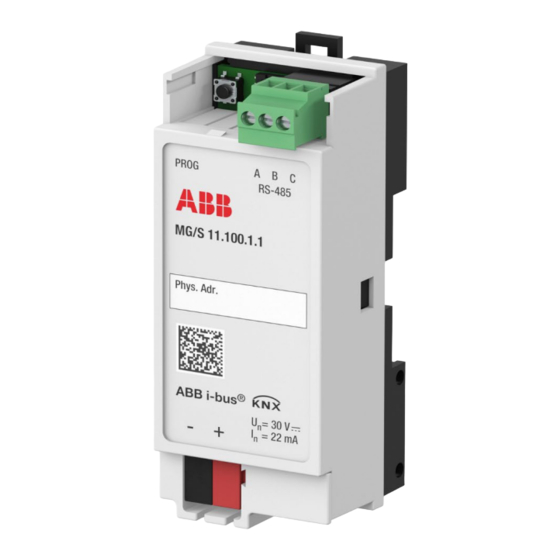
ABB i-bus ® Product overview MG/S 11.100.1.1 Modbus RTU – KNX TP Gateway, 100 Points Fig. 1: Device illustration, MG/S 11.100.1.1 Note about navigation in the PDF: Key combination Product Manual | EN | MG/S 11.100.1.1 | 9AKK108467A5941 Rev. B 9... -
Page 14: Dimension Drawing
ABB i-bus ® Product overview 3.5.1 Dimension drawing Fig. 2: Dimension drawing 10 9AKK108467A5941 Rev. B | MG/S 11.100.1.1 | EN | Product Manual Note about navigation in the PDF: Key combination 'Alt + left arrow' jumps to the previous view/page... -
Page 15: Connection Diagram
ABB i-bus ® Product overview 3.5.2 Connection diagram Fig. 3: Connection diagram Legend Labeling field KNX connection 2D code KNX programming button DIP switch RS-485 Modbus connection Power/Modbus activity LED (yellow) KNX programming LED (red) Note about navigation in the PDF: Key combination Product Manual | EN | MG/S 11.100.1.1 | 9AKK108467A5941 Rev. -
Page 16: Operating Controls And Display Elements
ABB i-bus ® Product overview 3.5.3 Operating controls and display elements Operating control/LED Description/function Display Assignment of the physical address LED on: Device in programming mode KNX programming button/LED LED flashing: Visual localization of the device Switching: ON: DIP switch x set to ON position... -
Page 17: Technical Data
ABB i-bus ® Product overview 3.5.4 Technical data 3.5.4.1 General technical data Device Dimensions 92 × 36 × 32 mm (H x W x D) Mounting width in space units 2 modules, 18 mm each Weight 0.048 kg Mounting position... -
Page 18: Device Type - Knx Interface
ABB i-bus ® Product overview 3.5.5 Device type – KNX interface Device type Modbus RTU – KNX TP Gateway 100 MG/S 11.100.1.1 Points Application Modbus RTU Gateway, 100p/... … = current version number of the application Maximum number of Group Objects... -
Page 19: Function
ABB i-bus ® Function Function Device functions The Modbus KNX Gateway is a compact modular installation device for the integration of Modbus RTU servers and KNX TP devices. The Modbus RTU – KNX TP Gateway is a bidirectional gateway with 100 freely configurable data points. -
Page 20: Device Configuration App (Dca)
DCA, the mapping of the Modbus KNX data points of a server can be exported as a reusable template. The DCA can also be used to import ready-made device templates from a database. The DCA "ABB MG/S11.100.1.1 Template Configuration" is available for download from the Shop. -
Page 21: Reaction After Bus Voltage Recovery
ABB i-bus ® Function 4.3.2 Reaction after bus voltage recovery Bus voltage recovery is the state that exists after the bus voltage is restored. After a bus voltage recovery, the device restarts and executes the following actions: Keeps the configuration parameters •... -
Page 23: Mounting And Installation
▶ Disconnect all phases before working on the electrical connection. The device can be mounted in any position as required on a 35 mm mounting rail. The connection to the bus (ABB i-bus ® KNX) is made using the bus connection terminal supplied. -
Page 24: Mounting On Mounting Rail
ABB i-bus ® Mounting and installation Mounting on mounting rail Fig. 4: Mounting on mounting rail Place the mounting rail holder on the upper edge of the mounting rail and push down. Pull down the lower latching lever with the aid of a screwdriver or similar tool. -
Page 25: Commissioning
You need to download the entire ETS application. Downloads may take longer after an application is uninstalled or when changing applications. Putting the device into operation Connect the device to the bus (ABB i-bus ® KNX). Switch on the bus voltage. -
Page 26: Assignment Of The Physical Address
ABB i-bus ® Commissioning Assignment of the physical address Note If it is set in ETS that the application is to be downloaded during programming, the download will begin after assignment of the physical address. Triggering assignment of the physical address via ETS: Press the Programming button. -
Page 27: Device Configuration App (Dca)
DCA, the mapping of the Modbus KNX data points of a server can be exported as a reusable template. The DCA can also be used to import ready-made device templates from a database. The DCA "ABB MG/S11.100.1.1 Template Configuration" is available for download from the Shop. -
Page 28: Export Device Templates
ABB i-bus ® Commissioning 6.6.1 Export Device Templates Servers are configured in the ETS application. Configurations can be exported as templates in .knxmbr file format. In the list, select the device (server) you wish to export. Select "Export". Specify a local storage location and click "Save". - Page 29 The connection to the database is made via an https website that uses Port 443. Please contact ABB if you have any further questions about the database. After importing the template from local storage or from the database, the following window appears: All the previously assigned data points from the imported template are listed.
-
Page 30: Edit Devices
ABB i-bus ® Commissioning 6.6.3 Edit Devices Click "Replace" to import a template into an existing device. Device name and data points are replaced by those of the template. Click "Delete" to delete the device from the ETS application. 26 9AKK108467A5941 Rev. B | MG/S 11.100.1.1 | EN | Product Manual... -
Page 31: Firmware Updates
Note The connection to the database is made via an https website that uses Port 443. Please contact ABB if you have any further questions about the database. Note about navigation in the PDF: Key combination Product Manual | EN | MG/S 11.100.1.1 | 9AKK108467A5941 Rev. B 27... -
Page 33: Parameters
ABB i-bus ® Parameters Parameters General Note ETS (Engineering Tool Software) is used to parameterize the device. The following sections describe the device parameters based on the parameter windows. The parameter windows have a dynamic design. The parameter windows are shown or hidden depending on the number of Modbus servers. -
Page 34: Parameter Windows
ABB i-bus ® Parameters Parameter windows 7.2.1 General parameter window The following settings can be made in this parameter window: • General settings for KNX General settings for Modbus • Fig. 5: General parameter window Prerequisites for visibility • The parameter window is always visible. -
Page 35: Read On Init Delay
ABB i-bus ® Parameters 7.2.1.1 Read On Init Delay This parameter is used to define the sending delay of the GroupValueRead telegram for Group Objects with an initialization flag "I". Note I flag: If the device is reset, a new GroupValueRead telegram is sent after the device restarts. The purpose of this is to call the object value via a GroupValueResponse. -
Page 36: In Operation
ABB i-bus ® Parameters 7.2.1.3 In Operation This parameter is used to enable the Group Object In Operation. Readiness can be monitored by another KNX device using this Group Object. If a telegram is not received, the sending device could be faulty or the bus cable to the transmitting device could be interrupted. -
Page 37: Baud Rate
ABB i-bus ® Parameters 7.2.1.5 Baud rate This parameter is used to define the transmission speed of the Modbus RTU interface. The baud rate specifies the symbol rate of the data transmission. The baud rate must be the same for all devices in the Modbus system (client and server). -
Page 38: Response Timeout
ABB i-bus ® Parameters 7.2.1.7 Response Timeout This parameter defines how many milliseconds the gateway waits between sending a request to a server and receiving a response. If the gateway receives a response before this time elapses, it resets the timer and continues polling. -
Page 39: Poll After Write
ABB i-bus ® Parameters 7.2.1.9 Poll After Write This parameter is used to activate the function Poll after write. Activating this allows the gateway to update the new status of the corresponding KNX Group Object immediately after a write command to a server. -
Page 40: Device X Name
ABB i-bus ® Parameters 7.2.1.11 Device x Name This parameter is used to specify an individual description for a device. Option Free text entry Maximum 64 ASCII characters; the maximum number of characters may vary for other character formats. Note This parameter appears in two places: •... -
Page 41: Device X Server Address
ABB i-bus ® Parameters 7.2.1.12 Device x Server Address This parameter is used to define the server address. Each Modbus server must be given a unique server address. The setting must be made on the server itself and must match this parameter. -
Page 42: Device X Number Of Data Points
ABB i-bus ® Parameters 7.2.1.13 Device x Number of Data Points This parameter is used to define the number of data points on the Modbus device concerned. Option 0 … 10 … 100 Note This parameter appears in two places: •... -
Page 43: Device X Active
ABB i-bus ® Parameters 7.2.1.14 Device x Active This parameter is used to define whether the device is activated. If the device is deactivated, all of its data points are automatically deactivated. Deactivated data points are taken into account in the Total Gateway Data Points parameter. -
Page 44: Config Device X Parameter Window
ABB i-bus ® Parameters 7.2.2 Config Device x parameter window Settings for the device are made in this parameter window. The visibility of the parameter window is dependent on the setting in the Number of Devices parameter. Fig. 6: Config Device x parameter window... -
Page 45: Device X Name
ABB i-bus ® Parameters 7.2.2.1 Device x Name This parameter is used to specify an individual description for a device. Option Free text entry Maximum 64 ASCII characters; the maximum number of characters may vary for other character formats. Note This parameter appears in two places: •... -
Page 46: Device X Server Address
ABB i-bus ® Parameters 7.2.2.2 Device x Server Address This parameter defines the server addresses. Each Modbus server must be given a unique server address. The setting must be made on the server itself and must match this parameter. Note Address duplication can cause conflicts. -
Page 47: Device X Number Of Data Points
ABB i-bus ® Parameters 7.2.2.3 Device x Number of Data Points This parameter is used to define the number of data points on the Modbus device concerned. Option 0 … 10 … 100 Note This parameter appears in two places: •... -
Page 48: Device X Active
ABB i-bus ® Parameters 7.2.2.4 Device x Active This parameter is used to define whether the device is activated. If the device is deactivated, all of its data points are automatically deactivated. Deactivated data points are taken into account in the Total Gateway Data Points parameter. -
Page 49: Device X Active" Checkbox
ABB i-bus ® Parameters 7.2.2.5 "Device x Active" checkbox This parameter is used to define whether the individual data point is activated. Deactivated data points are taken into account in the Total Gateway Data Points parameter. Option The data point is deactivated. -
Page 50: Dpt
ABB i-bus ® Parameters 7.2.2.7 This parameter defines the KNX data point types (DPT). For a description of all the data point types available in the ETS application, click here. The selected DPT is shown in the name of the corresponding Group Object. -
Page 51: Write Function
ABB i-bus ® Parameters 7.2.2.9 Write Function This parameter is used to define which Modbus function codes are selected. The function code tells the server which memory type (i.e. register, coils, etc.) to access and write. Option 5: Write Single Coil... -
Page 52: Format
ABB i-bus ® Parameters 7.2.2.11 Format This parameter is used to define the format of the Modbus register data. If the function code (Read or Write) refers to coils or discrete inputs, the format is automatically set to "–". The parameter can no longer be adjusted. The only situation where all options are available is for function codes referring to registers. -
Page 53: Register Address
ABB i-bus ® Parameters 7.2.2.13 Register Address This parameter is used to define the address of the register (DEC) in the server's memory range. Option 0 … 65535 Prerequisites for visibility • This parameter is in the Config Device x parameter window. -
Page 54: Bits
ABB i-bus ® Parameters 7.2.2.15 # Bits This parameter is used to define the number of specific bits in the assigned register. The options in the # Bits parameter are only adjustable when the Format:4: BitFields option is selected. Option 1 …x …... -
Page 55: Operation
ABB i-bus ® Parameters 7.2.2.17 Operation This parameter is used to define the mathematical operation. The options Multiply by and Divide by are arithmetical connections that are always available. For unidirectional data points (either the Read Function or the Write Function), there are also logical connections available. -
Page 57: Group Objects
ABB i-bus ® Group Objects Group Objects Overview of Group Objects Either one or two Group Objects are enabled per data point, depending on the option selected in the Read Function and Write Function parameters. Note If both the Read Function and Write Function are selected, ETS creates 2 Group Objects (one Status Group Object and one Control Group Object). -
Page 58: Knx Status Group Objects
Length Flags 1-active Status In Operation [1.011] 1.011 1 bit This Group Object cyclically sends an In operation telegram on the bus (ABB i-bus ® KNX). The sending cycle is set in parameter Sending cycle. Telegram value: • 1 = Active •... -
Page 59: Dx.x Control Group Objects
ABB i-bus ® Group Objects Dx.x Control Group Objects The Group Objects are shown in accordance with the specifications in the device settings table. Function Group Object name Data point type Length Flags KNX -> Modbus Dx.x Control Group Object x.xxx... -
Page 61: Operation
ABB i-bus ® Operation Operation Manual operation This section is not relevant for this device. Note about navigation in the PDF: Key combination Product Manual | EN | MG/S 11.100.1.1 | 9AKK108467A5941 Rev. B 57 'Alt + left arrow' jumps to the previous view/page... -
Page 63: Maintenance And Cleaning
ABB i-bus ® Maintenance and cleaning Maintenance and cleaning 10.1 Maintenance The device is maintenance-free if used properly. In the event of damage, e.g. during transport and/or storage, repairs are not allowed to be made. 10.2 Cleaning Disconnect the device from the electrical power supply before cleaning. -
Page 65: Removal And Disposal
ABB i-bus ® Removal and disposal Removal and disposal 11.1 Removal Fig. 7: Removing from the mounting rail Press on the top of the device. To release the device, pull down the latching lever with the aid of a screwdriver. -
Page 66: Environment
ABB i-bus ® Removal and disposal 11.2 Environment Consider environmental protection. Electrical and electronic devices must not be disposed of as domestic waste. The device contains valuable resources that can be recycled. Therefore, please take the device to a suitable recycling center. All packaging materials and devices are provided with markings and test seals for proper disposal. -
Page 67: Planning And Application
EOL resistor RT (T=Termination). Client = Level Converter (e.g. MG/S 11.100.1.1 Modbus KNX Gateway) Server = Modbus RTU device (e.g. ABB electricity meter from the A and B series, water meter, heat meter, gas meter, etc., with Modbus RTU interface). -
Page 68: Polarity
ABB i-bus ® Planning and application 12.2.4 Polarity Attention must be paid to the correct polarity of the core pairs during installation because incorrect polarity will invert the data signals. Particularly if there are difficulties in relation to the installation of new devices, any troubleshooting should start with a check on the bus polarity. -
Page 69: Troubleshooting
ABB i-bus ® Planning and application 12.2.9 Troubleshooting To minimize potential sources of error, there are certain principles you should follow: Installation: • Check cable length, polarity, termination resistors, etc. Configuration: The server manual is available. • • The baud rate and parity must be the same for all the devices in the Modbus system. -
Page 71: Appendix
ABB i-bus ® Appendix Appendix 13.1 Scope of delivery The device is supplied together with the following components: 1 x Modbus RTU – KNX TP Gateway, MG/S 11.100.1.1 • • 1 x installation and operating instructions Note about navigation in the PDF: Key combination Product Manual | EN | MG/S 11.100.1.1 | 9AKK108467A5941 Rev. -
Page 72: Status Byte Device
ABB i-bus ® Appendix 13.2 Status byte Device This section is not relevant for this device. 68 9AKK108467A5941 Rev. B | MG/S 11.100.1.1 | EN | Product Manual Note about navigation in the PDF: Key combination 'Alt + left arrow' jumps to the previous view/page... - Page 74 — © Copyright 2023 ABB. We reserve the right to make technical changes to the products as well as amendments to the content of this document at any time without advance notice. In the case of orders, the respective agreed conditions shall be decisive.
Need help?
Do you have a question about the i-bus KNX MG/S 11.100.1.1 and is the answer not in the manual?
Questions and answers