Table of Contents
Advertisement
Quick Links
Advertisement
Chapters
Table of Contents

Related Manuals for Syn-Tech Systems FuelMaster FMU-2500 Classic

Summary of Contents for Syn-Tech Systems FuelMaster FMU-2500 Classic
- Page 1 Fuel Management Unit (FMU) Installation Manual FMU-2500, 3000, 3500, Classic and Plus, Commercial and DoD 24 May 2013 SYN-TECH SYSTEMS, INC. 100 Four Points Way Tallahassee FL 32305 800-888-9136 Toll Free 850-878-2558 850-877-9327 Fax www.myfuelmaster.com...
- Page 2 ADDENDUM The following necessary changes/additions to the Fuel Management Unit (FMU) Installation Manual dated 24 May 2013 have been identified. Insert this Addendum inside the manual title page. Changed text is in italics. Location of the change/addition is identified in the manual with a checkmark .
- Page 3 ‐ Install FMU Upper Cabinet . See Figure 4 26a. Installation of the FMU Upper Cabinet should be delayed until it is necessary to complete the installation. If desired, the FMU Upper Cabinet may be rotated 180 degrees before installation to accommodate situations where the FMU pedestal door needs to open from the reverse side of the FMU (such as in a kiosk mount).
- Page 4 ‐ 4. Position the Upper Cabinet on the Pedestal. Support the Upper Cabinet and insert the ¼ 20 x ¾ attach screws through the attach holes in the underside of the top flange of the Pedestal, through the holes in the Upper Cabinet, and thread into the nutserts in the Cable Interface Plate.
-
Page 5: Table Of Contents
FuelMaster Installation Manual ® Table of Contents Introduction ......................11 Proprietary Information ....................11 Trademark Acknowledgements ..................11 Purpose ........................... 11 Section/Appendix Layout ....................11 Section 1 - General Information ................13 Introduction ........................13 Safety Precautions ......................13 References ....................13 Safety Guidelines .................. - Page 6 FuelMaster Installation Manual ® Table of Contents (con’t) Solid State Relay Assemblies .............. 28 Dual Control Relay Assemblies ............28 Automatic/Manual Mode Switch Differences ......... 28 Prokee ® ................................Smartcards ....................29 Fuel Management Software ................29 Central Controller ..................29 Prokee /Smartcard Encoder ................
- Page 7 FuelMaster Installation Manual ® Table of Contents (con’t) Section 3 - Site Planning and Preparation ............37 Introduction ........................37 FMU Dimensions ......................37 EIU Dimensions ....................... 37 Conduit Requirements ..................... 41 Conduit Size ....................41 Conduit Fill Capacity ..................41 Conduit Applications ..................
- Page 8 FuelMaster Installation Manual ® Table of Contents (con’t) Resistors ....................54 Pulsers ......................54 Pulse Filtering ..................55 Dual Output Pulsers ................55 Opto-Isolators ..................56 Quick Stop Button ..................56 Data Logger/On-Site Printer ................. 57 Tank Monitor Interface ................. 57 Satellite/EIU Communications ..............
- Page 9 FuelMaster Installation Manual ® Table of Contents (con’t) Dispenser Hose Control ..............71 Dispenser Pulse ................. 71 Satellite/EIU Communications ............71 Tank Monitor ..................71 Indoor Receipt Printer ................ 71 Wire/Cable Connections at FMU ..............72 1.A/C Power .................... 72 2.Telephone/Two-Way Ringdown Device ..........
- Page 10 FuelMaster Installation Manual ® Table of Contents (con’t) Wire Connections at Accessory Controller ............ 113 Configure Master FMU for EIU ..............113 Section 5 – Initialization ..................115 Software Installation and Setup ..................115 Configure Master FMU for EIU Operation ................ 116 Post Installation Inspection and Test ................
- Page 11 FuelMaster Installation Manual ® Appendices (con’t) Appendix E – Retail Applications ................149 Appendix F – Wiring Differences for Canadian and European Certified FMUs ..............177 Appendix G – FMU Wire and Cable Connection Points .......... 179 Appendix H – Electronic Dispenser Interface ............181 Figures and Tables Figure 1-1.
- Page 12 Figure 4-34. EIU Wiring ......................... 110 Figure 4-35. Connecting Wire Harnesses ..................111 Attachments Acceptance Test Procedure (ATP) for Upgrades and Installations of FuelMaster Fuel ® Management Units (back of manual; tear out, complete and return to Syn-Tech Systems, Inc., in provided self-addressed, postage-paid envelope)
-
Page 13: Introduction
Use of a term in this manual should not be regarded as affecting the validity of any trademark. All other trademarks are acknowledged. Purpose This manual provides installation instructions for the Syn-Tech Systems, Inc., FuelMaster Fuel ® Management Unit (FMU) for fixed fueling sites. These instructions have been prepared for use by technicians who are qualified to complete electrical work in hazardous locations. -
Page 14: Appendix F - Wiring Differences For Canadian And
FuelMaster Installation Manual ® Section 2 - System Description This section contains a description of all FuelMaster standard and optional equipment ® available at the time of publication of this manual. Section 3 – Site Planning and Preparation This section provides guidelines for preparing your site for a FuelMaster installation. -
Page 15: Section 1 - General Information
® small service stations to large-scale fleet operations, including retail sales. The FMUs (Fuel Management Units) and Fuel Management Software are encoded by Syn-Tech Systems with matching system designators (site signatures) to assure security and allow access only by the customer to which the system designator is assigned. -
Page 16: Safety Guidelines
FuelMaster Installation Manual ® • NFPA Handbook 407, Standard for Aircraft Fuel Servicing, provides minimum fire safety requirements for procedures, equipment, and installations during ground fuel servicing of aircraft using liquid petroleum fuels. Knowledge of this reference is necessary when performing an installation in support of aircraft fuel servicing. -
Page 17: Protecting Against Electrostatic Discharge
FuelMaster Installation Manual ® • Disconnect your FMU and devices from their sources. Also disconnect any telephone or telecommunication lines from the FMU to reduce the potential for personal injury or shock. • Wear a wrist grounding strap or touch an unpainted metal surface on the chassis, such as the back panel, before touching anything inside your FMU. -
Page 18: Certifications/Approvals
A Hold Harmless Agreement is attached to this manual, and requested to be signed by the using customer. This agreement references the potential hazards associated with wireless network security, and serves to remove liability from the seller (Syn-Tech Systems or its distributors) when wireless networking equipment is installed for communications to the FMU. -
Page 19: Figure 1-2. Fmu Electrical Safety Spacing
FuelMaster Installation Manual ® intrinsically safe or must be enclosed within an explosion-proof enclosure. Intrinsically safe devices are generally limited to very low voltage and low current devices, such as that portion of a pulser before the barrier. Examples of explosion-proof enclosures are rigid metal conduit, and junction boxes and conduit fittings approved for use in hazardous locations. -
Page 20: Figure 1-3. Fmu Id Plates
FuelMaster Installation Manual ® Figure 1-3. FMU ID Plates... -
Page 21: Id Plates
FuelMaster Installation Manual ® Syn-Tech received notification of PCI compliance in May 2009. If it is desired to validate compliance through the PCI Security Standards Council website, go to Validated Payment Applications and search on Syntech-Fuelmaster. FuelMaster has also been certified by the National Conference on Weights and Measures, and has ®... -
Page 22: Basic Fuelmaster Fmu Warranty
Additionally, associated equipment including printers, personal computers, and other items not manufactured by Syn-Tech Systems, Inc. are warranted only to the extent covered by the original manufacturer. Additionally, this warranty is limited to approved locations (generally the continental United States) and is not transferable except by written permission of Syn-Tech Systems, Inc. -
Page 23: Figure 1-4. Sample Fmu Initialization Form
FuelMaster Installation Manual ® Figure 1-4. Sample FMU Initialization Form... -
Page 24: Fuelmaster ® Equipment Specifications
FuelMaster Installation Manual ® FuelMaster Equipment Specifications ® Rated Supply Voltage Limits 120VAC +/- 15% (upper limit) 75 +/- 10% (lower limit) Rated Supply Frequency 50 or 60 Hz Rated Supply Current 2.4 amps Max operating Heaters (2 each) 1.0 amps (each) Other electronics 0.4 amps Operating Altitude, Max... -
Page 25: Battery Reference
FuelMaster Installation Manual ® Battery Reference There are batteries on the mainboard, card reader board, and data logger. The Plus mainboard and data logger use a battery with Syn-Tech part number 243736. The classic mainboard and card reader board use a battery with Syn-Tech part number 180181. -
Page 26: Parts Substitution And Modification
When these products are purchased from Syn-Tech Systems, the manufacturer’s warranty is honored and administered by Syn-Tech Systems. Support Syn-Tech Systems strives to provide the best customer and distributor support possible. Free on-site distributor and customer training is provided quarterly (or more often as needed) at the FuelMaster factory in ®... -
Page 27: Section 2 - System Description
FuelMaster Installation Manual ® Section 2 System Description Introduction Components . The FuelMaster Fuel Management System consists of equipment designed to ® automate control and accountability of any metered liquid or gas. It is not limited only to fuels applications. The base system contains all equipment necessary to accomplish these tasks and consists of: •... -
Page 28: Figure 2-1. Fuel Management Unit (Fmu)
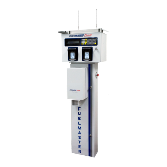
FuelMaster Installation Manual ® Figure 2-1. Fuel Management Unit (FMU) -
Page 29: Automatic/Manual (Bypass) Operation
FuelMaster Installation Manual ® All current versions of the standard FMU are delivered with an alpha-numeric keypad, a 33.6k baud modem, a Type II compact flash memory card (for current and future memory requirements), weatherproof Prokee , Smartcard, and/or magnetic stripe card receptacles, and a backlit display ®... -
Page 30: Relay Options
FuelMaster Installation Manual ® Relay Options . An FMU may be thought of as a switch installed in a control circuit of a dispensing device. It is installed where it can interrupt flow to each dispensing hose. When authorization is provided, the FMU “closes the switch” to complete the circuit. Relays are used to “close the switch”. -
Page 31: Smartcards
FuelMaster Installation Manual ® • User Keys are encoded with a user identification number and are assigned to a user • Supervisor Keys are authorized special access to reconfigure the FMU, run built-in tests of the FMU, issue fuel to operators without a Prokee®, and enter inventory-tracking information. •... -
Page 32: Prokee ® /Smartcard Encoder
A thorough explanation of AIM is covered in the AIM2™ Installation Manual. Americans with Disabilities Act (ADA): Syn-Tech Systems has provided and installed shortened FMUs for compliance with the requirements of the Americans with Disabilities Act. If you have a need for an FMU with ADA compliance, speak to your distributor or FuelMaster Regional ®... -
Page 33: Data Logger
FuelMaster Installation Manual ® Data Logger: the Data Logger is an accessory circuit board that plugs into one of the mainboard expansion slots, and captures the print text normally sent to a Transaction Printer. The Data Logger captures the print text on a socketed SD (Secure Digital) memory card. The SD card provided with the system has a 1 GB capacity and provides storage for over 900,000 transactions and messages. -
Page 34: Equipment Interface Unit (Eiu)
FuelMaster Installation Manual ® through this communications connection to initiate CPU actions. For these dispensers, an Electronic Dispenser Interface must be installed between the FMU and dispenser distribution box. See Appendix H for details on the use of the Electronic Dispenser Interface. Equipment Interface Unit (EIU) n EIU (Figure 2-5) is a low-cost Satellite FMU installed to control activation of ancillary fuel site equipment (i.e., gate opener, door opener, car wash, vacuum... -
Page 35: Otr (Over The Road)
FuelMaster Installation Manual ® OTR (Over the Road): OTR is a software/firmware option used by trucking fleets. Its primary use is to provide for one Prokee or Smartcard to record transactions for refrigeration (reefer) units in ® addition to the parent truck. Proximity Card Reader : a Proximity Card Reader is available for installation in an FMU for reading 26 or 34 bit proximity cards. -
Page 36: Satellite Fmus
FuelMaster Installation Manual ® with RS-422, and step down to an RS-232 termination at a printer or tank monitor. When used in pairs, the converter may function as a short haul modem to extend the working length of an RS-232 printer cable. -
Page 37: Telephone Line Extender
Transaction printers purchased from Syn-Tech Systems include a 25 or 50 foot serial cable with an attached DB-25 connector, and printer surge protection. The cable or surge protection may also be purchased separately. - Page 38 FuelMaster Installation Manual ®...
- Page 39 FuelMaster Installation Manual ® Section 3 Site Planning and Preparation Introduction This section includes considerations which must be given to planning and preparation for FuelMaster ® servicing and Central Accounting Office sites. Each servicing site identified in the Fuel Management Software will contain, as a minimum, one master FMU, one product dispenser, and one product tank.
-
Page 40: Figure 3-1. Fmu Dimensions (In Inches)
FuelMaster Installation Manual ® Figure 3-1. FMU Dimensions (in inches) (Full-size FMU) -
Page 41: Figure 3-2. Fmu Dimensions (In Inches) Americans With Disabilities Act (Adc) Fmu
FuelMaster Installation Manual ® Figure 3-2. FMU Dimensions (in inches) Americans with Disabilities Act (ADA) FMU... -
Page 42: Figure 3-3. Eiu Dimensions (In Inches)
FuelMaster Installation Manual ® Figure 3-3. EIU Dimensions (in inches) Figure 3-3 does not illustrate the interface between the EIU pedestal and EIU cabinet. From the rear of the EIU pedestal to the rear of the EIU cabinet is 4-1/4 inches. Overall front to rear distance including the extension of the visor over the Prokee receptacle is 11-5/8 inches. - Page 43 National Electric Codes (NEC), NFPA 70. This is a common requirement among reputable manufacturers of fuel management systems. If it is not possible to comply with the requirement for rigid metal conduit, contact Syn-Tech Systems. Acceptable workarounds may be available.
- Page 44 FuelMaster Installation Manual ® Conduit Applications . See Figure 3-4 for a sample site layout containing a Master FMU on one island, a Satellite FMU on another island, an oil dispenser on a third island, and an EIU and gate controller on a fourth island.
-
Page 45: Figure 3-4. Sample Site Layout
FuelMaster Installation Manual ® Figure 3-4. Sample Site Layout (Mechanical Dispensers) - Page 46 FuelMaster Installation Manual ® Servicing Site Requirements NOTE Sites may be arranged with any combination of one Master FMU and up to eight Satellite FMUs (including EIUs). Master FMUs and Satellite FMUs can control up to eight hoses each. EIUs can control one ancillary equipment item (door/gate opener, car wash, etc.) each.
- Page 47 Standard Protection : every FMU is provided with protection against surges from incoming power and telephone lines. Optional transaction printers purchased from Syn-Tech Systems are also provided with surge protection against surges which may enter through the input cable from the FMU.
- Page 48 FuelMaster Installation Manual ® Available options for communications with the Central Controller include: a) by phone, b) by network, or c) by direct connect to a master FMU with a laptop. FMU and Central Controller communications are not continually active. Except for credit card authorization from the FMU, connection must be initiated by the Central Controller operator.
- Page 49 FuelMaster Installation Manual ® Since it does not use an active analog phone line, installation of a two-way ringdown device may preclude support from Syn-Tech’s Customer Satisfaction Center if the device is not positioned close to an analog phone jack. Typically the two-way ringdown device is positioned close to the analog phone jack used by the fax machine.
- Page 50 Additional hose controls are optional. Syn-Tech Systems will not dictate a control method which must be used for all situations. Instead, the pros/cons of each control method will be explained so the installer and customer may select the control method that best suits the application.
- Page 51 FuelMaster Installation Manual ® for dispenser control circuits. The FMU does not provide power for the device being controlled. It switches existing power. The FMU installer must find a circuit in the dispenser that interrupts the flow of fuel. This may be an interruption of power to the dispenser reset mechanism, or a solenoid valve, or a pump motor.
- Page 52 FuelMaster Installation Manual ® detection. Pump handle detection settings differ between FuelMaster classic and Plus FMUs. Pump ® handle detection in DoD systems functions the same as in classic systems. In classic and DoD systems, pump handle detection has two settings, YES and NO. When set to YES, detection must be present when the handle is turned on and must go away when the pump handle is turned off.
- Page 53 FuelMaster Installation Manual ® When it is not possible to make a YES, START ONLY, or START AND END pump handle detect setting to remove unwanted pulses during reset, other options may be used to achieve the same results. Pulsers such as the Integrated Control Systems (ICS) SP1 110 VAC pulser, or OPW Model 500 with 110 VAC switching circuits in them will not allow pulses to return to the FMU until an authorization signal is sent to the dispenser.
- Page 54 FuelMaster Installation Manual ® autorisées ne seront pas pris en compte. Fuel dispensers and dispensing systems are designed to internally control fuel flow and turn on or off pump motors. One of the easiest and safest control methods is control of dispenser reset power. This method controls the input of power to the dispenser so nothing can happen within the dispenser until authorization is received from the FMU.
- Page 55 FuelMaster Installation Manual ® dispenser is being controlled, there will be a single pump motor. If you wired an output from LD1 and LD2 to a single pump motor, and started a transaction by selecting only hose 1, the output from LD1 to the pump motor would backfeed to LD2 and authorize hose 2.
- Page 56 FuelMaster Installation Manual ® RC Networks (Snubbers/Spark Quenchers). There are wiring situations which may provide the FMU false indications of pump handle detection. RC networks may be used to remove these false indications. RC networks are a small cube shaped device with two wires leading into it. Most of these false indications occur with the use of solid state relays in the FMU.
- Page 57 FuelMaster Installation Manual ® Pulsers may provide quantity information in common increments referred to as divide rates. The most common divide rates are: 1:1 (one pulse per gallon), 10:1 (10 pulses per gallon), and 100:1 (100 pulses per gallon). The unit of measure may be something other than gallons. The FMU and FuelMaster ®...
- Page 58 Depressing the red mushroom-shaped button removes power. Turning the button clockwise 1/8 turn resets power. When purchased preinstalled from Syn-Tech Systems, the Quick Stop Button is installed on the FMU pedestal approximately 14 inches above the ID plate.
- Page 59 FuelMaster Installation Manual ® Data Logger/On-Site Printer NOTE • Data Logger and On-Site Printer connections must be made to a Master FMU. • The NEC states, “Communication conductors shall not be placed in any raceway, compartment, outlet box, junction box, or similar fitting with conductors of electric light, power, Class 1, non-power- limited fire alarm or medium power network-powered broadband communications circuits.”...
- Page 60 FuelMaster Installation Manual ® FuelMaster ® Communications to a TMU may originate in a Master FMU with either RS-232 or RS-422 communications. If the TMU is located beyond the range of RS-232 communications, and the TMU will not accept an RS-422 input, an RS-422 cable may be routed from the Master FMU to the TMU control box, then an RS-422 to RS- 232 converter can be used to step the RS-422 signal down to RS-232.
-
Page 61: Figure 3-5. Satellite Option Installation
FuelMaster Installation Manual ® Temporary Conversion of Satellite FMU to Master FMU: should a master FMU become unserviceable (other than DoD), all connected satellite FMUs will also become unserviceable. Operation of a satellite FMU may be restored by temporarily converting it to a master FMU. This may be done by 1) moving a serviceable modem (or network card) from the master FMU to the satellite FMU, 2) routing a temporary communications link (phone line or network cable) to the satellite FMU, then 3) sending the applicable authorization list to the converted satellite FMU from the Central Controller. - Page 62 FuelMaster Installation Manual ® operators may roll down a window and activate it without leaving the vehicle (like a drive-thru ATM). Like the FMUs,the option to input P.I.N. numbers may also be selected. EIUs have a red LED over the Prokee receptacle.
- Page 63 FuelMaster Installation Manual ® equipment should be located where it can be easily accessed without interfering with other daily duties of office personnel. The computer workstation should have access to AC power receptacles and a compatible communications medium for communications with the FMUs. Refer to the FuelMaster Plus User Manual for minimum PC requirements, and installation and operation ®...
- Page 64 FuelMaster Installation Manual ® Wireless Phone Lines: wireless phone line connections should only be considered when other mediums are not an option. Digital cell modem communications between analog devices is not reliable. Phone line extenders are considerably more expensive than wireless networking equipment, but may be considerably cheaper than trenching to install conduit.
- Page 65 The Central Controller contains transaction and database information peculiar to each customer that cannot be duplicated by Syn-Tech Systems. Loss of this information will eliminate all stored transaction and inventory data, and require manual input of all database information and re-encoding of each Prokee or Smartcard.
- Page 66 FuelMaster Installation Manual ®...
- Page 67 If anything is not correct, it should be noted and corrected before the installation proceeds. Contact Syn-Tech Systems’ Customer Satisfaction Center (800-888-9136, ext. 1500) as soon as possible if any damage is noted or anything is missing.
- Page 68 FuelMaster Installation Manual ® Central Controller Installation For the purposes of this manual, Central Controller installation includes only hardware installation. The FuelMaster Plus User Manual must be referred to for software setup and operation. ® Positioning the Central Controller NOTE The Central Controller need not be a desktop PC.
-
Page 69: Figure 4-1. Two-Way Ringdown Device Connection
FuelMaster Installation Manual ® Connecting a Two-Way Ring-Down Device If a Two-Way Ring-Down Device is to be used, see Figure 4-1 and position the Two-Way Ringdown Device where the necessary connections may be made. A two conductor communications cable from the FMU must be routed to the Two-Way Ringdown Device, then an RJ-11 jack must be installed on the end of the communications cable for connection into the Device. - Page 70 FuelMaster Installation Manual ® of the pedestal and the kiosk wall to permit removal of the screws that retain the relay assemblies and Pedestal I/O Board. The FMU pedestal will not always be mounted directly over conduit. Figure 4-3 illustrates some alternate mounting methods.
-
Page 71: Figure 4-2. Fmu Footprint (In Inches)
FuelMaster Installation Manual ® Figure 4-2. FMU Footprint (in inches) Figure 4-3. Alternate Mounting Methods ... - Page 72 FuelMaster Installation Manual ® 3. Drill screw anchor holes for all four corners of the pedestal, then seat the screw anchors. NOTE Screw anchor nuts may be left loose in step 4 to assist with the installation of conduit or liquid-tight flex up to the FMU pedestal electrical access panel.
- Page 73 FuelMaster Installation Manual ® Wire/Cable Recommendations. Where wire/cable sizes are listed, larger conductors may be used to gain additional range: AC Power to FMU(s). Three conductors; 12 AWG THHN (increase to 10 AWG if length exceeds 400 feet) stranded; black for hot, white for neutral, green for ground; should be derived from separate 15 amp circuit breaker.
- Page 74 FuelMaster Installation Manual ® Wire/Cable Connections at FMU Make the following wire/cable connections at the FMU: NOTE Many wire/cable connections are made to Phoenix-style pluggable printed circuit board connectors with terminals closed by turning a screw. Continuity will not exist if insulation is not stripped from the wires before insertion into the terminal.
-
Page 75: Figure 4-4. Ac Power And Phone Connections
FuelMaster Installation Manual ® Figure 4-4. AC Power and Phone Connections Figure 4-5. AC Power and Phone Connections (from reverse side of Surge Panel) ... -
Page 76: Figure 4-6. Network Cable Connection
FuelMaster Installation Manual ® Figure 4-6. Network Cable Connection 5. Quick Stop Button as Auxiliary Emergency Stop Switch. The Quick Stop Button has two terminals to receive wire connections. It removes power by depressing the red mushroom-shaped button. Power is restored by turning the button clockwise a partial turn until it pops back out to the reset position. - Page 77 1 stop bit. Serial connections are sometimes optional when purchasing printers. Ensure the printer being purchased has a serial connection. If the transaction printer is purchased from Syn-Tech Systems, Inc, it is preconfigured to the correct communications parameters, and a surge protector and interfacing cable are provided. The surge protector (part number 201421) and interfacing cable (part number 201669) may be purchased separately by addressing the applicable part number.
- Page 78 FuelMaster Installation Manual ® There are several options for dispenser control. It’s important to remember the FMU is not a power source. It should be treated as a switching device with the Pedestal I/O Board LN and LD positions acting as the switch contacts: LN being incoming power, and LD being outgoing authorization power. Look for a circuit in the dispensing equipment that may be interrupted by the addition of a “switch”...
-
Page 79: Figure 4-7. Pedestal I/O Board
FuelMaster Installation Manual ® Figure 4-7. Pedestal I/O Board ... - Page 80 FuelMaster Installation Manual ® WARNING Each dispensing device must be provided with a means to remove all external voltage sources during periods of maintenance and service of the dispensing equipment. Ref: NFPA 70 (2008 edition), para 514.13. When two or more dispensers utilize the same STP (submersible turbine pump) control relay/contact starter, power supplied by one dispenser to activate a control relay must be isolated to prevent feed back to another dispenser.
-
Page 81: Figure 4-8. Wiring Diagram - Controlling Reset
FuelMaster Installation Manual ® Figure 4-8. Wiring Diagram - Controlling Reset ... -
Page 82: Figure 4-9. Wiring Diagram - Controlling Reset In Dual Hose Single
FuelMaster Installation Manual ® Figure 4-9. Wiring Diagram - Controlling Reset in Dual Hose Single Product Dispenser without Backfeed (One Solution) b. Controlling Motors. See Figure 4-10. When controlling a classic or DoD FMU, and pump handle detection is needed, the control method most likely used will be controlling motors or solenoid valves. -
Page 83: Figure 4-10. Wiring Diagram - Controlling Motors
FuelMaster Installation Manual ® Figure 4-10. Wiring Diagram - Controlling Motors If the dispenser is being fed from the top of an aboveground tank, there must be an anti-siphon valve on the tank, or inline between the dispenser and tank. Without an anti-siphon valve, the siphon effect created when a previous transaction was performed will permit fuel to siphon through the dispenser and pump motor to the dispenser nozzle after the pump motor is turned off. - Page 84 FuelMaster Installation Manual ® Perform the following to control motors: 1) Inside the dispenser junction box, locate the wire feeding the pump motor for hose 1. It is most likely a red or orange wire from the dispenser reset mechanism wire-nutted to one of the motor leads (or contact starter).
-
Page 85: Figure 4-11. Wiring Diagram - Controlling Solenoid Valves
FuelMaster Installation Manual ® Figure 4-11. Wiring Diagram – Controlling Solenoid Valves Perform the following to control solenoid valves: 1) Inside the dispenser junction box, locate the RESET COMPLETE wire feeding the solenoid valve for hose 1. It is most likely an orange wire from the dispenser reset mechanism wire- nutted to an AC input to the solenoid valve. -
Page 86: Figure 4-12. Wiring Diagram - Using Dual Control Relay Assembly (Dcra) To Control Two Devices
FuelMaster Installation Manual ® Repeat steps 1 through 7, as required, for all additional hoses. Figure 4-12. Wiring Diagram - Using Dual Control Relay Assembly (DCRA) to Control Two Devices d. Using Dual Control Relay Assembly (DCRA) to Control Two Devices. See Figure 4-12. Classic and DoD FMUs do not provide for control of dispenser reset while also providing pump handle detection. - Page 87 FuelMaster Installation Manual ® If 50 amp solid state relay assemblies (SSRA) were used to control the two solenoid valves and one SUBMERSIBLE STARTER (or a single anti-siphon valve), LD1 and LD2 would be tied together either with a jumper, or at the SUBMERSIBLE STARTER. This wouldn’t work as an authorization signal would activate both solenoid valves when only one was authorized.
-
Page 88: Figure 4-13. Wiring Diagram - Two-Stage Valve Control
FuelMaster Installation Manual ® Figure 4-13. Wiring Diagram – Two-Stage Valve Control Preset quantities or costs may only be set with credit card transactions. The transaction is started with both the fast and slow valves turned on. When the setpoint is reached, the fast valve shuts off and the transaction is finished on the slow valve. - Page 89 FuelMaster Installation Manual ® The relay assemblies may be 50 amp solid state or dual control, and they may be mixed (one 50 amp solid state, and one dual control relay assembly). Unless otherwise requested, all FMUs built for small airport or marina applications have two dual control relay assemblies installed. This control method does not prevent dispenser reset and pump motor activation before authorization.
- Page 90 FuelMaster Installation Manual ® Controlling DC Devices (Hose Reels in Lube Bays/Bulk Oil Dispensers). NOTE Whenever a part is field modified, mark/label it to inform others of the modification so a replacement part may be modified in the same manner. Make Syn-Tech aware of the modification when ordering a replacement part.
-
Page 91: Figure 4-14. Location Of 75K Ohm Pump Handle Detect Resistors
FuelMaster Installation Manual ® Figure 4-14. Location of 75K ohm Pump Handle Detect Resistors g. Controlling Carwashes, Gate Openers. Carwashes and gate openers may be controlled by simple contact closure switching, but do not have pulse emitters. Under normal operating conditions, if an FMU provides an authorization signal but does not receive pulses, it will shut the hose position down through Zero Quantity Transaction Limits, a safety feature built into the FMU to prevent continual authorization when no pulses are received. - Page 92 FuelMaster Installation Manual ® requires a 15 second momentary, set the Pump Finish Timer to 15 seconds. Because only one pulse is being generated when one of these transactions is recorded, the divide rate must be set to 1:1. Pump handle detection should be set to NO or NONE. Repeat these settings for each FMU hose position used.
-
Page 93: Figure 4-15. Generating Pulse With Dual Control Relay Assembly
FuelMaster Installation Manual ® Figure 4-15. Generating Pulse with Dual Control Relay Assembly Figure 4-16. Generating Pulse with Solid State Relay Assembly ... - Page 94 FuelMaster Installation Manual ® 2) Using a Smart Relay Assembly. The Smart Relay Assembly (see Figure 4-17) is so named because of its ability to be programmed to perform multiple functions not possible with simple wiring workarounds. It has a Programmable Interface Controller (PIC) which may be programmed to perform multiple functions.
-
Page 95: Figure 4-17. Smart Relay Assembly
FuelMaster Installation Manual ® J4 on Pedestal I/O Used Board Satellite I/O Control Board PRB1 or PRB2 Indicator Indicator Lights Lights (L1,L2,L3, L4) (K1,K2,K3,K4) Programmable Relays Interface (4 places) Controller (PIC) Used Switches Auto/ Manual Control Wiring Switches Inputs (4 places) Figure 4-17. - Page 96 FuelMaster Installation Manual ® h. Monitor Mode. There are applications which may require FuelMaster to continuously monitor ® the flow of fuel, but not through individual transactions. Such would be the flow of fuel to a furnace or some other device which is continually operating. One application uses it to monitor the continuing flow of water and glycol into a deicing fluid blender.
- Page 97 FuelMaster Installation Manual ® switch detection. The +12V and 0V positions are not tied to a specific P_ position. Any +12V or 0V position may be used with any P_ position. Since there is only one 0V position for every two P_ positions, two conductors must be connected to each 0V position when 0V connections are required.
-
Page 98: Figure 4-18. Connecting To Veeder-Root 1871 Pulser
FuelMaster Installation Manual ® Figure 4-18. Connecting to Veeder-Root 1871 Pulser Figure 4-19. Connecting to Veeder-Root 7671 Pulser Figure 4-20. Connecting to ICS 12VDC Pulsers ... -
Page 99: Figure 4-21. Connecting To Ics 110 Vac Pulsers
FuelMaster Installation Manual ® Figure 4-21. Connecting to ICS 110 VAC Pulsers Figure 4-22. Connecting to OPW 12 VDC Pulsers Figure 4-23. Connecting to OPW 110 VAC Pulsers ... -
Page 100: Figure 4-24. Connecting To Open Collector Pulser (Gasboy 9800 Pump I/F Shown)
FuelMaster Installation Manual ® Figure 4-24. Connecting to Open Collector Pulser (Gasboy 9800 Pump I/F shown) Figure 4-25. Removing Counts During Reset b. Dual Output Pulsers. Pulsers are available with dual outputs; pulsers which provide outputs to two different devices such as an FMU and a tank monitor. An application which may require a dual output pulser is a system having both an FMU and a TLS-350R Veeder-Root tank monitor. - Page 101 The NEC allows for this and specifies the requirement for cable insulation in NFPA 70, para 522.24(A). Syn-Tech Systems further specifies the pulser cable be shielded. Bleedover from AC control wires to DC pulser wires should not occur when these conditions are met. If it...
-
Page 102: Figure 4-26. Redundant Fmus, One Dispenser, One Pulser
FuelMaster Installation Manual ® Figure 4-26. Redundant FMUs, One Dispenser, One Pulser NOTE If two FMUs are receiving pulses from one pulser, the PULSE FILTERING dip switches must be set the same in both FMUs or quantity variations will show between the two FMUs. If two FMUs are receiving pulses from one pulser, the PULSE FILTERING dip switches must be set the same, or quantity variations will show between the two FMUs. -
Page 103: Figure 4-27. I/O Silver Board
FuelMaster Installation Manual ® Figure 4-27. I/O Silver Board Index Description Satellite Position Number Electronic Dispenser Interface or Indoor Receipt Printer Ribbon Cable Connector, JP12 (see Note) Electronic Dispenser Interface or Indoor Receipt Printer RS-232 Connector, JP11 (see Note) Attach Screws Over Standoffs (6 places) ... -
Page 104: Figure 4-28. Satellite I/O Control Board
FuelMaster Installation Manual ® Figure 4-28. Satellite I/O Control Board Index Description Index Description Mainboard Connector (J1) TANK MONITOR (J4) Attach Screws (7 places) SATELLITE CONNECTORS (J5/J6) Board Revision Level PULSE FILTERING (DS1) SATELLITES INSTALLED JUMPERS (S1) Ribbon cable to Pedestal I/O Board (J7) TMU SELECT JUMPERS (S2/S3) Ribbon cable to Relay Assy 1 (PRB1) RECEIPT PRINTER (J2) -
Page 105: Figure 4-29. Install Tank Monitor Interface Kit
FuelMaster Installation Manual ® Figure 4-29. Install Tank Monitor Interface Kit Tank monitors use differing connectors. Most receive inputs through a DB25 connector. Some receive inputs through a DB9 serial connector, and others use RJ-11 or RJ-45 connectors. Some tank monitors have a built-in RS-232 connection. Others require the purchase of an RS-232 option. If communications are not achieved after making these connections, try reversing transmit and receive connections. -
Page 106: Figure 4-30. I/O Silver Board Connections For Tank Monitor Interface
FuelMaster Installation Manual ® Figure 4-30. I/O Silver Board Connections for Tank Monitor Interface d. For RS-232: 1) Pull an RS-232 cable from the tank monitor to the FMU. If pulled in a conduit with other low voltage cables, it is recommended the cable be shielded. 2) At the FMU, connect the cable to pins 1 (IN+), 3 (GND), and 5 (OUT-). - Page 107 FuelMaster Installation Manual ® 422/232 converter will be needed. Follow the manufacturer’s recommendations for attaching the converter. Product Bulletin 69 describes the connection of a Patton Electronics 222N. Check the communications parameters set in the tank monitor: data bits, stop bits, parity, and baud rate.
-
Page 108: Figure 4-31. Satellite Connections
FuelMaster Installation Manual ® Figure 4-31. Satellite Connections ... -
Page 109: Figure 4-32. Eiu Components
XON/XOFF, 8 data bits, odd parity, and 9600 baud. If the printer is purchased from Syn-Tech Systems, a printer cable with part number 201669 will be shipped with the printer. An RS- 232 cable is pulled from the FMU to the receipt printer location. If a cable is developed for the interface, a DB25 connector will be required for connection to the printer. - Page 110 FuelMaster Installation Manual ® EIUs have an internal heater. With the heater on, an EIU consumes about 0.15 amp at 120 VAC. The heater draws over 75% of the maximum power consumption, and will not be on during warm weather. An EIU can control a maximum load of 5 amps.
-
Page 111: Figure 4-33. Eiu Footprint
FuelMaster Installation Manual ® Figure 4-33. EIU Footprint NOTE The Pedestal is made to accept 3/8 inch screw anchors. Use of stainless steel screw anchors, nuts, and washers will prevent corrosion and permit the pedestal to be removed and replaced, if necessary, at any time during the life of the EIU. -
Page 112: Figure 4-34. Eiu Wiring
FuelMaster Installation Manual ® Figure 4-34. EIU Wiring ... -
Page 113: Figure 4-35. Connecting Wire Harnesses
FuelMaster Installation Manual ® CAUTION If the Pedestal is mounted on an uneven surface and the screw anchors are tightened, the welds at the base of the Pedestal may be cracked. Washers, as spacers, should be installed on the screw anchors under the corners of the Pedestal to account for minor irregularities in the mounting surface, or to level the Pedestal. - Page 114 FuelMaster Installation Manual ® described in Product Bulletin 133. A kit including a pair of Zlinx Radio Modems is available from Syn-Tech under part number 249912. Perform the following to make the wire connections at the Master FMU: WARNING Removing power from the Master FMU at the FMU power switch does not remove incoming AC power. To prevent personal injury, ensure power is removed by turning off the circuit breaker for the Master FMU and each connected dispenser.
- Page 115 FuelMaster Installation Manual ® 9. Refer to the wiring diagram in Figure 4-34, and the wire connections noted in step 9 under Mounting the Pedestal. Connect the Master FMU/EIU communications cable routed from the EIU Pedestal Cover and Wiring Assembly to a 5-pin connector of the I/O Silver Board receptacle selected in step 6: Connect the wire from J2, pin 1 (Brn), to IN+.
- Page 116 FuelMaster Installation Manual ® ...
- Page 117 The ATP is to be completed by the technician completing the Initialization, and signed by a customer’s representative. The technician should leave the original with the customer, and make a copy for himself and Syn-Tech Systems, Inc. The Syn-Tech copy should be forwarded in the included prepaid, preaddressed envelope.
- Page 118 FuelMaster Installation Manual ® 5. Defining customers, vehicles, and users who will be using the system (Chapter 6: Customers, Vehicles, and Users). 6. Setup prepaid Prokee®s or Smartcards, and discounted pricing for specific credit cards. Not required for all customers (Chapter 7: Prepaid and Discount Cards) 7.
- Page 119 FuelMaster Installation Manual ® 2. At the cursor, enter the satellite number to configure as an EIU (example: 1): USAGE - <SPACE>=CHANGE VALUE, <ENTER>=NEXT FIELD, <ESC>=EXIT ---------------------------------------------------------------------------------------------------------- EIU SETUP FOR SAT#1: SATELLITE 3. To change the satellite configuration to an EIU, depress the space bar until GATE MASTER is displayed, then depress ENTER: USAGE - <SPACE>=CHANGE VALUE, <ENTER>=NEXT FIELD, <ESC>=EXIT ----------------------------------------------------------------------------------------------------------...
- Page 120 A copy of the completed ATP should be left with the customer. Another copy must be forwarded in the included prepaid, pre-addressed envelope to Syn-Tech Systems, Inc. This ATP is a comprehensive inspection and test of the installed equipment. There are many inspections and tests in this ATP which are not applicable to every installation.
- Page 121 FuelMaster Installation Manual ® Following is an expanded version of the Acceptance Test Procedure to be used as a guide for completing the abbreviated ATP attached to the end of this manual. An ATP should be completed for each installation site containing a master FMU. Complete the Hold Harmless Agreement on the last page only when a wireless network is used to communicate between the Central Controller and FMU.
- Page 122 FuelMaster Installation Manual ® e. Using the customer’s computer, upload the site configuration, authorization list, and send pricing, as required. Restores the previous site configuration, authorization list, and product/hose pricing. 3. SOFTWARE UPGRADE (For Upgrades Only). If you are not performing a software upgrade, mark this entire section NA.
- Page 123 FuelMaster Installation Manual ® without errors. NOTE: when first powered, new FMUs in cold, damp environments may display error messages until warmed up and dried out. Let the FMU run a couple hours before assuming there are parts problems. 2) All FMU’s displayed an asterisk (*) to the left of the hose number and prompted, “HOSE BUSY, SELECT ANOTHER…”...
- Page 124 FuelMaster Installation Manual ® k. DISABLE DISPENSER AFTER TRANSACTION. Repeat for multiple FMUs. Note any deviations on page 5. 1) Each FMU disabled the applicable dispensers connected to it within the specified time limits after dispensing was complete. Verification that PUMP FINISH TIMER is functioning according to its setting to terminate the transaction.
- Page 125 FuelMaster Installation Manual ® 3) Download transactions and make sure that card record reflects transaction. Mark NA if not used. Prepaid Prokee record should reflect balance after transaction is deducted. p. RECORD TRANSACTION DATA. Perform automated test transactions on each hose. Record the quantity displayed on the dispenser as DISPENSER QTY.
- Page 126 FuelMaster Installation Manual ® 5) FMU board/backplate attach screws are secure. Screws holding mainboard and Satellite I/O Control Board to backplate are secure, and four screws holding backplate assembly into FMU are secure. Screws (from outside FMU) holding relay assemblies and Pedestal I/O Board in pedestal are secure.
- Page 127 FuelMaster Installation Manual ® g. Number of Satellite FMU’s: Self-explanatory h. FMU Firmware version: Can be found by watching FMU display after power is turned on. Dispenser control method: Reset, solenoid valves, or suction pump motors. Pulser type/divide ratio: Examples are: 1:1, 10:1, 100:1, 1000:1 k.
- Page 128 Information Technology (IT) person(s) or Network Administrator(s) for that site. Syn-Tech Systems, Inc., cannot emphasize enough the potential damage that may result from a breach in network security. When a wireless network connection to FuelMaster is established, ®...
- Page 129 FuelMaster Installation Manual ® Appendix A Glossary This Appendix provides definitions for the most common terms, acronyms, and abbreviations referred to in this FuelMaster Installation Manual. ® Access Point – passive system component which may control or monitor vehicles equipped with AIM. May be used to initiate a car wash or gate opener, or monitor vehicle entry/exit through the use of AIM.
- Page 130 Qualified Installer – tech who has attended the FuelMaster factory installation training course and has been assigned an ASR (authorized service representative) number. Tech should have an ID card issued by Syn-Tech Systems, Inc. Quart Board: quad UART board; board that plugs into an expansion slot in the mainboard Retail Dispensers –...
- Page 131 FuelMaster Installation Manual ® stop switch installation is a function of site preparation. Someone who comes in to perform an installation should have all the necessary conduit (except surface mount conduit, as noted), a concrete mount pad for each FMU, dispensers that are pumping fuel, operational tank monitors, and access to electrical and communications connections.
- Page 132 FuelMaster Installation Manual ®...
- Page 133 FuelMaster Installation Manual ® Appendix B Dispenser Compatibility Following this description is a sample FuelMaster Dispenser Compatibility listing. This listing ® was compiled, and is periodically updated, to keep our customer’s (users and technicians) informed of the interface capabilities of FuelMaster FMUs.
- Page 134 The seventh column, Require OINK*, will have a check mark if an Opto-Isolator has been developed for the application. OINKs (abbreviation for Opto-Isolators) were developed by Syn-Tech Systems several years ago to interface electronic dispensers (for commercial/fleet purposes) when there was no Electronic Dispenser Interface Kit.
- Page 135 This list is compiled from the best information available from the various dispenser manufacturers, their websites, or field experience developing the interfaces. Although this list is the most current as of the date shown above, you should call Syn-Tech Systems Customer Satisfaction Center at 800-888-9136, ext.
- Page 136 Electronic Require Compatible Commercial/ Direct Dispenser Pulse Pulser Require Compatible Manufacturer/Model Retail Interface Interface* Option (see Notes) OINK* Note (see Notes) Fillrite (con't) UL307 Retail √ √ Gasboy 8700K Atlas Series Retail √ √ 8800K Atlas Series Retail √ 9100 All Series Commercial √...
- Page 137 Electronic Require Compatible Commercial/ Direct Dispenser Pulse Pulser Require Compatible Manufacturer/Model Retail Interface Interface* Option (see Notes) OINK* Note (see Notes) Tulsa Gas Technology K-62, K-322 Retail √ √ T-7000 Series Retail √ √ Veeder-Root Electronic Register Series Commercial √ √...
- Page 138 ...
- Page 139 FuelMaster Installation Manual ® Appendix C FMU/EIU Configurations Following is a listing of FMU (fixed and mobile) and EIU configurations, by model number, available at the time of printing of this manual. Check with your FuelMaster sales person for availability of other/newer ®...
- Page 140 FuelMaster Installation Manual ® FMU-2580PLUS Master, configured for use with Prokee s and Smartcards ® FMU-2590PLUS Master, configured for use with Prokee s, Smartcards, and Credit Cards ® FMU-3500PLUS Master FMU-3501PLUS Satellite - Passive AIM2™ unit with backup Prokee reader ®...
- Page 141 FuelMaster Installation Manual ® Classic Series Units are available only with tan finish with black and gold markings EIU-2530 Classic EIU FMU-2500 Prokee (only) Master ® FMU-2501 Satellite - Units are configured for use with Prokee s only ® FMU-2520 OTR (Over The Road) Master FMU-2501 OTR (Over The Road) Satellite - Units are configured for use with Prokee s only...
- Page 142 FuelMaster Installation Manual ®...
- Page 143 FuelMaster Installation Manual ® Appendix D Laptop Direct Connect to FMU NOTE Hyperterminal is not an accessory provided on PCs/laptops with the newest operating systems. Procomm Plus has to be purchased. PuTTY is a free program which may be downloaded and used to make a PC/laptop connection to FuelMaster .
- Page 144 FuelMaster Installation Manual ® 3. When the Connection Description window appears, select a name and icon for the new connection, then click OK. Once this has been done, you can return to the same file for future uses without repeating some of these setup steps. 4.
- Page 145 FuelMaster Installation Manual ® 2. Open Putty on your laptop. A PuTTY Configuration window will open. 3. On the right under “Basic options for your PuTTY session”, and Connection type:, click on Serial. The Host Name (or IP address) and Port boxes will change to Serial line and Speed boxes. 4.
- Page 146 FuelMaster Installation Manual ® Inquire if user in USER KEY LIST. Inquire if vehicle in VEHICLE KEY LIST. Dump System Errors. Display Print Buffer Contents. 0F,ARG1,ARG2 Max Connect Speed: ARG1=0:Display, ARG1=1:Set to ARG 2. Upload VEH KEY LIST or VEH LOCK-IN LIST (VVI) to FMU- Xmodem.
- Page 147 FuelMaster Installation Manual ® Reset receipt header message to default. Set receipt footer message. Reset receipt footer message to default. Set custom vehicle prompt. Reset vehicle prompt back to default. 4A,ARG1 Reset OIL ASK prompt, 1=ConnDOT, other=default. Set custom Odometer prompt. Reset Odometer prompt back to default.
- Page 148 FuelMaster Installation Manual ® Electronic Pump Diagnostic Menu. Totalizers Report. 88,ARG1 (PERMANENTLY RESERVED!). 89,ARG1 List Hose Totals {ARG1=0, Master | ARG1=1-8, Satellite}. 8B,ARG1,ARG2 Send Pump Prices to CC {ARG1=Unit #, ARG2=pricelevel}. Proximity Card Configuration Menu. Display OUT index, IN index, and tx count of FMU's. 94,ARG1 Unmark FMU Transactions (ARG1=Start index).
- Page 149 FuelMaster Installation Manual ® Current SAT update progress. Check Status of all SAT units, for code updating. Display SAT FMU version information. Display Update Menu for SAT units. F1,ARG1 Networking Menu (ARG1: FF = Set new MAC Address). Generate FTP Session. Download transactions to a file.
- Page 150 FuelMaster Installation Manual ®...
-
Page 151: Appendix E Retail Applications
FuelMaster Installation Manual ® Appendix E Retail Applications This appendix has been prepared to describe the setup of systems developed for retail applications. At this point, our primary retail customers are small airports. Considerable development work has been accomplished to meet the needs of small airport owners. Many of the references are to small airports, but may be related to other retail applications. - Page 152 W&M inspector. These considerations are provided to inform you of the assistance which is available from Syn-Tech Systems, Inc., to meet your W&M requirements. Some locales have more stringent requirements than others.
- Page 153 FuelMaster Installation Manual ® Presets : when the FMU is accessed to start a transaction, the customer is afforded the opportunity to preset a dollar or gallon limit (the preset question may be turned off in newer firmware, if desired, or if equipment to support presets is not installed).
- Page 154 FuelMaster Installation Manual ® Firmware Setup NOTE • When an FMU is purchased for the TWO RELAYS PER PUMP option, there is no additional charge for the additional hardware. If the option is added at a later date, the additional hardware must be purchased at the current selling price.
- Page 155 FuelMaster Installation Manual ® Setting the Setpoint: 1. Type a 57 command and press Enter. A display similar to the following should appear: CURRENT HIGH FLOW SETPOINTS: PUMP A: 0.0 PUMP B: 0.0 PUMP C: 0.0 PUMP D: 0.0 ENTER PUMP POSITION TO MODIFY [A-D,<ESC> to EXIT]: 2.
- Page 156 FuelMaster Installation Manual ® 5. Press Y to save the configuration changes. The configuration changes will be recorded and a display similar to the following should appear: SAVING SYSTEM CONFIGURATION… CONFIGURATION RECORDED. Enter Pump Pricing: for pump pricing for a credit card transaction to be effective, it must be sent to the FMU.
- Page 157 FuelMaster Installation Manual ® 4. To verify the desired configuration change was recorded, enter 7D. A display similar to the following should appear: Weights & Measures: Display Last TX Configuration ---------------------------------------------------------------------- Command Interface: 7D, ARG1, #ARG2 ARG1 – Display Last TX: 0 Disable, 1 Enable ARG2 –...
- Page 158 FuelMaster Installation Manual ® J. PRINT MASTER PRODUCT DESCRIPTION: DISABLED K. PRINT RECEIPTS FOR AIM : DISABLED L. PROMPT FOR AIM RECEIPTS : DISABLED M. ALLOW $0.00 FOR PROKEE PRICING : ENABLED N. RESTORE DEFAULT VALUES USAGE - <LETTER>=CHANGE VALUE, <ESC>=EXIT 2.
- Page 159 FuelMaster Installation Manual ® 3. Press Esc to exit. A display similar to the following should appear: CONFIGURATION HAS CHANGED! WOULD YOU LIKE TO SAVE IT ? (Y/N) 4. Press Y to save the configuration change. The following prompt will appear: SAVING SYSTEM CONFIGURATION…...
- Page 160 FuelMaster Installation Manual ® Large Remote Display: An optional Large Remote Display provides a quantity display with four inch LED digits visible up to 150 feet. The Large Remote Display is wired into the pulser circuit which provides quantity information to the FMU.
- Page 161 FuelMaster Installation Manual ® FuelMaster Credit Card Networks (eff: 15 May 2013) ®...
- Page 162 FuelMaster Installation Manual ®...
- Page 163 Acceptance Test Procedure (ATP) for Upgrades and Installations of FuelMaster Fuel Management Units ® At Retail Sites This ATP applies to upgrades and installations of Classic and Plus Fuel Management Units (FMUs) installed at retail sites. Complete an ATP for each site. Place a check mark (√) in the space provided for each step performed.
- Page 165 3. SOFTWARE UPGRADE (For Software Upgrades Only) a. Verify tasking is an upgrade. Customer must have an operational copy of FuelMaster ® software with an existing FuelMaster database. ® b. Disable any auto download settings and stop all services. c. Retrieve transactions from all FMUs. d.
- Page 167 d. ACTIVATE PRODUCT DISPENSERS. All FMU’s successfully activate appropriate dispensing hoses after authorized access. e. VERIFY SINGLE HOSE AUTHORIZATION. Activate each hose (one hose at a time) in automatic mode and verify no other hoses will dispense. SIMULTANEOUS TRANSACTIONS. Each FMU allowed simultaneous operation of each connected dispensing hose.
- Page 169 m. PRICING. Repeat for multiple FMUs. Note any deviations on page 6. 1) Check all price levels stored at the FMU 2) If receipts for ProKee is turned on verify that the price on the receipt is correct 3) If credit card, run a few transactions verify pricing and functionality n.
- Page 171 3) If the dispensing equipment counter may be reset to 0 (zero) after the hose is pressurized, has a pulse delay been installed? YES / NO (circle one). A pulse delay must be installed that starts counting after the hose is fully pressurized.
- Page 173 How to use Price Levels, How to send pricing changes to FMU, k. How to use Discount Credit cards and a prepaid Prokee /Smartcard, ® How to settle transaction batches with a Supervisor Key, m. Who to call for troubleshooting/training assistance. 6.
- Page 175 SIGNATURE AND FINAL SIGN-OFF Customer Representative (print): Customer Representative (signature): Date: Certified Startup Technician (print): Certified Startup Technician (signature): ASR Number: Organization: Date: Retail ATP 7 of 7...
- Page 177 Information Technology (IT) person(s) or Network Administrator(s) for that site. Syn-Tech Systems, Inc., cannot emphasize enough the potential damage that may result from a breach in network security. When a wireless network connection to FuelMaster is established, Syn-Tech ®...
-
Page 179: European Certified Fmus
FuelMaster Installation Manual ® Appendix F Wiring Differences for Canadian and European Certified FMUs Fuel Management Units (FMUs) manufactured for use in Canada and Europe are configured differently than FMUs designed for U.S. operation. Syn-Tech researched the requirements for Canadian and European certification, designed and manufactured the required equipment, then subjected FuelMaster ®... - Page 180 FuelMaster Installation Manual ® European Certification There are significant differences between a U.S. certified FMU and a European (CE) certified FMU. The CE unit has a transformer mounted in a “backpack” housing on the back of the FMU pedestal which converts 230 VAC, 50 Hz power to 110 VAC, 60 Hz.
-
Page 181: Appendix G - Fmu Wire And Cable Connection Points
FuelMaster Installation Manual ® Appendix G FMU Wire and Cable Connection Points Use the following to locate connection points for an unknown wire or cable. Part Number is the wire or cable. Component 1 is one connection point. Component 2 is the other connection point.: Component 1 Part Number... - Page 182 FuelMaster Installation Manual ®...
-
Page 183: Appendix H Electronic Dispenser Interface
FuelMaster Installation Manual ® Appendix H Electronic Dispenser Interface NOTE • Very Important! These procedures provide guidance for the installation of the FuelMaster Supplied ® Equipment shown in Figure H-1. Procedures to install or troubleshoot the Customer Supplied Equipment are not included. A technician familiar with the Customer Supplied Equipment must be present for this installation. - Page 184 FuelMaster Installation Manual ® Description . Figure H-1 is a representation of an Electronic Dispenser Interface Kit interfacing to an electronic dispenser. The FuelMaster Supplied Equipment basically replaces the POS (point of sale) ® device which may be found at a convenience store or truck stop. Electronic Dispenser Interface Kits are available for various models of Gilbarco, Dresser Wayne, Tokheim, Bennett, Schlumberger, and Kraus electronic dispensers.
- Page 185 FuelMaster Installation Manual ® Components/Part Numbers. The Electronic Dispenser Interface Kit is made up of components consisting of FuelMaster and customer supplied ® equipment. The purchase from FuelMaster will ® consist of all FuelMaster and PIE equipment. All other ® (customer supplied) equipment must be separately purchased or provided.
- Page 186 Fig. H-4. PIE PCXZ Controller Fig. H-5. PIE Configurator NOTE Minimal PIE inventory is maintained by Syn-Tech Systems. Expect at least a 2 week lead time after receipt of the order for delivery of the PIE equipment. Ordering the equipment.
- Page 187 FuelMaster Installation Manual ® used, it should be specified whether the second FMU is a master or satellite, and if it has an existing I/O Silver Board. The Electronic Dispenser Interface Kit includes an I/O Silver Board which may be configured to include other inputs.
- Page 188 FuelMaster Installation Manual ® Other applications (tank monitor, satellite FMUs) may be incorporated on the board as well as the Electronic Dispenser Interface. If an existing FMU has an I/O Silver Board for another application, and an Electronic Dispenser Interface is needed, specify the other application in the order. An I/O Silver Board to support the other applications as well as the Electronic Dispenser Interface.
- Page 189 Interface Kit components, and display the self-test remarks shown below in bold face. Other remarks pertaining to other equipment may appear, and should not be compared to the following: FMU2500+ ADS-PHILLIPS v3.74a (10/10/12) NMI POWER ON RESET COPYRIGHT 2012 SYN-TECH SYSTEMS, INC. TESTING WATCHDOG TIMER... WATCHDOG TIMER TEST -- PASSED! INITIALIZING UARTS...
- Page 190 FuelMaster Installation Manual ® It is recommended the FMU fuel site configuration be entered from the Central Controller in the FuelMaster software, then uploaded to the FMU. See Software Configuration below for guidance with ® fuel site configuration. Software Configuration NOTE •...
- Page 191 FuelMaster Installation Manual ® 5. Add/Configure Tanks (see Figure H-8): in the Site ID window, tanks must be present or added for the desired unblended and blended products. a. If the tanks are not shown in the Tank(s) box, add the tanks as recommended by the FMPlus User Manual.
- Page 192 FuelMaster Installation Manual ® c. There may already be mechanical hoses configured within this FMU. Ensure there are enough hose positions remaining to configure the desired electronic hoses, then click on Add. A Hose window will open. Initially it will be preceded with [NEW], and the letter for the next available Pump position will be displayed.
- Page 193 FuelMaster Installation Manual ® configured for this site will be available. The Product corresponding to the tank will be grayed out but inserted. A PIE address of 1 will be automatically entered. This may be changed to any number between 1 and 8. f.
- Page 194 FuelMaster Installation Manual ® A serviceable and properly connected Configurator (Figure H-11) will have transmit (TRANS) and receive (REC) LEDs pulsing alternately in unison with the transmit and receive LEDs in the Controller. Gilbarco applications should have flickering lights in the D-Box for connected grade positions, and steady lights where there are no grade position connections.
- Page 195 FuelMaster Installation Manual ® Figure H-11. Configurator LEDs...
- Page 196 FuelMaster Installation Manual ®...
- Page 197 Acceptance Test Procedure (ATP) for Upgrades and Installations of FuelMaster Fuel Management Units ® This ATP applies to upgrades and installations of all FMU-2500, 3000, and 3500 series Classic and Plus Fuel Management Units (FMUs), except aviation sites (a separate Aviation ATP is available). Complete an ATP for each site.
- Page 199 4. FMU NEW INSTALLS. Repeat for each FMU. Note any deviations on page 5. a. EXAMINATION OF PRODUCT 1) All equipment on packing list is accounted for. 2) Equipment matches customer requirement. 3) FMU is configured with correct number of hose positions and correct communications boards are installed.
- Page 201 2) If a solenoid valve is not installed, verify fuel stops flowing when the transaction is ended by squeezing the nozzle trigger after the pump handle switch is turned off. Fuel should not flow. PROTECT DATA DURING POWER FAILURE. Repeat for multiple FMUs. Note any deviations on page 5.
- Page 203 q. SAFETY. Repeat for multiple FMUs. Note any deviations on page 5. 1) FMUs are installed in accordance with the NEC. If mounted in a Class I, Div 2, location, all electronic components, switches, and relays are located over 18 inches above grade level, and FMU is not installed within 18 inches of a gasoline or E85 dispenser (or 5 feet of a CNG dispenser).
- Page 205 Number of Master FMU’s: g. Number of Satellite FMU’s: h. FMU Firmware version: Dispenser control method: Pulser type/divide ratio: k. Computer operating system: FuelMaster software version: ® m. Site Contact: n. Site Contact telephone number and e-mail: Comments (use reverse if additional space is needed): SIGNATURE AND FINAL SIGN-OFF Customer Representative (print): Customer Representative (signature):...
- Page 207 Information Technology (IT) person(s) or Network Administrator(s) for that site. Syn-Tech Systems, Inc., cannot emphasize enough the potential damage that may result from a breach in network security. When a wireless network connection to FuelMaster is established, Syn-Tech ®...
Need help?
Do you have a question about the FuelMaster FMU-2500 Classic and is the answer not in the manual?
Questions and answers