Table of Contents
Advertisement
Quick Links
Advertisement
Table of Contents

Related Manuals for Chore-Time Konavi Pullet Feeding System


Summary of Contents for Chore-Time Konavi Pullet Feeding System
- Page 1 Konavi Pullet Feeding System ® Installation and Operators Manual For additional parts and information, contact your nearest Chore-Time distributor or representative. Find your nearest distributor at: www.choretime.com/contacts January 2023 MF2514A...
-
Page 2: Table Of Contents
Contents Topic Page Introduction..............4 General . - Page 3 Contents - continued Topic Page Mid-Line Control with Proximity Sensor Internal Wiring .........36 Electronic Sensor Three Phase Wiring .
-
Page 4: Introduction
General Support Information The Chore-Time Indexed Pullet Feeding System is designed to provide feed poultry. Using this equipment for any other purpose or in a way not within the operating recommendations specified in this manual will void the warranty and may cause personal injury. -
Page 5: Safety
Konavi® Pullet Feeding System Introduction Safety Caution, Warning, and Danger Decals have been placed on the equipment to warn of potentially dangerous situations. Care should be taken to keep this information intact and easy to read at all times. Replace missing or damaged safety decals immediately. -
Page 6: Limited Warranty
Warranty period (“Extended Warranty Period”) with respect to certain Product parts (“Component Part”) as set forth in the table below. If such a defect is determined by Chore-Time to exist within the applicable period, Chore-Time will, at its option, (a) repair the Product or Component Part free of charge, F.O.B. the factory of manufacture or (b) replace the Product or Component Part free of charge, F.O.B. -
Page 7: Planning
* NOTICE: The above Manufacturer’s recommendations do not constitute a product warranty and are in no way to be considered as a guarantee of performance for poultry production. In addition, the above information in no way alters or revises the terms and conditions of any applicable Chore-Time manufacturer’s warranty. MF2514A... -
Page 8: Planning The Suspension System
Konavi® Pullet Feeding System Planning the Suspension System Systems with line lengths over 300’ [91 m] should be split in the center, as shown in Figure 1. This will reduce auger running time and eliminate the need for Mid-Line Controls for partial house brooding. Center Fill is recommended. -
Page 9: Laying Out The Suspension System
Laying out the Suspension System Systems over 350' [107 m] Detail "A" Detail "C" Detail "D" Detail "B" 8’ [2.4m] Maximum 3’ [90cm] Maximum Distance of Distance of Maximum Travel Travel +2" [61cm] Wood Framed House: Requires Support Spanning 3 Trusses Steel Framed House: Requires Support Spanning 2 Trusses 22"... -
Page 10: Systems Up To 350' [107 M]
Systems up to 350' [107 m] Detail "A" Detail "B" 1’ [30cm] 3’ [1m] Wood Framed House: Requires Support Spanning 3 Trusses Steel Framed House: Requires Support Spanning 2 Trusses Item Description Swivel Pulley Hopper Support Winch Support Roof Truss Detail "B"... -
Page 11: Installation
Installation Power Lift Winch Installation Power Lift Winch Support (Steel or Wood) Steel Truss Installation Wood Truss Installation Item Description Power Lift Winch Support: 2'' x 8'' [50 x 200 mm] board spanning at least 3 trusses. Power Lift Winch Truss Cable Hook: Install as shown. -
Page 12: Attaching Winch Support To Trusses
Attaching Winch Support to Trusses Item Description Feeder Line Winch & Winch Support Winch Centered on Feeder Wood Truss Installation line unless Feed Hopper is centered. Winch Centered directly over Feeder Line Hopper (End of Feed line option) Hopper (Center of Feed line option) End Control Lag Bolts... -
Page 13: Cable Installation
Konavi® Pullet Feeding System Installation Cable Installation Important! Special Support Required at Hopper Location if the Hopper is not directly under a Truss. Special Support at Hopper Locations (Wood Construction) Item Description Feeder Line Hopper Centered on Feed Line Metal Hopper Plastic Hopper 2"... -
Page 14: Support At Power Unit Location
Installation Konavi® Pullet Feeding System Support at Power Unit Location 3’ [91.4 cm] Maximum 3’ [91.4 cm] Wood Construction (Not directly under Truss) Maximum 3’ [91.4 cm] Maximum Steel Construction (Not directly under Truss) Item Description Power Unit Drop Pulley 1st Feed Line Drop Pulley 2"... -
Page 15: Attaching The Main Winch Cable (Temporarily)
Konavi® Pullet Feeding System Installation Attaching the Main Winch Cable (Temporarily) Plan for a Double-Back Pulley arrangement if over 350’ [107m] (See Figure 9.) Item Description Fasten Cable with Nails, Staples, Etc. Double Back Pulley Installations (Feed Lines over 350’ [107m]) Figure 9.Temporarily Attaching Main Winch Cable to Ceiling Cable Routing at Winch Item... -
Page 16: Screw Hook Installation
Installation Konavi® Pullet Feeding System Screw Hook Installation If distance raised (3) is greater than (2) then stagger Screw hooks (4) as shown. View up to Ceiling Item Description Part No. 3" [7.6 cm] Offset Distance of Cable Travel (Recommended 8’ [2.4m] on center). Do Not exceed 10’ [3m]. Distance Feeder is to be raised Screw Hook (Stagger as shown if (3) is greater than (2) Screw in Screw Hook full length of threads. -
Page 17: Drop Installation
Pull Direction (Toward Winch) 3/16" Cable Clamp 6" [150 mm] Cable Lock (Adjustment Leveler) See 14337 “Adjustment Leveler Installation” on page 23. Figure 15.Drop Installation Throwback arrangement Hopper Suspension See Chore-Time Manual MF1819 for Hopper Assembly and installation procedure. MF2514A... -
Page 18: Assembling Feeder
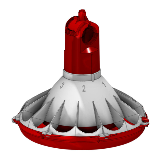
Assembling Feeder Konavi® Pullet Feeding System Assembling Feeder 1.Line up and slide the Konavi Breeder Restrictor (Item 1) into the Konavi Breeder Cone (Item 2) as shown. 2.Slide the Cone Skirt (Item 3) over the Feed Cone. 3.Line up the Molded Cutouts in the Chick Excluder (Item 4) with the raised features of the Breeder Cone and slide them together as shown. - Page 19 Konavi® Pullet Feeding System Assembling Feeder 7.Rotate the Excluder and insert the Tabs on the Excluder into the Slots in the Pan. 8.With all Excluder Tabs fully inserted into the slots in the Feeder Pan, rotate the Excluder Counter-Clockwise until the Excluder Snap Lock (Item 1) is locked in place. Item Description Snap Lock...
-
Page 20: Feeder Line Assembly And Suspension
Konavi® Pullet Feeding System Feeder Line Assembly and Suspension Installing Feeders on the Feeder Tube Installing Cone Cap 1.Line up the Feeder with the hole in the Feeder Tube (Item 1) 2.Konavi- Set a Konavi Cone Cap (Item 2) on the Feeder Tube, and Slide it past the Locking Tabs so it locks into place as shown. -
Page 21: Assembling And Suspending The Feeder Tubes
Assembling and Suspending the Feeder Tubes 1.The Feeder Tubes and Feeders may be laid out end to end in approximately the final location of the line. The belled end of each Tube should be toward the Hopper end. (See Figure 19.) 2.Connect the individual feeder tubes together by inserting the straight end of one tube as far as possible into the belled end of the next tube. -
Page 22: Installing Adjustable Hangers
Installing Adjustable Hangers •Refer to the appropriate Indexing Chart on page 25 of this manual to program the Feeder Tubes. •Find the heading for the number of tubes in your feeder line in the horizontal line at the top of the Indexing Chart. The correct hanger adjustments for each Feeder Tube are shown in the column under the heading. -
Page 23: Suspending The Feeder Line
Suspending the Feeder Line Adjustment Leveler Installation 1.Install Adjustment Levelers (Item 1) at each Adjustable Hanger. Install the S Hooks (Item 2) in the proper hole of the Hanger as shown on the previous page. 2.See Figure 21. for proper cable routing around the Adjustment Leveler. The maximum distance from the Leveler to the S Hook is 6" [152mm]. 3.Lift the Feeder line to a comfortable working height and check that the Seems in the Feeder Tube are indexed properly. - Page 24 Konavi® Pullet Feeding System Anti-Swing Clamp 1.Insert a Locking Pin (Item 1) into the slot in the Cone Cap as shown. 2.Install two Adjustable Hose Clamps (Item 2) to hold the Locking Pin in place and eliminate rotation of the Feeder on the Feeder Tube.
-
Page 25: Indexing Chart For Pullet Feeders
Konavi® Pullet Feeding System Indexing Chart for Pullet Feeders Systems using 10’ (3 m) Feeder Tube Number of Tubes MF2514A... -
Page 26: Installing The End Control And Boot Assembly
Konavi® Pullet Feeding System Installing the End Control and Boot Assembly The End Control Unit must be at least 10 feet [3 m] from the end of the building to allow birds access around the end of the feeder line. 1.Assemble the End Control Unit to the Feeder Line Control Tube using a clamp/anti-roost bracket. -
Page 27: Auger/End Control Installation
Konavi® Pullet Feeding System Auger/End Control Installation Use extreme caution when working with the auger. The auger is under tension and may spring causing personal injury. Wear protective clothing, gloves, and safety glasses when working with the auger. BE CAREFUL WHEN WORKING WITH THE AUGER! To avoid kinking the auger, be careful not to drop the rolled auger when handling. - Page 28 Konavi® Pullet Feeding System 7.Slide the Drive Tube and flat washer over the output shaft on the Power Unit, as shown in Figure 26. 8.Continue installing Auger until the Auger reaches the Control Unit end of the feeder line. 9.Turn the Drive Tube Weldment into the Auger, then attach to the output shaft of the Power Unit, as shown in Figure 26.
- Page 29 Konavi® Pullet Feeding System 11.Install the Metal Water Tight Connector (Item 1) in the Power Unit (Item 2). Cut the Flex Conduit (Item 3) to length. Slide the wires from the end control through the Flex Conduit (Item 3). Install the Flex Conduit (Item 3) in the connectors.
-
Page 30: Auger Stretch
Konavi® Pullet Feeding System Auger Stretch Use caution when working with the Auger--springing auger may cause personal injury. Proper Auger Stretch is 7" [180 mm] per 100’ [30 m]. Example: A 300’ [90 m] feeder line requires 21" [500 mm] of stretch. Measure the amount of stretch from the rear edge of the boot and cut the Auger at that point. (See Figure 29.) 1.Pull on the loose end of the Auger at the boot once or twice until it begins to stretch, then release it slowly. -
Page 31: Auger Brazing
Konavi® Pullet Feeding System Use caution when working with the Auger--springing auger may cause personal injury 6.Carefully remove the Vice Grips to allow the Auger to snap into place. 7.Install the Stub Tube (Item 1), Cap (Item 2), and Tube Clamp (Item 3) as shown. Item Description Part No... -
Page 32: Mid-Line Control
The Mid-Line Control makes it possible to operate the feeding system when birds are confined away from the End Control Unit. Chore-Time recommends placing the Mid-Line Control Feeder at least 2 pans away from the curtain or partition. (See Figure 32.) -
Page 33: Attaching The Mid-Line Control
Konavi® Pullet Feeding System Attaching the Mid-Line Control Mid-Line Control with Proximity Sensor Control The Mid-Line Control is installed on a Control Tube. The Control Tube is a special Feed Tube that has enlarged holes required for the Mid-Line Control. 1.Attach the Mid-Line Control (Item 1) to the Control Tube (Item 2) as shown in Figure 34. -
Page 34: Anti-Roost Assembly
Konavi® Pullet Feeding System Anti-Roost Assembly 1.Unroll the bulk anti-roost cable. Note: If the cable is unrolled as shown in Figure 35., taking 5 loops of the coil with one hand, then changing hands to remove 5 loops as it is unrolled, it will lie flat during installation. - Page 35 Konavi® Pullet Feeding System 9.At the control unit, after clamping the cable to the spring, cut the cable about 8" to 10" [200 to 250 mm] longer than necessary. Feed the end of the cable through the center of the spring, around the first insulator on the control unit, and clamp the cable using the cable clamp supplied with the control unit.
-
Page 36: Wiring
Konavi® Pullet Feeding System Wiring End Control with Proximity Switch Internal Wiring Power Ground Green To Motor Green White Brown Black From Sensor White Blue Proximity Sensor Wiring Diagram Bypass Switch (Not Supplied) 230 VAC Black Supply Ground Ground 60 HZ White Shown with 3259-84 Green... -
Page 37: Electronic Sensor Three Phase Wiring
Electronic Sensor Three Phase Wiring From disconnect or Control disconnect 220/380 Volts To additional 50 HZ Three Phase Feeder Lines Phase Phase Phase Neutral Set of Fuses short circuit protection (Not Supplied) Contactor Control Bypass Mid-Line Switch (Not Supplied) Control Sensor 3 PH Feeder Line Motor... -
Page 38: Power Unit Wiring
Konavi® Pullet Feeding System Power Unit Wiring 3259-144 Power (5051 Motor) Unit Wiring There are two Manufacturers of the 5703 Motor. Wiring diagrams shown for both Manufacturers. Nidec Motor Wiring Regal (GE) Marathon Motor Wiring 208/230 Volts AC 208/230 Volts AC Clockwise Rotation Clockwise Rotation 3259-153 Power Unit Wiring... -
Page 39: Troubleshooting
Konavi® Pullet Feeding System Troubleshooting ALWAYS DISCONNECT POWER TO THE SYSTEM WHEN SERVICING OR MAINTAINING THE EQUIPMENT. FAILURE TO DISCONNECT POWER MAY CAUSE INJURY OR DEATH. Service and maintenance work should be done by a qualified technician only. Problem Possible Cause Corrective Action None of the feeder lines will operate No power supplied to equipment... -
Page 40: Maintenance
Maintenance Konavi® Pullet Feeding System Maintenance Floor Feeding System Maintenance ® The KONAVI Feeders require minimum maintenance. However, a routine periodic inspection of the equipment will prevent unnecessary problems. Maintenance should be done by a qualified technician. ALWAYS DISCONNECT POWER TO THE SYSTEM WHEN SERVICING OR MAINTAINING THE EQUIPMENT. -
Page 41: Proximity Sensor Adjustment
Konavi® Pullet Feeding System Maintenance Proximity Sensor Adjustment Sensitivity Timer: The Feeder Comes with the Sensitivity Timer adjustment Screw factory set and Glued in position. (Do not Adjust). Time Delay: The Delay Time is Factory Set to 3 Minutes. See Figure 41. To adjust the Time Delay: •For less time —... -
Page 42: Feeder Line
Maintenance Konavi® Pullet Feeding System Feeder Line Keep anti-roost cables tightly stretched. This increases the effectiveness of the electro-guard anti-roost system and keep the pans from being tilted when birds push against them. Remove all feed from the feeder when there are no birds in the house and when the building is washed and disinfected. -
Page 43: Operation
Do not operate the feeding system on automatic (full demand feed) when the feed windows are open. Chore-Time recommends opening the feed windows for the first 10 to 12 days (max). The feeders will need to be operated at least 2 times a day for the first 5 days, and thereafter, 3 times a day or more as needed, while the windows are open. -
Page 44: Feeder Pan Setting
#1 Position Figure 44.Feeder Pan Setting Feed Volume Chore-Time recommends grow-out crumble feed at 45lb/ft density. If using 45lb/ft the following settings apply. (See Figure 45.) See “Manufacturer’s Recommendations: Birds per Pan” on page 7 for birds per pan recommendations. -
Page 45: Parts List
Konavi® Pullet Feeding System Parts List Parts List 150# Plastic Hopper (49268) Item Description 49268 Hopper Kit Machined Hopper Half 49270 Plastic hopper half 49028 Hopper cover 48675 Support cable assembly 2809-3 Clevis pin 2797-1 Boot adjuster bracket 2706 Suspension angles 48679 Suspension brace 48680... -
Page 46: 8798 Switch Assembly
Parts List Konavi® Pullet Feeding System 8798 Switch Assembly Item Description Part No. 6-32 x 7/8" Rd. Hd. M.S. 1921 SPDT Actuator Switch 7114 Switch Insulation 1907-5 Switch Bracket 7068 #6 x 3/8" Slot Wash. Hd. Screw 6782 6-32 Hex Nut 8757 Switch Box 7841... -
Page 47: 200# Hopper Components
Konavi® Pullet Feeding System Parts List 200# Hopper Components 7941 28358 Hopper Assembly Hopper Ass’y with cover Item Description Part No. Hopper Cover 28206 Tube Support Assembly 14367 14367 Hopper Side 2680 2680 Boot Hanger 2671 2671 Hanger Bracket Assembly 2681 2681 Adjustment Bracket... -
Page 48: 100 # Hopper Components
Parts List Konavi® Pullet Feeding System 100 # Hopper Components 28210 28220 28240** 100 lb. Hopper Cover Ass’y. 100 lb. Hopper Assembly 100 lb. Hopper & (No Cover) Cover Assembly Description Part No. Hopper Cover (w/o hole) 28211 Hopper Cover (w/ hole) 28212 Hopper Hanger 28165... -
Page 49: Hopper Mount Bracket
Konavi® Pullet Feeding System Parts List Hopper Mount Bracket Part Number 49358 - Hopper Suspension Kit Item Description Part No. Part No. Single Boot Twin Boot Clevis Pin, 5/16'' x 1'' 2797-1 2797-1 Adjustment Bracket 2706 2706 Hair Pin 2664 2664 Suspension Brace 48680... -
Page 50: Twin Boot Components Part No. 6824
Parts List Konavi® Pullet Feeding System Twin Boot Components Part No. 6824 1523-14 8/2004 Item Description Part No. Item Description Part No. Boot Weldment 3760 Anchor 38540 Tube Clamp 24063 5/16-18x7/8” Sock Hd Screw 47867 29373 Anchor and Bearing Ass’y 39372 Outlet Tube 4556... -
Page 51: Feeder Line Components
Konavi® Pullet Feeding System Parts List Feeder Line Components Item Description Part No. 1/16'' Cable 1922 3/16" Cable Clamp 1213 Spring 7551 1/16'' Cable Clamp 1826 Auger 6820-0 Tube Clamp 24063 Anti-Roost Bracket 24060 Small "S" Hook Hanger Assembly 7604 Grommet 14899 Anti-Swing Clamp Kit... -
Page 52: Konavi® Breeder Feeder Assembly (Part Number 57452)
Parts List Konavi® Pullet Feeding System ® KONAVI Breeder Feeder Assembly (Part Number 57452) Item Description Part No. Konavi Breeder Cone 56756 Konavi Breeder Restrictor 57354B Konavi Breeder Pan 57395 Konavi Breeder Cap 56753 Konavi Breeder Skirt 57355 Konavi Chick Excluder 57396 Power Winch (Part No. -
Page 53: Power Unit Assemblies
Konavi® Pullet Feeding System Parts List Power Unit Assemblies Item Description 3259-144 3259-153 Part No. Part No. Pinion Assembly 5052 5052 - - - - - - - - - - - - Pipe Plug (magnetic) 30160 30160 Driver Block 4642 4642 Motor... -
Page 54: 8798 Switch Assembly
Parts List Konavi® Pullet Feeding System 8798 Switch Assembly Item Description Part No. 6-32 x 7/8" Rd. Hd. M.S. 1921 SPDT Actuator Switch 7114 Switch Insulation 1907-5 Switch Bracket 7068 #6 x 3/8" Slot Wash. Hd. Screw 6782 6-32 Hex Nut 8757 Switch Box 7841... -
Page 55: 14485 Anti-Swing Clamp Kit
Konavi® Pullet Feeding System Parts List 14485 Anti-Swing Clamp Kit Item Part No. Description 3527 1.875 Hose Clamp 14484 Locking Pin MF2514A... -
Page 56: Konavi® Proximity Sensor End Control 57425
® KONAVI Proximity Sensor End Control 57425... - Page 57 Item Part No. Description 56084 Sensor Switch Holder 56576 Control Sensor Body 57355 Konavi Breeder Skirt 56579 Support Tube Assembly 57395 ® KONAVI Breeder Pan 48081 Center Divider 57396 Chick Excluder 48086 End Control Bottom Cover 57354B Konavi Breeder Restrictor 4416-7 10-24 Hex Screw 3527...
-
Page 58: Konavi® 57453 Proximity Sensor Mid Line Control
® KONAVI 57453 Proximity Sensor Mid Line Control 21 22... - Page 59 Item Part No. Description 57430 Konavi Breeder Cone 57355 Konavi Breeder Skirt 57396 Chick Excluder 57354B Konavi Breeder Restrictor 57395 ® KONAVI Breeder Pan 3527 1.875 Hose Clamp 56084 Switch Holder 52315 Mounting Bracket 6956 Mounting Terminal Box Cover 6777 Switch Box Gasket 42627-13 General Purpose Box...
-
Page 60: Miscellaneous Suspension Components
Parts List Konavi® Pullet Feeding System Miscellaneous Suspension Components Item Description Part No. 3/16 Cable 1213 Cable Lock 14337 Pulley with Swivel 3004 Heavy Duty Pulley Assembly 2014 Pulley 2500 3/16" Cable Clamp ATF Screw Hook 2041 Extendable drive tube 47637 Pulley Assembly 28429... - Page 61 Konavi® Pullet Feeding System Parts List This page left blank intentionally..MF2514A...
- Page 62 Revisions to this Manual Page No. Description of Change New Manual 36214 For additional parts and information, contact your nearest Chore-Time distributor or representative. Find your nearest distributor at: www.choretime.com/contacts CTB, Inc. PO Box 2000 Milford, Indiana 46542-2000 USA Phone (574) 658-4101 Fax (877) 730-8825 Email: choretime@choretime.com...
Need help?
Do you have a question about the Konavi Pullet Feeding System and is the answer not in the manual?
Questions and answers