Table of Contents
Advertisement
Quick Links
Advertisement
Table of Contents

Subscribe to Our Youtube Channel
Related Manuals for MAGSYS IGM11

Summary of Contents for MAGSYS IGM11
- Page 1 PERATING NSTRUCTIONS IGM11 NDUSTRIAL AUSSMETER...
- Page 2 Industrial Gaussmeter IGM11 Operating Instructions © 2020 MAGSYS magnet systeme GmbH All rights reserved. No part of these operating instructions may be reproduced or du- plicated without the author’s written consent. Windows is a registered trademark of Microsoft Corporation. ®...
-
Page 3: Table Of Contents
Industrial Gaussmeter IGM11 Operating Instructions Table of Contents Safety Instructions 6.3.4 Parameters of the LAN Interface Safety Instructions for the Device 6.3.5 Settings of the Digital Inputs Safety Instructions for Measuring Probes 6.3.6 Settings of the Digital Outputs Safety Symbols 6.3.7 Settings of the Function Buttons... - Page 4 Industrial Gaussmeter IGM11 Operating Instructions Table of Illustrations Display Display Basic Assembly of a Hall Probe Status Display Flux Line Characteristics of an NdFeB Induction Disk 13 Measuring Ranges Field Strength Pattern of an NdFeB Induction Disk Signal Input Plus Switched...
-
Page 5: Safety Instructions
Do not replace any parts and do not modify this product without prior and written consent by MAGSYS. Do not service this device. Return the device to MAGSYS mag- net systeme GmbH or to your local supplier for repair and maintenance to ensure that all safety features remain. -
Page 6: Safety Symbols
Gaussmeter IGM11 Operating Instructions Chapter 1 Safety Instructions Safety Symbols Safety symbols can be found on various spots of the device. Before using this connection or function, read the corresponding reference in the manual. This symbol refers to information and references in the operating instructions which the user has to follow in order to avoid injuries of persons or damage to the device, or to gain correct measuring results. -
Page 7: Brief Introduction
Industrial Gaussmeter IGM11 Operating Instructions Chapter 2 Brief Introduction Brief Introduction Measurements with the gaussmeter utilize the Hall effect as principle of measure- ment. A Hall sensor is a symmetric current-carrying semiconductor. A magnetic field running perpendicular through this element generates an asymmetry on the chip and thereby creates an output voltage which, at first approximation, is proportional to the product of magnetic field strength and forced current. -
Page 8: Measuring Unit
Gaussmeter IGM11 Operating Instructions Chapter 2 Brief Introduction Measuring Unit The gaussmeter shows measuring values in physical units of the SI-system and of the Gauss-CGS system (preferably used in North America). You can adjust the unit in the set-up menu. -
Page 9: Display
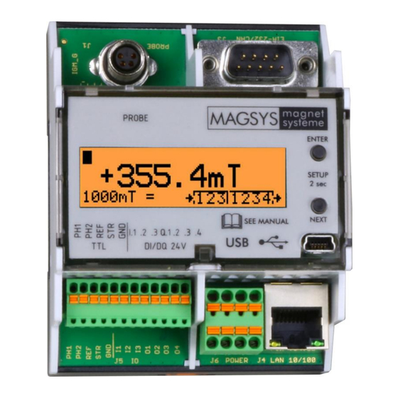
Industrial Gaussmeter IGM11 Operating Instructions Chapter 2 Brief Introduction Display The following shows a typical example of the display. Lifesign Measured value with unit Status of the digital Measuring range in- / outputs and mode Figure 1 Display Status Display Beside the currently measured value the gaussmeter displays the status information in the upper right area. -
Page 10: Function Of The Gaussmeter
Gaussmeter IGM11 Operating Instructions Chapter 3 Function of the Gaussmeter Function of the Gaussmeter The Hall Effect 3.1.1 Linear Properties of the Hall Probe The measurement is based on the deflection of charge carriers in a magnetic field inside a conductor. Thus, the basis of the measurement of the magnetic flux density is the Lorentz force. -
Page 11: Non-Linear Properties Of The Hall Probe
Industrial Gaussmeter IGM11 Operating Instructions Chapter 3 Function of the Gaussmeter This implies: Hall with Charge carriers Elementary charge of the electron (1.6022 10 Width of the path on which the electrons move Effective force of the Hall element Flux density in [Tesla] This represents the idealized Hall effect. - Page 12 Hall effect. This becomes noticeable as a flux density modulated resistance. For measuring fast magnetic impulses, the device must have sufficiently high dynamics in order to equalize this effect. The gaussmeter IGM11 is optimized for this operating mode.
-
Page 13: Measurement Details
Industrial Gaussmeter IGM11 Operating Instructions Chapter 3 Function of the Gaussmeter Measurement Details The used Hall sensors contain a very small active semiconductor area ranging at ap- prox.100 µm. The local resolution of this mesasuring method is thus rather high. Also notice that single Hall sensors measure one field component only. -
Page 14: Remanence And Hall Gaussmeter Measurement
Gaussmeter IGM11 Operating Instructions Chapter 3 Function of the Gaussmeter Figure 4 Field Strength Pattern of an NdFeB Induction Disk The diagram in figure 4 shows the measurement with a Hall probe which is moved in parallel to the surface of the magnet within a distance of 1mm to the measuring surface. -
Page 15: Accuracy Based On Positioning And Direction
Industrial Gaussmeter IGM11 Operating Instructions Chapter 3 Function of the Gaussmeter As B as well as B is measured in the unit Tesla, the magnetic field measured on the outside is often mixed up with the remanence. Please note that a magnet without back iron only shows a value clearly below the rema- nence on the surface. -
Page 16: External Static Magnetic Fields
Gaussmeter IGM11 Operating Instructions Chapter 3 Function of the Gaussmeter 3.2.4 External Static Magnetic Fields Particularly in sensitive measuring ranges, an external static magnetic field, as e.g. the Earth’s field, can already become clearly noticeable. These external magnetic fields lead to a corruption of the measuring result. -
Page 17: Control Elements And Connections
Industrial Gaussmeter IGM11 Operating Instructions Chapter 4 Control Elements and Connections Control Elements and Connections Front Panel Overview Figure 5 Front Panel Output of the measured value Display Status info ENTER-button Control of the set-up menu ... -
Page 18: Ports Overview
Gaussmeter IGM11 Operating Instructions Chapter 4 Control Elements and Connections Ports Overview Probe Port (J1) EIA-232 Port (J5) (Probe) 24V IO Ports (J6) Power Network Supply Port (J4) Figure 6 Ports Figure 7 Ports Top PROBE Interface Probe port Serial port EIA-232 for PC and... -
Page 19: Power Supply
Industrial Gaussmeter IGM11 Operating Instructions Chapter 4 Control Elements and Connections Figure 8 Ports Bottom For add-ons Interface Power Supply Do not use Port for PLC sig- Port for power sup- RJ45 port for the LAN nals ply for the device... -
Page 20: Usb Interface
Gaussmeter IGM11 Operating Instructions Chapter 4 Control Elements and Connections USB Interface The transfer of the measuring values and the entire gaussmeter control are possible via the installed standard USB interface on the front panel. The interface is specified according to the USB (Universal Serial Bus) 2.0 standard. -
Page 21: Lan Interface
Industrial Gaussmeter IGM11 Operating Instructions Chapter 4 Control Elements and Connections LAN Interface The transfer of the measured values and the entire control of the gaussmeter are possible via the standard LAN interface. The interface supports both the 10-Mbit/s-Ethernet (10BaseT) and the 100- Mbit/s-Ethernet (100BaseTX). - Page 22 Gaussmeter IGM11 Operating Instructions Chapter 4 Control Elements and Connections A prompt will not be shown. The communication is carried out with standard SCPI commands. Normal Ping requests will be answered. The MAC address (Media-Access-Control address) will be shown in hexadecimal format in the overview function of the set-up menu.
-
Page 23: Operation
Industrial Gaussmeter IGM11 Operating Instructions Chapter 5 Operation Operation Buttons The required functions are selected and triggered via two buttons. More complex parameter settings can be made via menu functions in the set-up menu. Button functions in detail: With this button you confirm the entry, select the menu item ENTER or a numerical digit. -
Page 24: Display
Gaussmeter IGM11 Operating Instructions Chapter 5 Operation Display The following shows a typical display sample. Lifesign Status Signal Error Message Measuring Value with Unit Status of the Digital Measuring Range Inputs- / Outputs and Mode Figure 12 Display Output of the actual measuring value with the correspond- ing physical unit. -
Page 25: Status Display
Industrial Gaussmeter IGM11 Operating Instructions Chapter 5 Operation Status Display Apart from the measuring value the display shows various status information. The bottom left area of the display shows the currently se- lected measuring range with the currently selected unit. -
Page 26: Measuring Ranges
Gaussmeter IGM11 Operating Instructions Chapter 5 Operation on the selected measuring unit. The ranges can only be switched manually. Normally, the measuring range is adjusted in the set-up menu. Regarding the manual switch, the measuring range is selected by multiple pressing of a button assigned in the set- up menu. -
Page 27: Measuring Unit
Industrial Gaussmeter IGM11 Operating Instructions Chapter 5 Operation Measuring Unit Select the desired measuring unit in the set-up menu. The measurement is carried out either in the unit Tesla, Gauss, kA/m or in Oersted. The display shows the selected measuring unit. The respective range limit value changes according to the selected measuring unit. -
Page 28: Ac Field Measurement
Gaussmeter IGM11 Operating Instructions Chapter 5 Operation The following shows the accuracies for DC-field measurements. Field Strength Accuracy (1σ) ≤ 1.5 T ±0.5 % > 1.5 T ±1.0 % 5.7.2 AC Field Measurement In the operating mode AC field measurement the effective value (RMS) is calculated from the determined AC field contributions. - Page 29 Industrial Gaussmeter IGM11 Operating Instructions Chapter 5 Operation Error DC Field Measurement (1σ) B ≤ 1.5 T ≤ ±0.5 % B ≥ 1.5 T ≤ ±1.0 % Frequency Response Factor (Sinusoidal Field Pattern) Frequency Factor 2 kHz 1.00 5 kHz 0.98...
-
Page 30: Peak Value Measurement
Gaussmeter IGM11 Operating Instructions Chapter 5 Operation Peak Value Measurement The device has a fast DC field peak value detection. 5.8.1 Fast Peak Value Detection The fast detection of the maximum values of DC fields is required for short magnetic impulses, as they are generated in e.g. - Page 31 Industrial Gaussmeter IGM11 Operating Instructions Chapter 5 Operation The error of the fast peak value measurement consists of the error of the DC field measurement and of a frequency factor that depends on the measuring range. Error DC Field Measurement (1σ)
-
Page 32: Probe Data
Gaussmeter IGM11 Operating Instructions Chapter 5 Operation Probe Data For a correct measurement the gaussmeter must always know the necessary probe data. A con- nected probe contains a parame- ter memory which stores the probe parameters, the serial number and the name. After changing the probe or switching on the device these data are read automatically. -
Page 33: Set-Up Menu
Industrial Gaussmeter IGM11 Operating Instructions Chapter 6 Set-up Menu Set-up Menu The following set-up options can be adapted individually in order to be able to use the device for each application in an optimal way. By pressing both buttons for ap- proximately 2 seconds, the set-up menu appears on the display. -
Page 34: Settings
Gaussmeter IGM11 Operating Instructions Chapter 6 Set-up Menu Settings 6.3.1 Overview All settings are displayed. You can scroll through the display with both buttons. This is a display example. Display of measuring value and unit Parameter of the EIA-232 interface Parameter of the LAN interface. -
Page 35: Measurement
Industrial Gaussmeter IGM11 Operating Instructions Chapter 6 Set-up Menu 6.3.2 Measurement The following options can be set individually, in order to use the device optimally for each application. Measurement Settings DC Measurement Measurement of the DC field AC Measurement Measurement of the AC field... -
Page 36: Parameters Of The Serial Interface Eia-232
Gaussmeter IGM11 Operating Instructions Chapter 6 Set-up Menu 6.3.3 Parameters of the Serial Interface EIA-232 Settings for the serial interface EIA-232 (always 8 data bits are used) Rate 1200 bit/s 1200 bps 38400 bit/s 38400 bps Number of stop bits... -
Page 37: Settings Of The Digital Inputs
Industrial Gaussmeter IGM11 Operating Instructions Chapter 6 Set-up Menu 6.3.5 Settings of the Digital Inputs Settings of digital input 1 No function This input is not used NONE The measurement is on hold Hold HOLD if the input is set... -
Page 38: Settings Of The Digital Outputs
Gaussmeter IGM11 Operating Instructions Chapter 6 Set-up Menu 6.3.6 Settings of the Digital Outputs Settings of the digital output 1 With the following function Logic function RESET IF the output will be reset. With the following function SET IF the output will be set. -
Page 39: Settings Of The Function Buttons
Industrial Gaussmeter IGM11 Operating Instructions Chapter 6 Set-up Menu 6.3.7 Settings of the Function Buttons Settings for button 1 (top / enter) Settings for button 2 (bottom / next) This button switches between Range RANGE the measuring ranges. The peak value is reset to... -
Page 40: Power Supply Connection
Gaussmeter IGM11 Operating Instructions Chapter 7 Power Supply Connection Power Supply Connection Via connector J6 the device is supplied with DC power. The operating voltage must be between 12 V and 24 V. The power consumption is 120 mA maximum at a voltage of 12 V. -
Page 41: Signal Interfaces
Industrial Gaussmeter IGM11 Operating Instructions Chapter 8 Signal Interfaces Signal Interfaces Introduction The device has three digital inputs and four digital outputs. The inputs and outputs are designed for a maximum voltage of 24 V. The inputs and outputs are insulated and potential free. The inputs resistances and the maximum allowed load are listed in the technical data. -
Page 42: Wiring Of The Inputs
Gaussmeter IGM11 Operating Instructions Chapter 8 Signal Interfaces Wiring of the Inputs Option1: The external control switches the external positive potential. Insulated DC input Used as current sinking inputs Special features. Do not connect! Figure 15 Signal Input Plus Switched This option is preferably used in European countries in order to connect a PLC control. -
Page 43: Wiring Of The Outputs
Industrial Gaussmeter IGM11 Operating Instructions Chapter 8 Signal Interfaces Wiring of the Outputs Option 1: The gaussmeter switches the positive potential provided by the customer. The load is switched against the external minus pole. Insulated DC output Used as current source outputs. -
Page 44: Serial Interfaces
Gaussmeter IGM11 Operating Instructions Chapter 9 Serial Interfaces Serial Interfaces Introduction Via the provided serial interfaces as well as via the LAN interface, all functions of the gaussmeter can be controlled by an external device (e.g. personal computer). If the gaussmeter is externally controlled, and the connected computer is supposed to carry out the data exchange, a connection is possible via this interface. -
Page 45: Connecting The Gaussmeter To An External Controller
Industrial Gaussmeter IGM11 Operating Instructions Chapter 9 Serial Interfaces Connecting the Gaussmeter to an External Controller The EIA-232 connector uses the 9-pole connector of the type DE-9 on the top right side of the device (J4). The gaussmeter can be connected to the controller or a computer which are equipped with a DTE connector (DB-25 or DE-9). -
Page 46: Connection
9.3.1 Operating Mode SCPI In this operating mode SCPI commands are evaluated and replied depending on the command type. The IGM11 will only reply on request. The command line must be terminated with the character <LF>. The reply is terminated with the characters <CR><LF>. -
Page 47: Operating Mode Short
In this operating mode simple one-character commands are evaluated and replied depending on the command type. The IGM11 will only reply on request. The com- mand line must start with <STX> and terminate with <ETX>. The reply will also be enclosed between <STX>... -
Page 48: Operating Mode Flow
Gaussmeter IGM11 Operating Instructions Chapter 9 Serial Interfaces 9.3.3 Operating Mode FLOW In this operating mode, the current measuring value is transmitted every 100ms. The measuring value is enclosed within <STX> and <ETX>. The syntax is: <STX>snnnn.<ETX> <STX>snnn.n<ETX> <STX>snn.nn<ETX> <STX>sn.nnn<ETX>... -
Page 49: Samples Of Data Transfer Eia-232
Industrial Gaussmeter IGM11 Operating Instructions Chapter 9 Serial Interfaces Samples of Data Transfer EIA-232 Mode: SCPI Master: *idnt?<LF> IGM11: MAGSYS-MAGNET-SYSTEME,IGM11,12.09.2012,E<CR><LF> Master: 2A 69 64 6E 74 3F 0A 4D 41 47 53 59 53 2D 4D 41 47 4E 45 54 2D 53 59 53... -
Page 50: Display
Gaussmeter IGM11 Operating Instructions Chapter 9 Serial Interfaces Mode: SHORT Master: <STX>?<ETX> IGM11: <STX>+355.4<ETX> Master: 02 3F 03 IGM11: 02 2B 33 35 35 2E 34 03 Master: <STX>R0<ETX> IGM11: No Reply Master: 02 52 30 03... -
Page 51: User Data
<STX> Other control characters, e.g. tabulator (0x09h), can be sent from an external con- troller in order to get a clear format. They will be ignored by the IGM11. 9.6.2 Introduction to the SCPI Language The programming language SCPI (Standard Commands for Programmable Devices) defines the way a measuring device (here the gaussmeter) can communicate with a controller. - Page 52 Gaussmeter IGM11 Operating Instructions Chapter 9 Serial Interfaces 9.6.2.3 Command Separator “;“ Several commands within the same command line string are separated by a semico- lon. By means of a semicolon the indicated path is not changed. The two following statements have the same meaning: CMD:LOW 1;:CMD:HIGH 5...
-
Page 53: Scpi Data Types
Industrial Gaussmeter IGM11 Operating Instructions Chapter 9 Serial Interfaces 9.6.3 SCPI Data Types The SCPI data language defines different data formats that are used in a program message and in a reply message. An SCPI device can normally accept commands and parameters in different formats. -
Page 54: Scpi Status Model
The status system records different device states in several register groups. The indi- vidual messages are grouped in the several registers. One bit of these registers is related to one message respectively. The IGM11 has three different event registers: measurement event register ... - Page 55 Industrial Gaussmeter IGM11 Operating Instructions Chapter 9 Serial Interfaces register, a decimal value is transmitted that corresponds to the sum of the binary place values of all bits set in this register. 9.6.4.3 Sum Register In the sum register the results of the event registers are summarized after the masking in the release register and assigned to single bits.
- Page 56 Gaussmeter IGM11 Operating Instructions Chapter 9 Serial Interfaces 9.6.4.5 Definition of the Register Bits Definition of the bits in the measurement event register Decimal Description Definition Value Overflow Range overflow during measurement Data available Measurement terminated. Data available. Definition of the bits in the error event register...
-
Page 57: Summary Of Scpi Commands
Industrial Gaussmeter IGM11 Operating Instructions Chapter 9 Serial Interfaces Summary of SCPI Commands The following conventions are used in the SCPI command syntax: Optional key words or parameters are issued in square brackets [ ] Parameters within a command character string are issued in braces { } ... -
Page 58: Peak Value Functions
Gaussmeter IGM11 Operating Instructions Chapter 9 Serial Interfaces 9.7.3 Peak Value Functions Reset the current peak values :PEAK:NULL Query the higher values of minimum and max- :PEAK:FAST:READ? imum of the fast peak value detection Query the minimum values of the fast peak... -
Page 59: Memory Functions
Industrial Gaussmeter IGM11 Operating Instructions Chapter 9 Serial Interfaces 9.7.6 Memory Functions Store the set parameters :PAR:SAVE Store the set parameters and queries the status :PAR:SAVW? Default parameter settings :PAR:DEFA 9.7.7 Serial Interfaces :SERI:COMA:BAUD[?] Bit rate of EIA-232 {1200|2400|4800|9600|14K 4|19K2|38K4}... -
Page 60: Scpi Command Reference
Gaussmeter IGM11 Operating Instructions Chapter 9 Serial Interfaces SCPI Command Reference 9.8.1 Control Commands 9.8.1.1 *RST Description: Reset Command The gaussmeter is reset to default values. The internal parameters are set to default values. A complete reset of the device is carried out. - Page 61 Industrial Gaussmeter IGM11 Operating Instructions Chapter 9 Serial Interfaces 9.8.1.4 *ESR[?] Description: Standard Event Status Enable Query Reset or query the standard event release register. The gaussmeter returns the bit pattern of the register as a decimal value. Mode: Command and query Parameter: {<Value>} within the range of 0..255...
- Page 62 Gaussmeter IGM11 Operating Instructions Chapter 9 Serial Interfaces 9.8.1.7 *OPC Description: Operation Complete Command) Set the bit "Operation complete" (bit 0) in the standard event register after the command has been completed. Mode: Command Parameter: none Response: none Value: not relevant...
- Page 63 Industrial Gaussmeter IGM11 Operating Instructions Chapter 9 Serial Interfaces 9.8.1.10 :STAT:PRESet Description: Reset the measurement event register and the standard event register. All relevant bits are set to 0. Mode: Command Parameter: none Response: none Value: not relevant *RST Example: send :STAT:PRES<LF>...
- Page 64 Gaussmeter IGM11 Operating Instructions Chapter 9 Serial Interfaces 9.8.1.13 :STAT:MEAS:ENABle[?] Description: Set or query the measurement event release register. The gaussmeter returns the bit pattern as a decimal value. Mode: Command and query Parameter: {<Value>} within the range of 0..255...
-
Page 65: Main Commands
Industrial Gaussmeter IGM11 Operating Instructions Chapter 9 Serial Interfaces 9.8.2 Main Commands 9.8.2.1 :MODE[?] Description: Set or query the DC or AC field operating mode. Mode: Command and query Parameter: {DC|AC|PEAK} DC operation mode AC operation mode PEAK DC field peak value detection... - Page 66 Gaussmeter IGM11 Operating Instructions Chapter 9 Serial Interfaces 9.8.2.3 :RANGe:SET Description: Set the measuring range of the gaussmeter. Mode: Command Parameter: {0|1|2|3} Most sensitive range Least sensitive range Response: none Value: *RST Example: send :RANG:SET 2<LF> Meaning of the parameters with different units and measuring modes.
- Page 67 Industrial Gaussmeter IGM11 Operating Instructions Chapter 9 Serial Interfaces 9.8.2.5 :READ? Description: Query the current measuring value. Identical with “MEAS?” Mode: Query Parameter: none Response: Measuring Value Value: not relevant *RST Example: send :READ?<LF> receive 2.546313e-01<CR><LF> 9.8.2.6 :MEAS? Description: Query the current measuring value. Identical with “READ?“...
-
Page 68: Peak Value Function
Gaussmeter IGM11 Operating Instructions Chapter 9 Serial Interfaces 9.8.3 Peak Value Function 9.8.3.1 :PEAK:NULL Description: Reset the current peak values. Mode: Command Parameter: none Response: none Value: not relevant *RST Example: send :PEAK:MODE NULL<LF> 9.8.3.2 :PEAK:FAST:READ? Description: Query the largest value of minimum and maximum of the fast peak value detection, according to its absolute value. - Page 69 Industrial Gaussmeter IGM11 Operating Instructions Chapter 9 Serial Interfaces 9.8.3.4 :PEAK:FAST:READ:MAX? Description: Query the maximum values of the fast peak value detection. Mode: Query Parameter: none Response: Measuring value Value: not relevant *RST Example: send :PEAK:FAST:READ?<LF> receive 9.11111e+00<CR><LF> 9.8.3.5 :PEAK:SLOW:READ?
-
Page 70: Probe Functions
Gaussmeter IGM11 Operating Instructions Chapter 9 Serial Interfaces 9.8.3.7 :PEAK:SLOW:READ:MAX? Description: Query the maximum value of the slow peak value detection. Mode: Query Parameter: none Response: Measuring value Value: not relevant *RST Example: send :PEAK:FAST:READMAX?<LF> receive 9.11111e+00<CR><LF> 9.8.4 Probe Functions 9.8.4.1 :PROB:NAME? - Page 71 Industrial Gaussmeter IGM11 Operating Instructions Chapter 9 Serial Interfaces 9.8.4.3 :PROB:TYPE? Description: Query the probe type. Mode: Query Parameter: none Response: Probe type Type Type Transversal standard Axial standard Calibration probe Transversal high field Axial high field Value: not relevant...
-
Page 72: Memory Functions
Gaussmeter IGM11 Operating Instructions Chapter 9 Serial Interfaces 9.8.5 Memory Functions 9.8.5.1 :PAR:SAVE Description: Save parameters, units and ranges in non-volatile memory. Mode: Command Parameter: none Response: none Value: not relevant *RST Example: send :PAR:SAVE<LF> 9.8.5.2 :PAR:SAVW? Description: Save parameters, units and ranges in non-volatile memory. After that, the parameter status will be returned. -
Page 73: Device Functions
Industrial Gaussmeter IGM11 Operating Instructions Chapter 9 Serial Interfaces 9.8.6 Device Functions 9.8.6.1 :SN:UNIT? Description: Query the serial number of the device. Mode: Query Parameter: none Response: Serial number Value: not relevant *RST Example: send :SN:UNIT?<LF> receive 010110078<CR><LF> 9.8.6.2 :SN:SW? Description: Query the software version of the device. - Page 74 Gaussmeter IGM11 Operating Instructions Chapter 9 Serial Interfaces 9.8.6.4 :SN:CALI? Description: Query the calibration info. Mode: Query Parameter: none Response: Calibration info Value: not relevant *RST Example: send :SN:CALI?<LF> receive CAL 01SEP12 / 01SEP14<CR><LF> 9.8.6.5 :SYST:ERR? Description: Query the error queue.
-
Page 75: Interface Functions
Industrial Gaussmeter IGM11 Operating Instructions Chapter 9 Serial Interfaces 9.8.7 Interface Functions 9.8.7.1 :SERI:COMA:BAUD[?] Description: Set or query the bit rate of the EIA-232 interface. Mode: Command or query Parameter: {1200|2400|4800|9600|14K4|19K2|38K4} Response: like parameter Value: not relevant *RST Example: send :SERI:COMA:BAUD 19K2<LF>... - Page 76 Gaussmeter IGM11 Operating Instructions Chapter 9 Serial Interfaces 9.8.7.4 :SERI:COMA:MODE[?] Description: Set or query the operating mode of the EIA-232 interface. Mode: Command or query Parameter: {SCPI|SHOR|FLOW} Response: like parameter Value: not relevant *RST Example: send :SERI:COMA:MODE SCPI<LF> send :SERI:COMA:MODE?<LF>...
- Page 77 Industrial Gaussmeter IGM11 Operating Instructions Chapter 9 Serial Interfaces 9.8.7.7 :DGIO:IN1? .. :DGIO:IN3? Description: Query the digital input state. Mode: Query Parameter: none Response: if the input is current-carrying 0|1 1: Value: not relevant *RST Example: send :DGIO:IN1?<LF> receive 1<CR><LF>...
- Page 78 Gaussmeter IGM11 Operating Instructions Chapter 9 Serial Interfaces 9.8.7.10 :DGIO:SET:IN :LOG[?] Description: Set or query the logic level of a digital input. x is for inputs 1 to 3. Mode: Command or query Parameter: 0 is for normal function (current flow sets the input)
- Page 79 Industrial Gaussmeter IGM11 Operating Instructions Chapter 9 Serial Interfaces 9.8.7.12 :DGIO:SET:OUT :LOG[?] Description: Set or query the logic level of each output. x is for outputs 1 to 4 Mode: Command or query Parameter: 0 is for normal function (current flow when this condition is fulfilled)
- Page 80 Gaussmeter IGM11 Operating Instructions Chapter 9 Serial Interfaces 9.8.7.14 :DGIO:SET:OUT :HIGH[?] Description: Set or query the upper limit value for the limit value check of each output. x represents outputs 1 to 4. Only relevant for the selected compare operation.
- Page 81 Industrial Gaussmeter IGM11 Operating Instructions Chapter 9 Serial Interfaces 9.8.7.16 :KEYS:BOT:FUNC[?] Description: Set or query the function of the lower key (NEXT) on the front panel. Mode: Command or query Parameter: NO|RANG|PKNL|NULL Parameter Function No function assigned to this key...
-
Page 82: Table Of Error Messages
Gaussmeter IGM11 Operating Instructions Chapter 10 Table of Error Messages Table of Error Messages Errors inside the device are stored in the error queue. It can be read out via an SCPI command or via the set-up menu. The messages have the following meanings:... - Page 83 Industrial Gaussmeter IGM11 Operating Instructions Chapter 10 Table of Error Messages EIA232 buffer overflow Buffer overflow on the serial interface EIA- 232. If necessary, reduce the bit rate. Check the command. Undefined error Undefined error. Forward the error number to the service.
-
Page 84: Unit Conversion Table
Gaussmeter IGM11 Operating Instructions Chapter 11 Unit Conversion Table Unit Conversion Table This table shows the relationship between the displayed measuring values. Dis- Dimension Unit Conversion play Mag. flux Tesla density B Flux density Gauss ... -
Page 85: Technical Data
Industrial Gaussmeter IGM11 Operating Instructions Chapter 12 Technical Data Technical Data General Power Supply Supply voltage feed 11.4 V to 26.4 V DC; Current consumption (nominal): 120 mA with 12 V; 85 mA with 24 V (with display backlight) 70 mA with 12 V; 50 mA with 24 V (without display backlight) - Page 86 Gaussmeter IGM11 Operating Instructions Chapter 12 Technical Data Ethernet Norm IEEE 802.3 (TCP/IP) Connector 8-pole RJ45 socket Bit rate 10 Mbits/s and 100 Mbits/s IP address parametrizable Subnet parametrizable Function Data output Data protocol RFC 854 (Telnet) Signal Interfaces Digital Inputs...
- Page 87 Industrial Gaussmeter IGM11 Operating Instructions Chapter 12 Technical Data Measuring Properties Meas. method Continuous recording of the magnetic field; conversion via 16-bit A/D-converter; Evaluation via 16 bit microprocessor system. Display refresh time 100 ms; Display resolution Depending on range 3 to 4-digit Frequency range DC / AC 0 Hz ..
- Page 88 Gaussmeter IGM11 Operating Instructions Chapter 12 Technical Data Units Tesla Gauss Oersted Ampere/meter Meas. ranges 4.5 T 45 kG 45 kOe 3500 kA/m [10 T] [100 kG] [100 kOe] [8000 kA/m] (1 mT) (10 G) (10 Oe) (1 kA/m) DC-field measurement...
-
Page 89: Declaration Of Conformity
Date / Datum M. Kopka Dipl.Ing. CEO For further information, please contact your local MAGSYS magnet systeme sales office, agent or distributor, or MAGSYS magnet sys- teme GmbH, Rohwedderstr. 7, 44369 Dortmund, Germany. WWW.MAGSYS.DE Für weitere Informationen kontaktieren Sie bitte Ihr örtliches MAGSYS magnet systeme Vertriebsbüro, Handelsvertreter oder Händler oder direkt MAGSYS magnet systeme GmbH, Rohwedderstr. -
Page 90: Warranty And Copyright
The above-mentioned measures are the only and exclusive striving to fix any mistake as fast as possible. measures on the side of the buyer. MAGSYS magnet systeme GmbH is not liable for direct, indirect, particular damages or Verification of Suitability... -
Page 91: Index
Industrial Gaussmeter IGM11 Operating Instructions Chapter 15 Index Index PARY ............75 STOP ............75 :STAT *CLS ..............60 MEAS *ESE ..............60 ENAB ............64 *ESR ..............61 EVEN ............64 *IDN..............61 PRES .............. 63 *OPC ............61, 62 QUES *RTS .............. - Page 92 Gaussmeter IGM11 Operating Instructions Chapter 15 Index CAL .............. 71 NAME ............70 Fast Peak Value Detection ........30 SN ..............70 Field strength ............84 TYPE ............. 71 FLOW ..............48 Probe Connection ..........19 Flux density ............84 Probe Data ............
Need help?
Do you have a question about the IGM11 and is the answer not in the manual?
Questions and answers