Seagate RealStor 5005 Series Hardware Installation
Hide thumbs
Also See for RealStor 5005 Series:
- Getting started (2 pages) ,
- Hardware installation and maintenance manual (150 pages)
Table of Contents
Advertisement
Quick Links
RealStor 5005/4005 Series
Hardware Installation and
Maintenance Guide
Abstract
This document describes initial hardware setup for Seagate RealStor 5005/4005 Series enclosures. It also describes
removal and installation of customer-replaceable units for these enclosures. The document is intended for use by
storage system administrators familiar with servers and computer networks, network administration, storage system
administration and configurations, storage area network management, and relevant protocols.
Firmware Version: G250
P/N 83-00007051-10-01
Revision A
March 2017
Advertisement
Table of Contents
Troubleshooting

Subscribe to Our Youtube Channel
Related Manuals for Seagate RealStor 5005 Series


Summary of Contents for Seagate RealStor 5005 Series
- Page 1 Maintenance Guide Abstract This document describes initial hardware setup for Seagate RealStor 5005/4005 Series enclosures. It also describes removal and installation of customer-replaceable units for these enclosures. The document is intended for use by storage system administrators familiar with servers and computer networks, network administration, storage system administration and configurations, storage area network management, and relevant protocols.
- Page 2 Seagate Technology LLC or its affiliates. Any use, derivation, dissemination, reproduction, or any attempt to modify, reproduce, distribute, disclose copyrighted material of Seagate Technology LLC, for any reason, in any manner, medium, or form, in whole or in part, if not...
-
Page 3: Table Of Contents
Contents About this guide ..............10 Introduction . - Page 4 3 Installation..............35 Installation checklist .
- Page 5 580W PCM LEDs..................58 Ops panel LEDs .
- Page 6 Replacing a storage enclosure chassis ............... . . 92 Before you begin .
- Page 7 Figures 1 2U12 enclosure system – dimetric front orientation ............17 2 2U12 enclosure system –...
- Page 8 49 Installing a LFF drive carrier module (2 of 2) ..............83 50 Activating the anti-tamper lock .
- Page 9 Tables 1 Related documents..................12 2 Document conventions .
-
Page 10: About This Guide
This guide provides information about initial hardware setup, and removal and installation of customer-replaceable units (CRUs) for the Seagate RealStor™ 5005/4005 Series controller enclosures, which can be used with J1212/J1224 expansion enclosures. In controller enclosures, controller modules can be purchased with either of two types of host interface: SAS or FC/iSCSI. -
Page 11: Cnc Ports Used For Host Connection
CNC ports used for host connection Certain models use Converged Network Controller (CNC) technology, allowing you to select the desired host interface protocol from the available Fibre Channel (FC) or Internet SCSI (iSCSI) host interface protocols supported by the system. You can use the CLI to set all controller module CNC ports to use one of these host interface protocols: •... -
Page 12: Related Documentation
Related documentation Table 1 Related documents For information about Enhancements, known issues, and late-breaking Release Notes information not included in product documentation Regulatory compliance and safety and disposal RealStor Product Regulatory Compliance and Safety* information Overview of hardware installation RealStor Getting Started* Obtaining and installing a license to use licensed RealStor Obtaining and Installing a License features... - Page 13 IMPORTANT: Provides clarifying information or specific instructions. NOTE: Provides additional information. TIP: Provides helpful hints and shortcuts. Document conventions and symbols...
-
Page 14: Safety Guidelines
Safety guidelines Safe handling CAUTION: Use this equipment in a manner specified by the manufacturer: failure to do this may cancel the protection provided by the equipment. • Permanently unplug the enclosure before you move it or if you think that it has become damaged in any way. •... -
Page 15: Rack System Safety Precautions
IMPORTANT: The enclosure must be grounded before applying power. • The plug on the power supply cord is used as the main disconnect device. Ensure that the socket outlets are located near the equipment and are easily accessible. • 2U enclosures are intended to operate with two PCMs. •... -
Page 16: System Overview
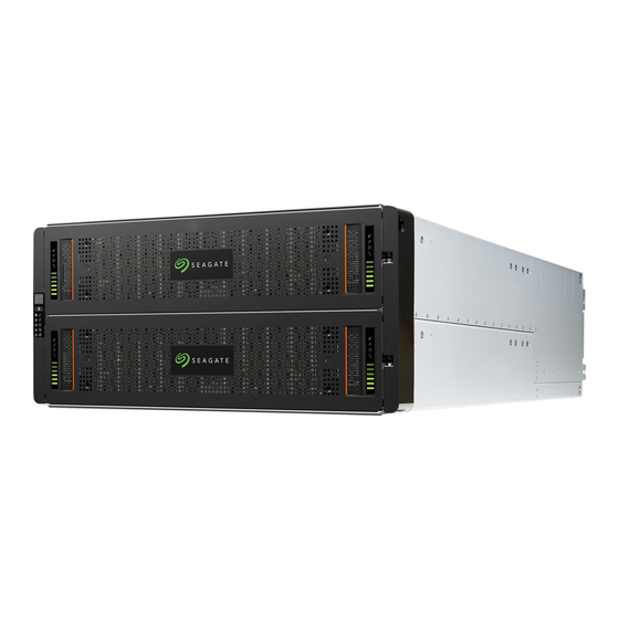
System overview Enclosure configurations The storage system supports two controller enclosure configurations. • 2U (rack space) controller enclosure – see Figure 1 (page 17) Figure 2 (page 17): holds up to 12 low profile (1-inch high) 3.5" form factor disk drive modules in a horizontal orientation. •... -
Page 17: 2U12 Enclosure System - Dimetric Front Orientation
NOTE: Please refer to “Enclosure variants” (page 19) for details about various enclosure options. Figure 1 2U12 enclosure system – dimetric front orientation Figure 2 2U12 enclosure system – dimetric rear orientation The 2U12 controller enclosure above is equipped with dual-controllers (4-port FC/iSCSI model shown). Supercapacitor pack... -
Page 18: 2U24 Enclosure System - Dimetric Front Orientation
NOTE: Please refer to “Enclosure variants” (page 19) for details about various enclosure options. Figure 3 2U24 enclosure system – dimetric front orientation Figure 4 2U24 enclosure system – dimetric rear orientation The 2U24 controller enclosure above is equipped with dual-controllers (4-port SAS model shown). System overview... -
Page 19: Enclosure Variants
Enclosure variants The RealStor 2U chassis can be configured as a controller enclosure (5005, 4005) or an expansion enclosure (J1212/J1224) as shown in Table 3 Table 2U12 12 x LFF (Large Form Factor) disk drives Table 3 2U12 enclosure variants Product Configuration PCMs... -
Page 20: Enclosure Front Panel
Enclosure front panel Integers on disks indicate drive slot numbering sequence. Figure 5 2U12 enclosure system – front panel components 12 13 17 18 19 20 21 22 23 Figure 6 2U24 enclosure system – front panel components Enclosure rear panel Numeric designators on PCMs and alphabetic designators on IOMs indicate slot sequencing for modules used in 2U enclosures. -
Page 21: Expansion Module Detail (J1212/J1224)
Rear panel components Controller modules The top slot for holding IOMs is A and the bottom slot is B. The face plate details of the IOMs show the modules aligned for use in A. In this orientation, the IOM latch appears at the bottom of the module. It is shown in closed/locked position. The diagrams below identify ports. -
Page 22: Enclosure Chassis
IMPORTANT: RBOD/EBOD configurations: • When the expansion module shown above (Figure 12) is used with 5005/4005 Series controller modules for adding storage, its middle HD mini-SAS expansion port (“B”) is disabled by the firmware. See also Figure 29 (page 40) •... -
Page 23: Operator's (Ops) Panel
• At the rear, the chassis assembly can hold a maximum of two PCMs and two SBB-compliant IOMs. IMPORTANT: The RealStor enclosures support SBB dual-controller configuration only. Single-controller support is provided only when a controller fails over to its partner controller. For RBODs and EBODs, an IOM must be installed in each IOM slot to ensure sufficient air flow through the enclosure during operation. -
Page 24: System Power On/Standby Led (Green/Amber)
the panel’s functions. An integral part of the enclosure chassis, the Ops panel is not replaceable on site. The Ops panel provides the functions shown in the illustration below and listed in the table. See also “Ops panel LEDs” (page 58). -
Page 25: Power Cooling Module
Power cooling module AC-DC power is provided by up to two auto-ranging power cooling modules (PCMs) with integrated axial cooling fans. The IOMs control fan speed. Also see “System airflow” (page 26) for optimal cooling within the enclosure(s). 580W PCM The 580W PCM voltage operating range is nominally 100V–240V AC, and operates at 50–60 Hz input frequency. -
Page 26: System Airflow
System airflow The system must be operated with low pressure rear exhaust installation. Back pressure created by rack doors and obstacles is not to exceed 5 pascals (0.5mm water gauge). The cooling system provides sufficient capacity to ensure that maximum temperatures are not exceeded. IMPORTANT: The environment in which the enclosure operates must be dust-free to ensure adequate airflow. -
Page 27: Leds: 5005/4005 Series Fc/Iscsi Controller Modules (Fc And 10Gbe Sfps)
= iSCSI (2) = FC (1) LED Description Definition Host 4/8/16Gb FC Off — No link detected. Link Status/ Green — The port is connected and the link is up. Link Activity Blinking green — The link has I/O activity. Host 10GbE iSCSI Off —... -
Page 28: Leds: 5005/4005 Series Iscsi Controller Module (1Gb Rj-45 Sfps)
= FC (1) = iSCSI (2) LED Description Definition Not used in example The FC SFP is not shown in this example. Host 1Gb iSCSI Off — No link detected. Link Status/ Green — The port is connected and the link is up. Link Activity Blinking green —... -
Page 29: Leds: 5005/4005 Series Sas Controller Module (Hd Mini-Sas)
1 = HD mini-SAS host ports LED Description Definition Host 12Gb SAS Green — The port is connected and the link is up. Link Status/ Amber — Partial link exists (one or more lanes down). Link Activity Blinking green or amber — Host link activity is detected. Green —... -
Page 30: Controller Failure When A Single-Controller Is Operational
When a controller is shut down or otherwise rendered inactive—its Link Status LED remains illuminated— falsely indicating that the controller can communicate with the host. Though a link exists between the host and the chip on the controller, the controller is not communicating with the chip. To reset the LED, the controller must be power-cycled. Cache Status LED details Power on/off behavior The storage enclosure's unified CPLD provides integrated Power Reset Management (PRM) functions. -
Page 31: 12Gb/S Expansion Module Leds
If the controller has failed or does not start, is the Cache Status LED on/blinking? Answer Action No, the Cache LED status is off, and the controller If the problem persists, replace the controller module. does not boot. No, the Cache Status LED is off, and the controller The system has flushed data to disks. -
Page 32: Drive Carrier Module
The following table provides companion data for the figure above relative to LED states for A/B/C SAS port expansion. Table 7 LEDs: J1212/J1224 expansion activity states Condition Activity (Green) Fault (Amber) No cable present Cable present: all links up/no activity Cable present: all links up/with aggregate port activity Blinking Critical fault: Any fault causing operation of the cable to cease or fail to start (e.g.,... - Page 33 NOTE: Dimetric pictorial views of supported drive carriers are provided in the following illustrations. Modules are shown oriented for insertion into disk drive slots located on the enclosure front panel. 3.5" SAS drive Figure 23 Dual path LFF 3.5" disk drive carrier modules Figure 24 Dual path SFF 2.5"...
-
Page 34: Drive Status Indicators
Drive status indicators Green and amber LEDs on the front of each drive carrier module indicate disk drive status. The SEP controls these LEDs. “Disk drive carrier module LEDs” (page 59) describes the LED states. Dummy drive carrier modules Dummy drive carrier modules, also known as drive blanks, are provided in 3.5" (2U12) and 2.5" (2U24) form factors. They must be installed in empty disk drive slots to create a balanced air flow. -
Page 35: Installation
Installation Installation checklist This chapter shows how to plan for and successfully install your enclosure system into an industry standard 19-inch rack cabinet. CAUTION: To install the system, use only the power cords supplied, or power cables that match the specification quoted in “AC power cords”... -
Page 36: Preparing For Installation
• 2U controller enclosure rear panel: see Figure 7 (page 20) • 2U expansion enclosure rear panel: see Figure 9 (page 20) (product option) IMPORTANT: Installation work should be performed by qualified service personnel. Table 9 Storage system configuration Module type Location Description Drive carrier... -
Page 37: Unpacking The Enclosure
Unpacking the enclosure 1. Examine the packaging for crushes, cuts, water damage, or any other evidence of mishandling during transit. If you suspect that damage has happened, photograph the package before opening, for possible future reference. Retain original packaging materials for use with returns. 2. -
Page 38: Rackmount Rail Kit
• The rack should cause a maximum back pressure of 5 pascals (0.5 mm water gauge). • Before you begin, ensure that you have adequate clearance in front of the rack for installing the rails. Rackmount rail kit Various sets of rack mounting rails are available for use in 19-inch rack cabinets. These rails have been designed and tested for the maximum enclosure weight, and to make sure that multiple enclosures may be installed without loss of space within the rack. -
Page 39: Fde Considerations
Cable requirements for expansion enclosures When adding storage, use only Seagate RealStor or OEM-qualified cables, and observe the following guidelines: • When installing SAS cables to expansion modules, use only supported HD mini-SAS x4 cables. - Page 40 NOTE: For clarity, the schematic diagrams show only relevant details such as IOM face plate outlines and expansion ports. For detailed illustrations see “Enclosure rear panel” (page 20). Controller A Controller A Controller B Controller B Add enclosures up to maximum (10) Add enclosures up to maximum (10) Reverse cabling Straight-through cabling...
-
Page 41: Power Cord Connection
Power cord connection Connect a power cord from each PCM on the enclosure rear panel to the PDU (power distribution unit) as shown in the illustration below (4-port SAS model is shown in the example). Controller Enclosure Power Distribution Units (AC UPS shown) Figure 30 Typical AC power cord connection from PDU to PCM IMPORTANT: When more than one PCM is fitted, all power cords must be connected to at least two separate and independent power supplies to ensure redundancy. -
Page 42: Cabling Considerations
Use native Microsoft MPIO DSM support with Windows Server 2008, Windows Server 2012, and Windows Server 2016. Use either the Server Manager or the mpclaim CLI tool to perform the installation. See the following web sites for information about using native Microsoft MPIO DSM: https://support.microsoft.com https://technet.microsoft.com (search the site for “multipath I/O overview”) - Page 43 IMPORTANT: Use the CLI set host-port-mode command to set the host interface protocol for CNC ports using qualified SFP options. 5005/4005 Series models ship with CNC ports configured for FC. When connecting CNC ports to iSCSI hosts, you must use the CLI (not the SMC) to specify which ports will use iSCSI. It is best to do this before inserting the iSCSI SFPs into the CNC ports (see “Change the CNC port mode”...
-
Page 44: Hd Mini-Sas
TIP: See the “Configuring CHAP” topic in the Storage Management Guide. TIP: Use the SMC Configuration Wizard to set iSCSI port options. Within the Storage Management Guide, see “Configuring host ports.” Use the CLI set host-parameters command to set iSCSI port options, and use the CLI show ports command to view information about host ports. -
Page 45: Hd Mini-Sas Host Connection
lengths specified for 10GbE iSCSI above. In addition to providing host connection, these cables are used for connecting two storage systems via a switch, to facilitate use of the optional replication feature. HD mini-SAS host connection To connect controller modules supporting HD mini-SAS host interface ports to a server HBA, using the controller’s SFF-8644 dual HD mini-SAS host ports, select a qualified HD mini-SAS cable option. -
Page 46: Connecting Hosts: 5005/4005 Series Direct Attach - Four Servers/ One Hba Per Server/ Dual Path
Server 1 Server 2 Controller enclosure Server 4 Server 3 Figure 33 Connecting hosts: 5005/4005 Series direct attach – four servers/ one HBA per server/ dual path Switch attach A switch attach solution—or SAN—places a switch between the servers and the controller enclosures within the storage system. -
Page 47: Connecting A Management Host On The Network
Server 2 Server 1 Server 3 Server 4 Controller enclosure Figure 35 Connecting hosts: 5005/4005 Series switch attach – four servers/ multiple switches/ SAN fabric Connecting a management host on the network The management host directly manages storage systems out-of-band over an Ethernet network. 1. -
Page 48: Obtaining Ip Values
Obtaining IP values You can configure addressing parameters for each controller module’s network port. You can set static IP values or use DHCP. DHCP is enabled by default on 5005/4005 Series systems. TIP: See the “Configuring network ports” topic in the Storage Management Guide. Setting network port IP addresses using DHCP In DHCP mode, network port IP address, subnet mask, and gateway values are obtained from a DHCP server if one is available. -
Page 49: Terminal Emulator Display Settings
Within the illustration below, the IOM is aligned for use in the bottom (0B) controller module slot. Figure 36 Connecting a USB cable to the CLI port 3. Enable the CLI port for subsequent communication: Linux customers should enter the command syntax provided in “Setting parameters for the device driver”... - Page 50 b. Enter the default password !manage. If the default user or password—or both—have been changed for security reasons, enter the secure login credentials instead of the defaults shown above. 7. At the prompt, enter the following CLI command to set the values you obtained in step 1 for each network port, first for controller A, and then for controller B:...
-
Page 51: Change The Cnc Port Mode
If communication with the CLI is disrupted when using an out-of-band cable connection, communication can sometimes be restored by disconnecting and reattaching the mini-USB CLI cable as described in step 2 Figure 36 (page 49). Change the CNC port mode This subsection applies to 5005/4005 Series FC/iSCSI models only. -
Page 52: Cabling For Replication
• Ensure that all ports assigned for replication are able to communicate appropriately with the replication system (see the CLI Reference Guide for more information): For virtual replication, use the CLI query peer-connection command. • Allow two ports to perform replication. This permits the system to balance the load across those ports as I/O demands rise and fall. -
Page 53: Connecting Two 5005/4005 Series Storage Systems For Replication: Multiple Servers/Switches/One Location
Figure 38 shows I/O and replication occurring on different networks. For optimal protection, use two switches. Connect two (5005/4005) ports from each controller module to the first switch to accommodate I/O traffic, and connect two (5005/4005) ports from each controller module to the second switch to facilitate replication. Using two switches in tandem avoids the potential single point of failure inherent to using a single switch;... -
Page 54: Operation
Operation Before you begin Before powering on the enclosure system, make sure that all modules are firmly seated in their correct slots. Verify that you have successfully completed the sequential “Installation Checklist” instructions in Table 8 (page 35). Once you have completed steps 1 through 9, you can access the management interfaces using your web-browser to complete the system setup. -
Page 55: Operator's (Ops) Panel Leds
Operator’s (Ops) panel LEDs Figure 40 (page 55) provides an illustration showing the Ops panel layout and a table describing LED behavior. See Table 13 (page 58) for details pertaining to fault indications. System Power Module Fault Identity LED display Ops panel LEDs Behavior System Power... -
Page 56: Configuring And Provisioning The Storage System
both—have been changed for security reasons, enter the secure login credentials instead of the defaults shown above. This brief sign-in discussion assumes proper web browser setup. IMPORTANT: For detailed information about accessing and using the SMC, see the “Getting Started” section in the web-posted Storage Management Guide. -
Page 57: Troubleshooting And Problem Solving
Troubleshooting and problem solving These procedures are intended to be used only during initial configuration, for the purpose of verifying that hardware setup is successful. They are not intended to be used as troubleshooting procedures for configured systems using production data and I/O. NOTE: For further troubleshooting help, after setup and when data is present, contact customer support at the Customer Resource Center web site: https://crc.dothill.com. -
Page 58: 580W Pcm Leds
580W PCM LEDs Under normal conditions, the PCM OK LEDs will be a constant green. See also Figure 17 (page 25). When a fault occurs, the colors of the LEDs will display as shown in the following table. Table 12 PCM LED states PCM OK Fan Fail AC Fail... -
Page 59: Disk Drive Carrier Module Leds
• If the above actions do not resolve the fault, contact Seagate for assistance. Disk drive carrier module LEDs Disk drive status is monitored by a green LED and an amber LED mounted on the front of each drive carrier module, as... -
Page 60: Iom Leds
IOM LEDs IOM LEDs pertain to controller modules and expansion modules, respectively. Expansion enclosures are supported for optionally adding storage. See also “12Gb/s controller module LEDs” (page 26). Controller module LEDs Table 14 Controller module LED states CRU OK CRU Fault External host port (Green) (Amber) -
Page 61: Troubleshooting
Troubleshooting The following sections describe common problems that can occur with your enclosure system, and some possible solutions. For all of the problems listed in Table 16, the module fault LED on the Ops panel will light amber to indicate a fault. -
Page 62: Thermal Monitoring And Control
Fault isolation methodology Seagate 5005/4005 Series storage systems provide many ways to isolate faults. This section presents the basic methodology used to locate faults within a storage system, and to identify the pertinent CRUs affected. Troubleshooting and problem solving... -
Page 63: Basic Steps
As noted in “Accessing the SMC” (page 55), use the Storage Management Console to configure and provision the system upon completing the hardware installation. As part of this process, configure and enable event notification so the system will notify you when a problem occurs that is at or above the configured severity (see the Configuring event notification topic within the Storage Management Guide). -
Page 64: Performing Basic Steps
monitoring/management is often done at a management console using storage management interfaces, rather than relying on line-of-sight to LEDs of racked hardware components. Performing basic steps You can use any of the available options described above in performing the basic steps comprising the fault isolation methodology. -
Page 65: If The Enclosure Does Not Initialize
If the enclosure does not initialize It may take up to two minutes for all enclosures to initialize. If an enclosure does not initialize: • Perform a rescan • Power cycle the system • Make sure the power cord is properly connected, and check the power source to which it is connected •... - Page 66 IMPORTANT: Do not perform more than one step at a time. Changing more than one variable at a time can complicate the troubleshooting process. Host-side connection troubleshooting featuring CNC ports The procedure below applies to controller enclosures employing small form factor pluggable (SFP) transceiver connectors in 4/8/16Gb/s FC, 10GbE iSCSI, or 1Gb/s iSCSI host interface ports.
- Page 67 Is the host link status/link activity LED on? Yes – You have isolated the fault to the HBA. Replace the HBA. No – It is likely that the controller module needs to be replaced. 12. Move the cable and SFP back to its original port. Is the host link status/link activity LED on? No –...
-
Page 68: Isolating A Controller Module Expansion Port Connection Fault
Isolating a controller module expansion port connection fault During normal operation, when a controller module’s expansion port is connected to a drive enclosure, the expansion port status LED is green. If the connected port’s expansion port LED is off, the link is down. Use the following procedure to isolate the fault. -
Page 69: Isolating Replication Faults
Isolating replication faults Replication setup and verification After storage systems are cabled for replication, you can use the SMC to prepare for using the replication feature. Alternatively, you can use telnet to access the IP address of the controller module and access the replication feature using the CLI. -
Page 70: Diagnostics For Replication Setup: Using The Replication Feature
Diagnostic steps for replication setup The tables in this subsection show menu navigation for virtual replication using the SMC. Can you successfully use the replication feature? Answer Possible reasons Action System functioning properly. No action required. The replication feature is not licensed Verify licensing of the optional feature per system: on each controller enclosure used for •... -
Page 71: Diagnostics For Replication Setup: Viewing Information About Remote Links
Can you view information about remote links? Answer Possible reasons Action System functioning properly. No action required. Communication link is down. • Verify controller enclosure cabling. Also see Table 17 (page 70). • Review the event logs for indicators of a specific fault in a host or replication data path component. -
Page 72: Continuous Operation During Replacement
Answer Possible reasons Action Nonexistent replication set. • Determine existence of primary or secondary volumes. • If a replication set has not been successfully created, use the Replications topic: select Action > Create Replication Set to create one. • Review event logs (in the footer, click the events panel and select Show Event List) for indicators of a specific fault in a replication data path component. -
Page 73: Firmware Updates
NOTE: The following tables share the table endnotes located beneath them. See Figure 42 (page 76) for pictorial views of IOM CRUs used in the different Seagate RealStor enclosures. Table 22 5005 Series enclosure models RealStor 5005 Series: 4-port controller enclosure matrix 2.5"... -
Page 74: Crus Addressing 2U 12-Drive Chassis
CRUs addressing 2U 12-drive chassis Table 24 5005/4005 Series product components for 2U 12-drive chassis Item Enclosure component description Disk drive (LFF) a) 3.5" disk drive module (disks of differing type/speed and storage capacity: SAS, SSD) b) Dummy drive carrier module (blank to maintain optimum air flow within enclosure) Ear components (not customer replaceable) a) Left ear assembly b) Right ear assembly... -
Page 75: Crus Addressing 2U 24-Drive Chassis
CRUs addressing 2U 24-drive chassis Table 25 5005/4005 Series product components for 2U 24-drive chassis Item Enclosure component description Disk drive (SFF) a) 2.5" disk drive module (disks of differing type/speed and storage capacity: SAS, SSD) b) Dummy drive carrier module (blank to maintain optimum air flow within enclosure) Ear components (not customer replaceable) a) Left ear assembly b) Right ear assembly... - Page 76 4-port FC/iSCSI controller module 4-port SAS controller module С 3-port expansion module Figure 42 SBB IOMs used in 5005/4005 Series storage enclosures Troubleshooting and problem solving...
-
Page 77: Module Removal And Replacement
Module removal and replacement Overview This chapter provides procedures for replacing CRUs (customer-replaceable units), including precautions, removal instructions, installation instructions, and verification of successful installation. Each procedure addresses a specific task. Certain procedures refer to related documentation. See “Related documentation” (page 12) for a list of these documents and where to find them online. -
Page 78: Replacing A Power Cooling Module
Replacing a power cooling module This section provides procedures for replacing a failed power cooling module (PCM). Illustrations in PCM replacement procedures show rear panel views of the enclosure, with the PCM properly oriented for insertion into the rear panel of the enclosure. - Page 79 7. Grasp the latch and the side of the PCM handle between thumb and fore-finger, squeeze together and open the handle to cam the PCM out of the enclosure as shown in Figure Figure 43 Removing a PCM (1 of 2) 8.
-
Page 80: Installing A Pcm
Installing a PCM Refer to Figure 43 (page 79) Figure 44 (page 79) when performing this procedure, but ignore the directional arrows—since you will insert the module into the slot—rather than extracting it. IMPORTANT: Handle the PCM carefully, and avoid damaging the connector pins. Do not install the PCM if any pins appear to be bent. -
Page 81: Removing A Lff Drive Carrier Module
Removing a LFF drive carrier module 1. Press the latch in the carrier handle towards the handle hinge to release the carrier handle as shown below. Figure 45 Removing a LFF disk drive module (1 of 2) 2. Gently move the drive carrier module approximately 25 mm (1-inch), then wait 30 seconds. Figure 46 Removing a LFF disk drive module (2 of 2) 3. -
Page 82: Installing A Lff Drive Carrier Module
Installing a LFF drive carrier module CAUTION: A drive carrier module cannot be installed if its anti-tamper lock is activated outside the enclosure. See step 1 of the procedure described on page 1. Release the drive carrier handle by depressing the latch in the handle. Figure 47 LFF drive carrier module in open position 2. -
Page 83: Using The Anti-Tamper Locks
4. Cam the drive carrier home. The camming foot on the carrier will engage into a slot in the enclosure. Continue to push firmly until the handle fully engages. You should hear a click as the latch handle engages and holds the handle closed. Figure 49 Installing a LFF drive carrier module (2 of 2) 5. -
Page 84: Removing A Sff Drive Carrier Module
Removing a SFF drive carrier module The removal/replacement procedure for SFF drive carrier modules is basically the same as for LFF models, except that the SFF carriers are mounted vertically. 1. Press the latch in the carrier handle downward to release the carrier handle so that it can revolve outward as shown below. Figure 51 Removing a SFF disk drive module (1 of 2) 2. -
Page 85: Installing A Sff Drive Carrier Module
Installing a SFF drive carrier module 1. If the anti-tamper lock is engaged, unlock it per the instructions provided in “Using the anti-tamper locks” (page 83). 2. Release the carrier handle by pressing the latch in the handle downwards, and opening the hinged handle as shown Figure 53 (page 85). -
Page 86: Replacing A Dummy Drive Carrier
4. Cam the carrier home. The camming lever on the carrier will engage into the a slot in the enclosure. Continue to push firmly until the handle fully engages. You should hear a click as the latch handle engages and holds the handle closed. Figure 55 Installing a SFF drive carrier module (2 of 2) 5. -
Page 87: Before You Begin
TIP: The illustrations show IOM module replacement within the top slot (A) as you view the enclosure rear panel. To replace an IOM in the bottom slot (B), you would first rotate the module 180º about its longitudinal axis, so that it properly aligns with its connectors on the back of the midplane. -
Page 88: Stopping I/O
• As an alternative to using the SMC, you can run the CLI show system command to view the health of the system and its components. If any component has a problem, the system health will be Degraded, Fault, or Unknown. If you discover a problem component, follow the actions in its Health Recommendations field to resolve the problem. -
Page 89: Removing An Iom
6. Select Yes to continue; otherwise, select No. If you selected Yes, a message describes shutdown activity. NOTE: If an iSCSI port is connected to a Microsoft Windows host, the following event is recorded in the Windows event log: Initiator failed to connect to the target. NOTE: See the Storage Management Guide for additional information. -
Page 90: Installing An Iom
5. Swing the latch handle open as shown in detail No.2 within Figure 4-port FC/iSCSI controller module shown Figure 56 Removing an IOM 6. Grip the latch handle and ease the IOM forward from the slot as shown in detail No.2 within Figure NOTE: The illustration above shows a 4-port controller module of model type FC/iSCSI. -
Page 91: Verifying Component Operation
NOTE: When performing the following procedure, refer to Figure 56 (page 90) while ignoring the directional arrow. For installation, the IOM will travel in the opposite direction relative to the arrow shown. 1. Examine the IOM for damage, and closely inspect the interface connector. Do not install if the pins are bent. 2. -
Page 92: Replacing A Storage Enclosure Chassis
Replacing a storage enclosure chassis The controller enclosure or expansion enclosure chassis replacement procedure replaces a damaged chassis CRU. The procedure includes removing all CRU modules from a damaged chassis and installing them into a replacement chassis. IMPORTANT: RealStor 5005/4005 Series enclosures using 2U12 or 2U24 chassis are described in “5005 Series enclosure models”... -
Page 93: Removing A Damaged Storage Enclosure Chassis From The Rack
Table 26 Replacing a storage enclosure chassis and installing its CRUs To accomplish this sequential process See the following procedures Facing the front of the 2U enclosure, remove the “Removing a LFF drive carrier module” (page 81), or disk modules from the damaged chassis and place “Removing a SFF drive carrier module”... -
Page 94: Installing The Replacement Storage Enclosure In The Rack
NOTE: Do not remove the ear components from the failed chassis: integrated ear components and covers are provided with the replacement chassis CRU. 3. Maintaining a level position, carefully slide the enclosure chassis from the rack. 4. Place the chassis on a static-protected work surface near the replacement enclosure chassis, with the removed disk drive modules and screws. - Page 95 To perform a rescan using the CLI, enter the following command: rescan To perform a rescan using the SMC: a. Verify that both controllers are operating normally. b. In the System topic, select Action > Rescan Disk Channels. c. Select Rescan. Using LEDs View LEDs on the enclosure front and rear panels.
-
Page 96: A Technical Specifications
Technical specifications Enclosure dimensions Table 27 2U enclosure dimensions Specification Metric units Imperial units Overall enclosure height (2U) 87.9 mm 3.46 in Width across mounting flange (located on front of chassis) 483 mm 19.01 in Width across body of enclosure 443 mm 17.44 in Depth from face of mounting flange to back of enclosure body... -
Page 97: Power Cooling Module
Specification Measurement/description Altitude, non-operating -305 to 12,192 m (-1,000 to 40,000 feet) Shock, operating 5.0 g, 10 ms, ½ sine pulses, Y-axis Shock, non-operating 30.0 g, 10 ms, ½ sine pulses Vibration, operating 0.21 G 5 Hz to 500 Hz random Vibration, non-operating 1.04 G 2 Hz to 200 Hz random... -
Page 98: B Standards And Regulations
Standards and regulations International standards The enclosure system complies with the requirements of the following agencies and standards: • CE to EN 60950-1 • CB report to IEC 60950-1 • UL & cUL to UL 60950-1 second edition Potential for radio frequency interference USA Federal Communications Commission (FCC) Notice This equipment has been tested and found to comply with the limits for a class A digital device, pursuant to Part 15 of the... -
Page 99: Ac Power Cords
Table 32 EMC compliance specifications (continued) Radiated emissions limit levels CFR47 Part 15B Class A EN55022 Class A CISPR Class A Harmonics and flicker EN61000-3-2/3 Immunity limit levels EN55024 AC power cords Table 33 AC power cord specifications United States if America Must be NRTL Listed (National Recognized Test Laboratory –... -
Page 100: Product Documentation Requirements
Product documentation requirements NEBS Level 3 product documentation requirements for RealStor storage enclosures are listed. Table 34 NEBS Level 3 product documentation requirements Specification Issue Section Requirement Location GR-1089-CORE R1-3 [155] Hard copy Cautions and Warnings page 15 R2-5 [5] Documented electrostatic discharge (ESD) sensitivity page 77 R2-6 [6]... -
Page 101: Cusb Device Connection
USB device connection Rear panel USB ports RealStor 5005/4005 Series controllers contain a USB (Universal Serial Bus) Device interface pertaining to the Management Controller (MC). The Device interface is accessed via a port on the controller module face plate. This appendix describes the USB Type B port labeled CLI, which enables direct connection between a management computer and the controller, using the command-line interface and appropriate cable. -
Page 102: Supported Host Applications
Microsoft Windows operating systems provide a USB serial port driver. However, the USB driver requires details for connecting to 5005/4005 Series controller enclosures. Seagate provides a device driver for use in the Windows environment. The USB device driver and installation instructions are available via a download. -
Page 103: Using The Cli Port And Cable-Known Issues On Windows
Setting parameters for the device driver 1. Enter the following command: modprobe usbserial vendor=0x210c product=0xa4a7 use_acm=1 2. Press Enter to execute the command. The Linux device driver is loaded with the parameters required to recognize the controllers. NOTE: Optionally, this information can be incorporated into the /etc/modules.conf file. Using the CLI port and cable—known issues on Windows When using the CLI port and cable for setting network port IP addresses, be aware of the following known issues on Microsoft Windows platforms. -
Page 104: Dsfp Option For Cnc Ports
SFP option for CNC ports Locate the SFP transceivers Locate the qualified SFP options for your FC/iSCSI controller canister within your product ship kit. The SFP transceiver (SFP) should look similar to the generic SFP shown in the figure below. When installing an SFP, refer to this figure. Canister face plate Target CNC port Installed SFP... - Page 105 • For FC SFPs, see Figure 19 (page 27) and refer to table entry No.1 • For 10GbE iSCSI SFPs, see Figure 19 (page 27) and refer to table entry No.2 • For 1Gb iSCSI SFPs, see Figure 20 (page 28) and refer to table entry No.2 NOTE: To remove an external SFP connector, perform the installation steps in reverse order relative to what is described in...
-
Page 106: Index
Index Numerics document conventions and symbols 12 2U12 prerequisite knowledge 11 12-drive enclosure (3.5" disks) 10 related documentation 12 2U24 24-drive enclosure (2.5" disks) 10 electrostatic discharge grounding methods 77 accessing precautions 77 CLI (Command-line Interface) 48 enclosure SMC (web-based management GUI) 55 dust-free operating environment 26 audience 11 IDs, correcting 65... - Page 107 management interfaces Command-line Interface (CLI) 10 Storage Management Console (SMC) 10 NEBS (Level 3) GR-1089-CORE 100 GR-63-CORE 100 Operator’s (Ops) panel 23 partner firmware update (PFU) 87 Rackmount rail kit description 38 installation 38 required tools 37 safety precautions 15 replication replicating volumes 51 Safety precautions...
Need help?
Do you have a question about the RealStor 5005 Series and is the answer not in the manual?
Questions and answers