Table of Contents
Advertisement
5005/4005 Series
Hardware Installation and
Maintenance Guide
Abstract
This document describes initial hardware setup for Seagate 5005/4005 Series enclosures. It also describes removal
and installation of customer-replaceable units for these enclosures. The document is intended for use by storage
system administrators familiar with servers and computer networks, network administration, storage system
administration and configurations, storage area network management, and relevant protocols.
Firmware Version: G265
P/N 83-00007188-10-01
Revision B
January 2018
Advertisement
Table of Contents
Troubleshooting

Related Manuals for Seagate 5005 Series


Summary of Contents for Seagate 5005 Series
- Page 1 Maintenance Guide Abstract This document describes initial hardware setup for Seagate 5005/4005 Series enclosures. It also describes removal and installation of customer-replaceable units for these enclosures. The document is intended for use by storage system administrators familiar with servers and computer networks, network administration, storage system administration and configurations, storage area network management, and relevant protocols.
- Page 2 Seagate Technology LLC or its affiliates. Any use, derivation, dissemination, reproduction, or any attempt to modify, reproduce, distribute, disclose copyrighted material of Seagate Technology LLC, for any reason, in any manner, medium, or form, in whole or in part, if not...
-
Page 3: Table Of Contents
Contents About this guide ..............12 Introduction . - Page 4 Drive carrier module in 2U chassis................45 Drive status indicators.
- Page 5 Disk drive LEDs ....................80 Disk modules used in 2U chassis .
- Page 6 6 Module removal and replacement ..........107 Overview .
- Page 7 Installing an IOM ..................135 Replacing a 5U storage enclosure chassis .
- Page 8 Figures 1 2U12 enclosure system – dimetric front orientation ............20 2 2U12 enclosure system –...
- Page 9 49 Cabling connections between a 5U controller enclosure and 5U expansion enclosures–straight-through..59 50 Cabling connections between a 2U controller enclosure and 5U expansion enclosures–reverse....60 51 Cabling connections between a 2U controller enclosure and 5U expansion enclosures–straight-through.
- Page 10 100 Removing an IOM (1 of 2) ................. 134 101 Removing an IOM (2 of 2) .
- Page 11 27 5005 Series enclosure models........
-
Page 12: About This Guide
This guide provides information about initial hardware setup, and removal and installation of customer-replaceable units (CRUs) for the Seagate 5005/4005 Series controller enclosures, which can be used with J1212/J1224/J1284 expansion enclosures. In controller enclosures, controller modules can be purchased with either of two types of host interface: SAS or FC/iSCSI. -
Page 13: Cnc Ports Used For Host Connection
CNC ports used for host connection Certain models use Converged Network Controller (CNC) technology, allowing you to select the desired host interface protocol from the available Fibre Channel (FC) or Internet SCSI (iSCSI) host interface protocols supported by the system. You can use the CLI to set all controller host ports to use either FC or iSCSI protocol using the set host-port-mode CLI command. -
Page 14: Related Documentation
Using the command-line interface (CLI) to configure and CLI Reference Guide manage the product Event codes and recommended actions Event Descriptions Reference Guide *Printed document included in product shipkit. For additional information, see seagate.com/support-home. Document conventions and symbols Table 2 Document conventions Convention Element Colored... - Page 15 IMPORTANT: Provides clarifying information or specific instructions. NOTE: Provides additional information. TIP: Provides helpful hints and shortcuts. Document conventions and symbols...
-
Page 16: Safety Guidelines
Safety guidelines Safe handling CAUTION: Use this equipment in a manner specified by the manufacturer: failure to do this may cancel the protection provided by the equipment. • Permanently unplug the enclosure before you move it or if you think that it has become damaged in any way. •... -
Page 17: Electrical Safety
CAUTION: 5U84 enclosures only • To prevent overturning, drawer interlocks stop users from opening both drawers at the same time. Do not attempt to force open a drawer when the other drawer in the enclosure is already open. In a rack containing more than one 5U84 enclosure, do not open more than one drawer per rack at a time. - Page 18 CAUTION: To avoid danger of the rack falling over, under no circumstances should more than one enclosure be moved out of the cabinet at any one time. • The system must be operated with low pressure rear exhaust installation. The back pressure created by rack doors and obstacles is not to exceed 5 pascals (0.5 mm water gauge).
-
Page 19: System Overview
System overview Enclosure configurations The storage system supports three controller enclosure configurations. • 2U (rack space) controller enclosure – see Figure 1 (page 20) Figure 2 (page 20): holds up to 12 low profile (1-inch high) 3.5" form factor disk drive modules in a horizontal orientation. •... -
Page 20: 2U12 Enclosure System - Dimetric Front Orientation
write cache to the CompactFlash, in the event of a power failure. Unwritten data in CompactFlash memory is automatically committed to disk media when power is restored. In the event of power failure, while cache is maintained by the supercapacitor pack, the Cache Status LED blinks at a rate of 1/10 second on and 9/10 second off. See also “Cache Status LED details”... -
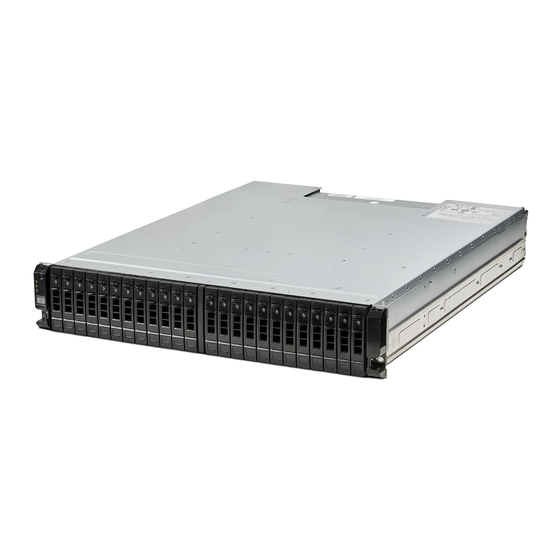
Page 21: 2U24 Enclosure System - Dimetric Front Orientation
NOTE: Please refer to “Enclosure variants” (page 23) for details about various 2U24 enclosure options. Figure 3 2U24 enclosure system – dimetric front orientation Figure 4 2U24 enclosure system – dimetric rear orientation The 2U24 controller enclosure above is equipped with dual-controllers (4-port SAS model shown). Supercapacitor pack... -
Page 22: 5U84 Enclosure System - Dimetric Front Orientation
NOTE: Please refer to “Enclosure variants” (page 23) for details about various 5U84 enclosure options. Figure 5 5U84 enclosure system – dimetric front orientation Figure 6 5U84 enclosure system – dimetric rear orientation The 5U84 controller enclosure above is equipped with dual-controllers (4-port FC/iSCSI model shown). System overview... -
Page 23: Enclosure Variants
Enclosure variants The 2U chassis can be configured as a controller enclosure (5005, 4005) or an expansion enclosure (J1212/J1224) as shown in Table 3 Table 4. The 5U chassis can be configured as a controller enclosure (5005, 4005) or an expansion enclosure (J1284) as shown in Table IMPORTANT: The 2U and 5U core products–including key components and CRUs–are described herein. -
Page 24: 2U Enclosure Core Product
NOTE: The enclosure core product definitions follow. • “2U enclosure core product” for the 2U12 and 2U24 form factor. • “5U enclosure core product” for the 5U84 form factor. • IOMs are used in 2U and 5U chassis, and are described in “Controller modules”... -
Page 25: 2U Enclosure Rear Panel
2U enclosure rear panel Numeric designators on PCMs and alphabetic designators on IOMs indicate slot sequencing for modules used in 2U enclosures. PCM and IOM modules are available as CRUs. The 5005 and 4005 RBODs use 4-port controller modules. The 5005/4005 Series RBODs support the J1212/J1224/J1284 EBODs for optionally adding storage. -
Page 26: Expansion Module Detail (J1212/J1224/J1284)
Serial ports Ethernet CNC ports (service only) SAS port port USB port Reset (typical 2 places) Illustration is under construction Figure 12 4-port FC/iSCSI controller module detail (5005/4005 Series) Figure 13 shows SAS host interface ports that ship configured with 12Gb/s HD mini-SAS (SFF-8644) external connectors. Serial ports Ethernet SAS ports... -
Page 27: 2U Enclosure Chassis
Power cooling module Figure 15 shows the power cooling module (PCM) used in controller enclosures and optional expansion enclosures. The example shows a PCM oriented for use in the left PCM slot of the enclosure rear panel. PCM OK LED AC Fail LED Fan Fail LED DC Fail LED... -
Page 28: 5U Enclosure Core Product
Figure 16 2U12 enclosure chassis – dimetric front orientation Figure 17 2U24 enclosure chassis – dimetric front orientation NOTE: Either 2U chassis can be configured as a controller enclosure or as an optional expansion enclosure for adding storage. 5U enclosure core product The 5U chassis consists of a sheet metal enclosure, integrated PCBs, and a module runner system. -
Page 29: 5U Enclosure Front Panel
• Two IOMs: 2 x SBB-compliant interface slots. • Up to 84 DDIC modules populated within two drawers (42 DDICs per drawer; 14 DDICs per row). TIP: The 5U84 does not ship with DDICs installed. DDICs ship in a separate container, and must be installed into the enclosure drawers during product installation and setup. -
Page 30: 5U Enclosure Rear Panel
Figure 19 shows a plan view of an enclosure drawer that is accessed from the enclosure front panel. The view is scaled and rotated -90º about the vertical axis to better fit the page, and the conceptual graphics are simplified for clarity. IMPORTANT: Drawer sideplanes—also known as side cards—can be hot-swapped as field-replaceable units (FRUs). -
Page 31: Power Supply Unit (Psu) Detail
С С Figure 22 5U84 expansion enclosure – rear panel components 5U rear panel components Controller modules The 5U84 controller enclosure uses the same IOMs used by 2U12 and 2U24 enclosures. See “Controller modules” (page 25). See also Figure 12 Figure 13 (page 26). -
Page 32: 5U Enclosure Chassis
Fan cooling module Figure 24 shows the fan cooling module (FCM) used in 5U controller enclosures and optional 5U expansion enclosures. Release latch Handle Module OK Fan Fault Figure 24 Fan cooling module (FCM) detail 5U enclosure chassis The 5U chassis consists of a sheet metal enclosure with an integrated midplane PCB, module runner system, and two drawers for drive modules. -
Page 33: Operator's (Ops) Panel
Safety features: • To reduce the possibility of toppling, only one drawer can be open at a time. • The drawer locks into place when fully opened and extended. To reduce pinching hazards, two latches must be released before the drawer can be pushed back into the drawer slot within the enclosure. Power and data are sent via three baseplanes and two sideplanes. -
Page 34: 5U Enclosure Ops Panel
Mute (not used) System Power Module Fault Identity Ops panel functions (see left ear on 2U front panel) Status System Power On/Standby Constant green: positive indication Constant amber: fault present Module Fault Constant or blinking amber: fault present Identity Blue: power on (5s) test state Unit Identification Display Green (seven segment display: enclosure sequence) Thermal sensor... -
Page 35: Leds: Ops Panel - 5U Enclosure Front Panel
• Unit Identification Display (UID) • Mute/Input button • Power On/Standby LED (green/amber) • Module Fault LED (amber) • Logical Status LED (amber) • Top Drawer Fault LED (amber) • Bottom Drawer Fault LED (amber) The Ops panel is an integral part of the chassis CRU, and is not replaceable on site. Input Switch (not used) Power On/Standby Module Fault... -
Page 36: Power Cooling Module - 2U Enclosures
Logical Status LED (amber) This LED indicates a change of status or fault from something other than the enclosure management system. This may be initiated from the controller module or an external HBA. The indication is typically associated with a DDIC and LEDs at each disk position within the drawer, which help to identify the DDIC affected. -
Page 37: System Airflow
PCMs are hot-pluggable, and replacement should only take a few seconds to do. Replacement must be completed as soon as possible after the removal of the defective PCM to avoid a thermal exception. The replacement procedure should be completed within an absolute maximum of 2 minutes. IMPORTANT: Operation of the enclosure with any modules missing will disrupt the airflow, and the disks will not receive sufficient cooling. -
Page 38: Fan Cooling Module - 5U Enclosures
Fan cooling module – 5U enclosures The five fan cooling modules (FCM) at the rear of the enclosure maintain all system components below their maximum temperature, assuming the ambient temperature is below 35ºC. Fan speed within the FCMs is governed by the controller modules. -
Page 39: Controller And Expansion Modules
Controller and expansion modules This section describes the IOMs used in 12Gb/s storage enclosures. They are mechanically and electrically compliant to the latest SBB v2.1 specification. The dimetric rear orientation in Figure 31 shows a 4-port FC/iSCSI controller module aligned for use in the top controller module slot located on the 2U enclosure rear panel. -
Page 40: Leds: 5005/4005 Series Fc/Iscsi Controller Modules (Fc And 10Gbe Sfps)
= iSCSI (2) = FC (1) LED Description Definition Host 4/8/16Gb FC Off — No link detected. Link Status/ Green — The port is connected and the link is up. Link Activity Blinking green — The link has I/O activity. Host 10GbE iSCSI Off —... -
Page 41: Leds: 5005/4005 Series Iscsi Controller Module (1Gb Rj-45 Sfps)
= FC (1) = iSCSI (2) LED Description Definition Not used in example The FC SFP is not shown in this example. Host 1Gb iSCSI Off — No link detected. Link Status/ Green — The port is connected and the link is up. Link Activity Blinking green —... -
Page 42: Leds: 5005/4005 Series Sas Controller Module (Hd Mini-Sas)
1 = HD mini-SAS host ports LED Description Definition Host 12Gb SAS Green — The port is connected and the link is up. Link Status/ Amber — Partial link exists (one or more lanes down). Link Activity Blinking green or amber — Host link activity is detected. Green —... -
Page 43: Controller Failure When A Single-Controller Is Operational
When a controller is shut down or otherwise rendered inactive—its Link Status LED remains illuminated— falsely indicating that the controller can communicate with the host. Though a link exists between the host and the chip on the controller, the controller is not communicating with the chip. To reset the LED, the controller must be power-cycled. Cache Status LED details Power on/off behavior The storage enclosure's unified CPLD provides integrated Power Reset Management (PRM) functions. -
Page 44: 12Gb/S Expansion Module Leds
If the controller has failed or does not start, is the Cache Status LED on/blinking? Answer Action No, the Cache LED status is off, and the controller If the problem persists, replace the controller module. does not boot. No, the Cache Status LED is off, and the controller The system has flushed data to disks. -
Page 45: Disk Drive Module
The following table provides companion data for the figure above relative to LED states for A/B/C SAS port expansion. Table 8 LEDs: J1212/J1224/J1284 expansion activity states Condition Activity (Green) Fault (Amber) No cable present Cable present: all links up/no activity Cable present: all links up/with aggregate port activity Blinking Critical fault: Any fault causing operation of the cable to cease or fail to start... -
Page 46: Dual Path Lff 3.5" Disk Drive Carrier Modules
NOTE: Dimetric pictorial views of supported drive carriers are provided in the following illustrations. Modules are shown oriented for insertion into disk drive slots located on the enclosure front panel. 3.5" SAS drive Figure 36 Dual path LFF 3.5" disk drive carrier modules Figure 37 Dual path SFF 2.5"... -
Page 47: Drive Status Indicators
Drive status indicators Green and amber LEDs on the front of each drive carrier module indicate disk drive status. The SEP controls these LEDs. “Disk drive carrier module LEDs” (page 84) describes the LED states. Dummy drive carrier modules Dummy drive carrier modules, also known as drive blanks, are provided in 3.5" (2U12) and 2.5" (2U24) form factors. They must be installed in empty disk drive slots to create a balanced air flow. -
Page 48: Ddic With Adapter And 2.5" Disk
Figure 41 shows a DDIC with an adapter and a 2.5" disk. Figure 41 DDIC with adapter and 2.5" disk The DDIC features a latch button (center of top view) and a slide latch with arrow label (left of latch button). These features allow you to install and secure the DDIC into the disk slot within the drawer. -
Page 49: Enclosure Management
Figure 42 Pictorial view of 5U84 enclosure drawer fully populated with DDICs Enclosure management SBB IOMs actively manage the enclosure. Each module has a SAS expander with its own storage enclosure processor (SEP) that provides a SES target for a host to interface to through the ANSI SES Standard. If one of these modules fails, the other module will continue to operate. -
Page 50: Installation
Installation Installation checklist This chapter shows how to plan for and successfully install your enclosure system into an industry standard 19-inch rack cabinet. CAUTION: To install the system, use only the power cords supplied, or power cables that match the specification quoted in “AC power cords”... -
Page 51: Planning For Installation
Planning for installation Before beginning the enclosure installation, familiarize yourself with the system configuration requirements. The figures listed below show the locations for each plug-in module: • 2U12 front panel: see Figure 7 (page 24) • 2U24 front panel: see Figure 8 (page 24) •... -
Page 52: Preparing The Site And Host Server
Make sure you wear an effective anti-static wrist or ankle strap and obey conventional ESD precautions when touching modules and components. Do not touch midplane, motherboard, or module connectors. See also “ESD precautions” (page 107). This section provides important preparation requirements and handling procedures for use during product installation. -
Page 53: Required Tools
2U enclosures are supplied with the midplane PCB and all plug-in modules installed. For information about plug-in module replacement, see “Module removal and replacement”. Dummy drive carriers must be installed in unused drive slots. 3. The unpacking procedure pertaining to the 5U84 is shown in Figure CAUTION: The enclosure does not include DDICs, but all rear panel modules are installed. -
Page 54: Requirements For Rackmount Installation
Requirements for rackmount installation You can install the enclosure in an industry standard 19-inch cabinet capable of holding 2U form factors. • Minimum depth: 707 mm (27.83") from rack posts to maximum extremity of enclosure (includes rear panel cabling and cable bend radii). -
Page 55: Installing The 5U Enclosure
3. Install the enclosure into the rack: a. Lift the enclosure and align it with the installed rack rails, taking care to ensure that the enclosure remains level. b. Carefully insert the chassis slides into the rack rails and push fully in. c. -
Page 56: Fde Considerations
CAUTION: Use only power cords supplied, or power cords that comply with the specifications in Table 43 (page 143) CAUTION: Once the enclosure is installed in the rack, dispose of the lifting straps. Due to the difficulty in attaching the straps once the enclosure is installed into the rack, the straps are not suitable for removing the enclosure from the rack. -
Page 57: Connecting The Controller Enclosure And Optional Expansion Enclosures
5U84 expansion enclosures in the same storage system. Cable requirements for expansion enclosures When adding storage, use only Seagate or OEM-qualified cables, and observe the following guidelines: • When installing SAS cables to expansion modules, use only supported HD mini-SAS x4 cables. -
Page 58: Cabling Connections Between A 2U Controller Enclosure And 2U Expansion Enclosures
Controller A Controller A Controller B Controller B Add enclosures up to maximum (10) Add enclosures up to maximum (10) Reverse cabling Straight-through cabling Figure 47 Cabling connections between a 2U controller enclosure and 2U expansion enclosures The diagram above (left) shows reverse cabling of a 5005/4005 Series dual-controller 2U enclosure and supported 2U drive enclosures configured with dual expansion modules. -
Page 59: Cabling Connections Between A 5U Controller Enclosure And 5U Expansion Enclosures-Reverse
Controller A Controller B Reverse cabling Figure 48 Cabling connections between a 5U controller enclosure and 5U expansion enclosures–reverse Figure 48 Figure 49 show maximum configuration cabling for a 5005/4005 Series 5U controller enclosure with 5U expansion enclosures (4 enclosures including the controller enclosure). NOTE: See also Figure 14 (page 26) and the IMPORTANT entry beneath that figure. -
Page 60: Cabling Connections Between A 2U Controller Enclosure And 5U Expansion Enclosures-Reverse
Controller A Controller B Reverse cabling Figure 50 Cabling connections between a 2U controller enclosure and 5U expansion enclosures–reverse Figure 50 Figure 51 show maximum configuration cabling for a 5005/4005 Series 5U controller enclosure with 5U expansion enclosures (4 enclosures including the controller enclosure). NOTE: See also Figure 14 (page 26) and the IMPORTANT entry beneath that figure. -
Page 61: Power Cord Connection
Power cord connection Connect a power cord from each PCM or PSU on the enclosure rear panel to the PDU (power distribution unit) as shown in the illustrations below (4-port SAS models are shown in the examples). Controller Enclosure Power Distribution Units (AC UPS shown) Figure 52 Typical AC power cord connection from PDU to PCM (2U) Controller Enclosure Power Distribution Units (AC UPS shown) -
Page 62: Host System Requirements
“Connecting a management host on the network” (page 69). The FC and iSCSI product models can be licensed to support replication, whereas the HD mini-SAS models cannot. Use only Seagate or OEM-qualified cables for host connection: • Qualified Fibre Channel SFP and cable options •... -
Page 63: Cnc Technology
TIP: See the topic about configuring system settings in the Storage Management Guide to initially configure the system, or change system configuration settings (such as Configuring host ports). CNC technology The 5005/4005 Series FC/iSCSI models use Converged Network Controller (CNC) technology, allowing you to select the desired host interface protocol(s) from the available FC or iSCSI host interface protocols supported by the system. -
Page 64: Sas Protocol
The 10GbE iSCSI ports are used in either of two capacities: • To connect two storage systems through a switch for use of replication. • For attachment to 10GbE iSCSI hosts directly, or through a switch used for the 10GbE iSCSI traffic. The first usage option requires valid licensing for the replication feature, whereas the second option requires that the host computer supports Ethernet, iSCSI, and optionally, multipath I/O. -
Page 65: Fibre Channel Host Connection
Fibre Channel host connection To connect controller modules supporting (4/8/16Gb) FC host interface ports to a server HBA or switch, using the controller’s CNC ports, select a qualified FC SFP option. Qualified options support cable lengths of 1 m (3.28'), 2 m (6.56'), 5 m (16.40'), 15 m (49.21'), 30 m (98.43'), and 50 m (164.04') for OM4 multimode optical cables and OM3 multimode FC cables, respectively. -
Page 66: Connecting Hosts: 5005/4005 Series 2U Direct Attach - One Server/ One Hba/ Dual Path
NOTE: In the examples that follow, a single diagram represents CNC and SAS host connections for 5005 and 4005 respectively. The location and sizes of the host ports are very similar. Blue cables show controller A paths and green cables show controller B paths for host connection. Controller enclosure Server Figure 54 Connecting hosts: 5005/4005 Series 2U direct attach –... -
Page 67: Connecting Hosts: 5005/4005 Series 2U Direct Attach - Four Servers/ One Hba Per Server/ Dual Path
Server 1 Server 2 Controller enclosure Server 4 Server 3 Figure 58 Connecting hosts: 5005/4005 Series 2U direct attach – four servers/ one HBA per server/ dual path Server 2 Server 1 Server 4 Server 3 Controller enclosure Figure 59 Connecting hosts: 5005/4005 Series 5U direct attach – four servers/ one HBA per server/ dual path Switch attach A switch attach solution—or SAN—places a switch between the servers and the controller enclosures within the storage system. -
Page 68: Connecting Hosts: 5005/4005 Series 2U Switch Attach - Two Servers/ Two Switches
Server 1 Server 2 Switch A Switch B Controller enclosure Figure 60 Connecting hosts: 5005/4005 Series 2U switch attach – two servers/ two switches Server 2 Server 1 Switch B Switch A Controller enclosure Figure 61 Connecting hosts: 5005/4005 Series 5U switch attach – two servers/ two switches Installation... -
Page 69: Connecting A Management Host On The Network
Server 2 Server 1 Server 3 Server 4 Controller enclosure Figure 62 Connecting hosts: 5005/4005 Series 2U switch attach – four servers/ multiple switches/ SAN fabric Server 1 Server 2 Server 4 Server 3 Controller enclosure Figure 63 Connecting hosts: 5005/4005 Series 5U switch attach – four servers/ multiple switches/ SAN fabric Connecting a management host on the network The management host directly manages storage systems out-of-band over an Ethernet network. -
Page 70: Updating Firmware
Updating firmware After installing the hardware and powering on the storage system components for the first time, verify that the controller modules, expansion modules, and disk drives are using the current firmware release. Using the Storage Management Console, in the System topic, select Action > Update Firmware. The Update Firmware panel opens. -
Page 71: Terminal Emulator Display Settings
Use the CLI commands described in the steps below to set the IP address for the network port on each controller module. Once new IP addresses are set, you can change them as needed using the SMC. Be sure to change the IP address before changing the network configuration. - Page 72 Table 12 Terminal emulator connection settings (continued) Parameter Value Stop bits Flow control None 1-Your server or laptop configuration determines which COM port is used for Disk Array USB Port. 2-Verify the appropriate COM port for use with the CLI. 5.
-
Page 73: Change The Cnc Port Mode
IMPORTANT: When configuring an iSCSI system or a system using a combination of FC and iSCSI SFPs, do not restart the Management Controller or exit the terminal emulator session until configuring the CNC ports as described in “Change the CNC port mode” (page 73). -
Page 74: Connecting Two Storage Systems To Replicate Volumes
Connecting two storage systems to replicate volumes Replication is a licensed feature for disaster recovery. This feature performs asynchronous replication of block-level data from a volume in a primary system to a volume in a secondary system by creating an internal snapshot of the primary volume, and copying the changes to the data since the last replication to the secondary system via FC or iSCSI links. -
Page 75: Cabling For Replication
Cabling for replication This section shows example replication configurations for CNC-based controller enclosures. NOTE: Simplified versions of controller enclosures are used in cabling illustrations to show host ports used for I/O or replication, given that only the external connectors used in the host interface ports differ. •... -
Page 76: Connecting Two 5005/4005 Series 2U Storage Systems For Replication: Multiple Servers/One Switch/One Location
Controller enclosure Controller enclosure Switch To host server(s) Figure 65 Connecting two 5005/4005 Series 2U storage systems for replication: multiple servers/one switch/one location Controller enclosure Controller enclosure Switch To host server(s) Figure 66 Connecting two 5005/4005 Series 5U storage systems for replication: multiple servers/one switch/one location Figure 67 (2U) and Figure 68 (page 77) -
Page 77: Connecting Two 5005/4005 Series 5U Storage Systems For Replication: Multiple Servers/Switches/One Location
Controller enclosure Controller enclosure I/O switch I/O switch Replication switch To host servers To host servers Figure 68 Connecting two 5005/4005 Series 5U storage systems for replication: multiple servers/switches/one location Multiple servers/different networks/multiple switches Figure 69 (2U) and Figure 70 (5U) each show the rear panel of two enclosures with I/O and replication occurring on different networks. - Page 78 The diagrams shown in Figure 69 Figure 70 represent two branch offices cabled to enable disaster recovery and backup. In case of failure at either the local site or the remote site, you can fail over the application to the available site. Installation...
-
Page 79: Operation
Operation Before you begin Before powering on the enclosure system, make sure that all modules are firmly seated in their correct slots. Verify that you have successfully completed the sequential “Installation Checklist” instructions in Table 9 (page 50). Once you have completed steps 1 through 10, you can access the management interfaces using your web-browser to complete the system setup. -
Page 80: Operator's (Ops) Panel Leds
NOTE: Guidelines for consideration when powering enclosures on and off • Remove the AC cord before inserting or removing a PCM (2U) or PSU (5U). • Move the PCM or PSU switch to the off position before connecting or disconnecting the AC power cord. •... -
Page 81: Accessing The Smc
Accessing the SMC Upon completing the hardware installation, you can access the controller module’s web-based management interface—Storage Management Console (SMC)—to configure, monitor, and manage the storage system. Invoke your web browser and enter the IP address of the controller module’s network port in the address field, then press Enter. To sign-in to the SMC, use the default user name manage and password !manage. -
Page 82: Troubleshooting And Problem Solving
They are not intended to be used as troubleshooting procedures for configured systems using production data and I/O. NOTE: For further troubleshooting help after setup, and when data is present, see seagate.com/support-home. Overview The enclosure system includes a Storage Enclosure Processor (SEP) and associated monitoring and control logic to enable it to diagnose problems with the enclosure’s power, cooling, and drive systems. -
Page 83: 2U Enclosure Leds
2U enclosure LEDs 580W PCM LEDs Under normal conditions, the PCM OK LEDs will be a constant green. See also Figure 28 (page 36). When a fault occurs, the colors of the LEDs will display as shown in the following table. Table 13 PCM LED states PCM OK Fan Fail... -
Page 84: Disk Drive Carrier Module Leds
• If the above actions do not resolve the fault, contact Seagate for assistance. Disk drive carrier module LEDs Disk drive status is monitored by a green LED and an amber LED mounted on the front of each drive carrier module, as... -
Page 85: Iom Leds
2.5-inch disk 3.5-inch disk Disk Activity LED Disk Fault LED Disk Fault LED Disk Activity LED Activity LED (Green) Fault LED (Amber) Status/condition* Off (disk module/enclosure) Not present Blink off with activity Blinking: 1s on/1s off Identify 1 down: Blink with activity Drive link (PHY lane) down 2 down: Off Fault (leftover/failed/locked-out) -
Page 86: 5U Enclosure Leds
Table 15 Controller module LED states (continued) CRU OK CRU Fault External host port (Green) (Amber) activity (Green) Status Blinking External host port connection – activity Blinking System is booting Actions: • If the CRU OK LED is blinking, wait for the system to boot. •... -
Page 87: Fan Cooling Module Leds
Table 17 PSU LED states (continued) CRU Fail AC Missing Power (Amber) (Amber) (Green) Status Mains AC present, switch on. This PSU is providing power. Blinking AC power present, PSU in standby (other PSU is providing power). Blinking Blinking PSU firmware download in progress. AC power missing, PSU in standby (other PSU is providing power). -
Page 88: Ddic Led
Table 20 Drawer LED descriptions Status/description Sideplane OK/ Green if the sideplane card is working and there are no power problems. Power Good Drawer Fault Amber if a drawer component has failed. If the failed component is a disk, the LED on the failed DDIC will light amber. -
Page 89: Iom Leds
Each DDIC has a single Drive Fault LED. A disk drive fault is indicated if the Drive Fault LED is lit amber. In the event of a disk failure, follow the procedure in “Replacing a DDIC” (page 127). IOM LEDs NOTE: IOM CRUs are common to the 2U and 5U enclosures. -
Page 90: Pcm Faults
PCM Faults Symptom Cause Recommended action Ops panel Module Fault LED is amber Any power fault Verify AC mains connections to PCM are live Fan Fail LED is illuminated on PCM Fan failure Replace PCM 1-See Figure 26 (page 34) for visual reference of Ops panel LEDs. -
Page 91: Troubleshooting 5U Enclosures
Fault isolation methodology Seagate 5005/4005 Series storage systems provide many ways to isolate faults. This section presents the basic methodology used to locate faults within a storage system, and to identify the pertinent CRUs affected. As noted in “Accessing the SMC”... -
Page 92: Basic Steps
will notify you when a problem occurs that is at or above the configured severity (see the Configuring event notification topic within the Storage Management Guide). With event notification configured and enabled, you can follow the recommended actions in the notification message to resolve the problem, as further discussed in the options presented below. -
Page 93: Performing Basic Steps
Performing basic steps You can use any of the available options described above in performing the basic steps comprising the fault isolation methodology. Gather fault information When a fault occurs, it is important to gather as much information as possible. Doing so will help you determine the correct action needed to remedy the fault. -
Page 94: Correcting Enclosure Ids
• Power cycle the system • Make sure the power cord is properly connected, and check the power source to which it is connected • Check the event log for errors Correcting enclosure IDs When installing a system with drive enclosures attached, the enclosure IDs might not agree with the physical cabling order. - Page 95 IMPORTANT: Do not perform more than one step at a time. Changing more than one variable at a time can complicate the troubleshooting process. Host-side connection troubleshooting featuring CNC ports The procedure below applies to controller enclosures employing small form factor pluggable (SFP) transceiver connectors in 4/8/16Gb/s FC, 10GbE iSCSI, or 1Gb/s iSCSI host interface ports.
- Page 96 Is the host link status/link activity LED on? Yes – You have isolated the fault to the HBA. Replace the HBA. No – It is likely that the controller module needs to be replaced. 12. Move the cable and SFP back to its original port. Is the host link status/link activity LED on? No –...
-
Page 97: Isolating A Controller Module Expansion Port Connection Fault
Isolating a controller module expansion port connection fault During normal operation, when a controller module’s expansion port is connected to a drive enclosure, the expansion port status LED is green. If the connected port’s expansion port LED is off, the link is down. Use the following procedure to isolate the fault. -
Page 98: Replication Setup And Verification
Replication setup and verification After storage systems are cabled for replication, you can use the SMC to prepare for using the replication feature. Alternatively, you can use SSH or telnet to access the IP address of the controller module and access the replication feature using the CLI. -
Page 99: Diagnostics For Replication Setup: Using The Replication Feature
Diagnostic steps for replication setup The tables in this subsection show menu navigation for virtual replication using the SMC. Can you successfully use the replication feature? Answer Possible reasons Action System functioning properly. No action required. The replication feature is not licensed Verify licensing of the optional feature per system: on each controller enclosure used for •... -
Page 100: Diagnostics For Replication Setup: Creating A Replication Set
Can you create a replication set? Answer Possible reasons Action System functioning properly. No action required. On controller enclosures equipped with If using CHAP (Challenge-Handshake Authentication Protocol), see iSCSI host interface ports, replication the topics about configuring CHAP and working in replications set creation fails due to use of CHAP. -
Page 101: Continuous Operation During Replacement
Has a replication run successfully? Answer Possible reasons Action System functioning properly. No action required. Last Successful Run shows N/A. • In the Volumes topic, click on the volume that is a member of the replication set. Select the Replication Sets table. ... -
Page 102: Customer-Replaceable Units
Figure 73 (page 106) for pictorial views of IOM CRUs used in the different enclosure form factors supported by 5005/4005 Series. Table 27 5005 Series enclosure models 5005 Series: 4-port controller enclosure matrix–2U 2.5" (SFF) 24-drive controller enclosures 3.5" (LFF) 12-drive controller enclosures... -
Page 103: Crus Addressing 2U 12-Drive Chassis
CRUs addressing 2U 12-drive chassis Table 30 5005/4005 Series product components for 2U 12-drive chassis Item Enclosure component description Disk drive (LFF) a) 3.5" disk drive module (disks of differing type/speed and storage capacity: SAS, SSD) b) Dummy drive carrier module (blank to maintain optimum air flow within enclosure) Ear components (not customer replaceable) a) Left ear assembly b) Right ear assembly... -
Page 104: Crus Addressing 2U 24-Drive Chassis
CRUs addressing 2U 24-drive chassis Table 31 5005/4005 Series product components for 2U 24-drive chassis Item Enclosure component description Disk drive (SFF) a) 2.5" disk drive module (disks of differing type/speed and storage capacity: SAS, SSD) b) Dummy drive carrier module (blank to maintain optimum air flow within enclosure) Ear components (not customer replaceable) a) Left ear assembly b) Right ear assembly... -
Page 105: Crus Addressing High-Density 5U 84-Drive Chassis
CRUs addressing high-density 5U 84-drive chassis Table 32 5005/4005 Series product components for 5U 84-drive chassis Item Enclosure component description Disk drive in carrier (DDIC) LFF (DDICs must be installed into drawers after delivery) a) 2.5" disk with 3.5" adapter (disks of differing type/speed and storage capacity: SAS, SSD) b) 3.5"... -
Page 106: Sbb Ioms Used In 5005/4005 Series Storage Enclosures
4-port FC/iSCSI controller module 4-port SAS controller module С 3-port expansion module Figure 73 SBB IOMs used in 5005/4005 Series storage enclosures Troubleshooting and problem solving... -
Page 107: Module Removal And Replacement
Module removal and replacement Overview This chapter provides procedures for replacing CRUs (customer-replaceable units), including precautions, removal instructions, installation instructions, and verification of successful installation. Each procedure addresses a specific task. Certain procedures refer to related documentation. See “Related documentation” (page 14) for a list of these documents and where to find them online. -
Page 108: Cru Replacement For 2U Chassis
If you do not have any of the suggested equipment for proper grounding, have an authorized technician install the part. For more information about static electricity or assistance with product installation, contact customer support. For additional information, see seagate.com/support-home. CRU replacement for 2U chassis NOTE: Unless noted otherwise within a passage pertaining to a particular CRU, the replacement procedure should be completed within two minutes of the removal of a defective module. - Page 109 3. Switch off the faulty PCM, and disconnect the power supply cable. 4. If replacing a single PCM via hot-swap, proceed to step 5. If replacing both PCMs, verify that the enclosure was shut down using management interfaces, and that the enclosure is powered off.
-
Page 110: Installing A Pcm
NOTE: The remove PCM illustrations show a chassis configured as a 4-port SAS controller enclosure, The procedure applies to all 2U controller enclosures and expansion enclosures. 9. If replacing two PCMs, repeat steps 5 through 8, being mindful of the illustrations TIP on page 108. -
Page 111: Removing A Lff Drive Carrier Module
TIP: The illustrations show disk module replacement within the drive slots as you view the enclosure front panel. Removing a LFF drive carrier module 1. Press the latch in the carrier handle towards the handle hinge to release the carrier handle as shown below. Figure 76 Removing a LFF disk drive module (1 of 2) 2. -
Page 112: Installing A Lff Drive Carrier Module
CAUTION: To ensure optimal cooling throughout the enclosure, dummy drive carrier modules must be fitted to all unused drive slots. See also Figure 39 (page 47). Installing a LFF drive carrier module CAUTION: A drive carrier module cannot be installed if its anti-tamper lock is activated outside the enclosure. See step 1 of the procedure described on page... -
Page 113: Using The Anti-Tamper Locks
4. Cam the drive carrier home. The camming foot on the carrier will engage into a slot in the enclosure. Continue to push firmly until the handle fully engages. You should hear a click as the latch handle engages and holds the handle closed. Figure 80 Installing a LFF drive carrier module (2 of 2) 5. -
Page 114: Removing A Sff Drive Carrier Module
Removing a SFF drive carrier module The removal/replacement procedure for SFF drive carrier modules is basically the same as for LFF models, except that the SFF carriers are mounted vertically. 1. Press the latch in the carrier handle downward to release the carrier handle so that it can revolve outward as shown below. Figure 82 Removing a SFF disk drive module (1 of 2) 2. -
Page 115: Installing A Sff Drive Carrier Module
Installing a SFF drive carrier module 1. If the anti-tamper lock is engaged, unlock it per the instructions provided in “Using the anti-tamper locks” (page 113). 2. Release the carrier handle by pressing the latch in the handle downwards, and opening the hinged handle as shown Figure 84 (page 115). -
Page 116: Replacing A Dummy Drive Carrier
4. Cam the carrier home. The camming lever on the carrier will engage into the a slot in the enclosure. Continue to push firmly until the handle fully engages. You should hear a click as the latch handle engages and holds the handle closed. Figure 86 Installing a SFF drive carrier module (2 of 2) 5. -
Page 117: Before You Begin
TIP: The illustrations show IOM module replacement within the top slot (A) as you view the enclosure rear panel. To replace an IOM in the bottom slot (B), you would first rotate the module 180º about its longitudinal axis, so that it properly aligns with its connectors on the back of the midplane. -
Page 118: Stopping I/O
• As an alternative to using the SMC, you can run the CLI show system command to view the health of the system and its components. If any component has a problem, the system health will be Degraded, Fault, or Unknown. If you discover a problem component, follow the actions in its Health Recommendations field to resolve the problem. -
Page 119: Removing An Iom
6. Select Yes to continue; otherwise, select No. If you selected Yes, a message describes shutdown activity. NOTE: If an iSCSI port is connected to a Microsoft Windows host, the following event is recorded in the Windows event log: Initiator failed to connect to the target. NOTE: See the Storage Management Guide for additional information. -
Page 120: Iom Latch Operation Detail
Figure 87 IOM latch operation detail 5. Swing the latch handle open as shown in detail No.2 within Figure 87 Figure 4-port FC/iSCSI controller module shown Figure 88 Removing an IOM 6. Grip the latch handle and ease the IOM forward from the slot as shown in detail No.2 within Figure NOTE: The illustration above shows a 4-port controller module of model type SAS. -
Page 121: Installing An Iom
Installing an IOM See CAUTION bullets regarding electrostatic discharge and anti-static protection on page 107. CAUTION: If passive copper cables are connected, the cable must not have a connection to a common ground/earth point. NOTE: When performing the following procedure, refer to Figure 88 (page 120) while ignoring the directional arrow. -
Page 122: Replacing A 2U Storage Enclosure Chassis
CRU modules from a damaged chassis and installing them into a replacement chassis. IMPORTANT: The 5005/4005 Series enclosures using 2U12 or 2U24 chassis are described in “5005 Series enclosure models” (page 102) “4005 Series enclosure models” (page 102). -
Page 123: Removing A Damaged 2U Storage Enclosure Chassis From The Rack
Table 33 Replacing a 2U storage enclosure chassis and installing its CRUs To accomplish this sequential process See the following procedures Facing the front of the 2U enclosure, remove the “Removing a LFF drive carrier module” (page 111), or disk modules from the damaged chassis and place “Removing a SFF drive carrier module”... -
Page 124: Installing The Replacement 2U Storage Enclosure In The Rack
NOTE: Do not remove the ear components from the failed chassis: integrated ear components and covers are provided with the replacement chassis CRU. 3. Maintaining a level position, carefully slide the enclosure chassis from the rack. 4. Place the chassis on a static-protected work surface near the replacement enclosure chassis, with the removed disk drive modules and screws. - Page 125 To perform a rescan using the CLI, enter the following command: rescan To perform a rescan using the SMC: a. Verify that both controllers are operating normally. b. In the System topic, select Action > Rescan Disk Channels. c. Select Rescan. Using LEDs View LEDs on the enclosure front and rear panels.
-
Page 126: Cru Replacement For 5U Chassis
CRU replacement for 5U chassis NOTE: Unless noted otherwise within a passage pertaining to a particular CRU, the replacement procedure should be completed within two minutes of the removal of a defective module. Accessing drawers To observe or replace a DDIC, you must open the drawer in which it resides. The top drawer (Drawer 0) and the bottom drawer (Drawer 1) are accessed from the enclosure front panel. -
Page 127: Closing A Drawer
3. Pull the drawer outward until it locks at the drawer stops as shown in Figure The drawer is shown empty, which is how the enclosure is delivered. Slide rail latch inset Figure 91 Opening a drawer (2 of 2) IMPORTANT: The drawer must not remain open for more than two minutes whilst the enclosure is powered on. -
Page 128: Removing A Ddic (1 Of 2)
3. Locate the DDIC to be replaced using any of the methods listed in step 1 above. 4. On the face of the DDIC, push the latch button in the direction shown in Figure 92 (page 128) to unlock the DDIC from its seated position in the slot. -
Page 129: Installing A Ddic
Installing a DDIC IMPORTANT: Failed disks must be replaced with approved disks. Contact your service provider for details. 1. Open the relevant drawer per the instructions provided in “Opening a drawer” (page 126). 2. Align the DDIC with the target disk slot as shown in Figure 93 (page 128) and insert it into the disk slot. -
Page 130: Installation Guidelines
Installation guidelines The recommended order for partially populating drives in the 5U84 enclosure optimizes the airflow through the chassis. Please reference the following illustrations: • Figure 18 (page 29) shows location and indexing of drawers accessed from the enclosure front panel. •... - Page 131 5. If replacing both PSUs, verify that the enclosure was shut down using management interfaces, and that the enclosure is powered off. 6. Verify that the power cord is disconnected. 7. Refer to Figure 95 (page 131) when performing this step: a.
-
Page 132: Installing A Psu
Installing a PSU 1. Ensure that the PSU is switched off. If replacing both PSUs, the enclosure must be powered off via an orderly shutdown using the management interfaces. 2. Orient the PSU for insertion into the target slot on the enclosure rear panel, as shown in Figure 3. -
Page 133: Installing An Fcm
Figure 98 Removing an FCM (2 of 2) IMPORTANT: The FCM slot must not be empty for more than 2 minutes while the enclosure is powered. Installing an FCM 1. You can hotswap the replacement of a single FCM; however, if replacing multiple FCMs, the enclosure must be powered off via an orderly shutdown using the management interfaces. -
Page 134: Removing An Iom
Removing an IOM IMPORTANT: Considerations for removing controller modules: • In a dual-controller environment, you may hot-swap a single controller module in an operational enclosure, provided you first shut down the faulty controller using the SMC or the CLI. • In a dual-controller environment—if replacing both controller modules—you must adhere to the instructions provided in “Before you begin”... -
Page 135: Installing An Iom
NOTE: The illustrations above and below show a 4-port controller module of type FC/iSCSI. However, the procedure applies to all IOMs used in 5U84 enclosures. They all use the same latch mechanism, but feature different face plate geometry as shown in Figure 73 (page 106). -
Page 136: Replacing A 5U Storage Enclosure Chassis
NOTE: In a dual-controller system in which PFU is enabled, when you update the firmware on one controller, the system automatically updates the partner controller. Replacing a 5U storage enclosure chassis The controller enclosure or expansion enclosure chassis replacement procedure replaces a damaged 5U chassis CRU. The procedure includes removing all CRU modules from a damaged chassis and installing them into a replacement chassis. -
Page 137: Preparing To Remove A Damaged 5U Storage Enclosure Chassis
Preparing to remove a damaged 5U storage enclosure chassis Because you are removing and replacing an entire storage enclosure chassis, neither the hot-swap capability that applies to replacing individual redundant CRUs in an operational storage enclosure, nor the hot-add of a drive enclosure to an operational storage system, apply to this procedure. -
Page 138: Removing A Damaged 5U Storage Enclosure Chassis From The Rack
Removing a damaged 5U storage enclosure chassis from the rack This section provides a procedure for removing a damaged 5U storage enclosure chassis from its rack location. CAUTION: It is recommended that all DDICs be removed from the drawers before removing the enclosure from the rack. -
Page 139: A Technical Specifications
Technical specifications Enclosure dimensions Table 35 2U enclosure dimensions Specification Metric units Imperial units Overall enclosure height (2U) 87.9 mm 3.46 in Width across mounting flange (located on front of chassis) 483 mm 19.01 in Width across body of enclosure 443 mm 17.44 in Depth from face of mounting flange to back of enclosure body... -
Page 140: Environmental Requirements
Environmental requirements Table 38 Ambient temperature and humidity Specification Temperature range Relative humidity Max. Wet Bulb Operating RBOD: 5ºC to 35ºC (41ºF to 95ºF) 20% to 80% non-condensing 28ºC EBOD: 5ºC to 40ºC (41ºF to 104ºF) Non-operating (shipping) -40ºC to +70ºC (-40ºF to +158ºF) 5% to 100% non-precipitating 29ºC Specification Measurement/description... -
Page 141: Power Supply Unit
Table 39 2U Power cooling module specifications (continued) Specification Measurement/description 95% @ nominal input voltage Power factor correction Efficiency 115 VAC/60 Hz 230 VAC/50 Hz > 80% @ 10% load > 80% @ 10% load > 87% @ 20% load >... -
Page 142: B Standards And Regulations
Standards and regulations International standards The enclosure system complies with the requirements of the following agencies and standards: • CE to EN 60950-1 • CB report to IEC 60950-1 • UL & cUL to UL 60950-1 second edition Potential for radio frequency interference USA Federal Communications Commission (FCC) Notice This equipment has been tested and found to comply with the limits for a class A digital device, pursuant to Part 15 of the... -
Page 143: Ac Power Cords
Table 42 EMC compliance specifications (continued) Radiated emissions limit levels CFR47 Part 15B Class A EN55022 Class A CISPR Class A Harmonics and flicker EN61000-3-2/3 Immunity limit levels EN55024 AC power cords Table 43 AC power cord specifications United States of America–Must be NRTL Listed (National Recognized Test Laboratory – e.g., UL): Chassis form factor 2U12/2U24 5U84... -
Page 144: Cusb Device Connection
USB device connection Rear panel USB ports The 5005/4005 Series controllers contain a USB (Universal Serial Bus) Device interface pertaining to the Management Controller (MC). The Device interface is accessed via a port on the controller module face plate. This appendix describes the USB Type B port labeled CLI, which enables direct connection between a management computer and the controller, using the command-line interface and appropriate cable. -
Page 145: Supported Host Applications
USB device driver, using the procedure below. 1. Verify that the management computer has Internet access. 2. For customer support, see seagate.com/support-home a. From By Product, select Cloud Systems Group. b. From USB Drivers, select the DH USB Driver. The DH USB Driver zip file will appear in your Downloads directory. -
Page 146: Using The Cli Port And Cable-Known Issues On Windows
Although Linux operating systems do not require installation of a device driver, certain parameters must be provided during driver loading to enable recognition of the 5005/4005 Series controller enclosures. Setting parameters for the device driver 1. Enter the following command: modprobe usbserial vendor=0x210c product=0xa4a7 use_acm=1 2. -
Page 147: Dsfp Option For Cnc Ports
SFP option for CNC ports Locate the SFP transceivers Locate the qualified SFP options for your FC/iSCSI controller canister within your product ship kit. The SFP transceiver (SFP) should look similar to the generic SFP shown in the figure below. When installing an SFP, refer to this figure. Canister face plate Target CNC port Installed SFP... -
Page 148: Verify Component Operation
Verify component operation View the CNC port Link Status/Link Activity LED on the controller canister face plate. A green LED indicates that the port is connected and the link is up: • For FC SFPs, see Figure 32 (page 40) and refer to table entry No.1 •... -
Page 149: Index
Index Numerics disk modules DDIC with 2.5" disk and adapter 48 2U12 DDIC with 3.5" disk 47 12-drive enclosure (3.5" disks) 12 dual path LFF 46 2U24 dual path SFF 46 24-drive enclosure (2.5" disks) 12 dummy drive carriers 47 5U84 SFF to LFF adapter 46 84-drive enclosure (3.5"... - Page 150 SFF disk module 84 USB device connection rear panel Command-line Interface (CLI) 144 3-port expansion module 44 supported host applications 145 4-port 10GbE iSCSI IOM (CNC) 40 vendor and product ID codes 145 4-port 1Gb iSCSI IOM (CNC) 41 4-port FC IOM (CNC) 40 4-port HD mini-SAS IOM 42 FCM 32 PCM-580W 27...
Need help?
Do you have a question about the 5005 Series and is the answer not in the manual?
Questions and answers