Table of Contents
Advertisement
Quick Links
Advertisement
Table of Contents

Related Manuals for Silicon Graphics NAS MIS


Summary of Contents for Silicon Graphics NAS MIS
- Page 1 ® NAS MIS Server and JBOD Setup Guide 007-5921-001...
- Page 2 Contractor/manufacturer is SGI, 46600 Landing Parkway, Fremont, CA 94538. TRADEMARKS AND ATTRIBUTIONS SGI, and the SGI logo are registered trademarks and Rackable is a trademark of Silicon Graphics International in the United States and/or other countries worldwide. Fusion-MPT, Integrated RAID, MegaRAID, and LSI Logic are trademarks or registered trademarks of LSI Logic Corporation.
- Page 3 Record of Revision Version Description June, 2013 First release 007-5921-001...
- Page 5 About This Guide This Setup Guide provides an overview of the hardware and software general setup steps necessary to installing the SGI ® Modular InfiniteStorage (MIS) NAS system. Booting ™ information and descriptions of the major components in the system are covered. This guide also provides basic troubleshooting and maintenance information, BIOS references, and important safety and regulatory specifications.
- Page 6 About This Guide • Chapter 5, “Troubleshooting Information,” provides best practice procedures to identify, troubleshoot and correct minor problems with an SGI MIS NAS system. • Appendix A, “BIOS Error Codes,” provides a brief listing of BIOS (beep) error code information.
- Page 7 About This Guide The pluggable module is designed to provide a single point of control to manage all storage related aspects of a virtualized infrastructure. • SGI NAS FC Plug-in User Guide Release 3.1.x, publication number, 007-5902-00x For users who have purchased the optional SGI NAS FC plug-in software, this guide provides information on how the software continuously monitors system configuration, and can take snapshots of the system at configurable intervals without user intervention.
- Page 8 About This Guide The release notes, which contain the latest information about software and documentation in this release, are in a file named SGI-{PRODUCT}-{VERSION}-readme.txt in the docs directory of the SGI software product media. SGI systems include a set of Linux ®...
- Page 9 About This Guide Conventions The following conventions are used throughout this document: Convention Meaning This fixed-space font denotes literal items such as commands, files, Command routines, path names, signals, messages, and programming language structures. variable The italic typeface denotes variable entries and words or concepts being defined.
- Page 10 About This Guide Reader Comments If you have comments about the technical accuracy, content, or organization of this document, contact SGI. Be sure to include the title and document number of the manual with your comments. (Online, the document number is located in the front matter of the manual. In printed manuals, the document number is located at the bottom of each page.) You can contact SGI in any of the following ways: •...
-
Page 11: Table Of Contents
Contents Related Publications . . vi Introduction System Overview Next Steps . Un-Racked NAS System Setup Pre-Racked NAS System Setup MIS NAS System Hardware Installation . Unpack the System . Inspecting a Shipment . Prepare for Setup Choose a Setup Location Warnings and Precautions . - Page 12 Contents Installing the Outer Rails . 14 Aligning the Outer Rails. . 15 Installing the Air Ducts . . 17 Installing the Inner Rolling Rails . 19 Install the Chassis Into the Rack . . 22 Sliding the Chassis Forward/Backwards . .
- Page 13 Contents ESD Precautions. . 49 Troubleshooting Information . . 51 Handling NAS Internal Components . 52 Detecting Component Failures . . 52 Disk Drive LEDs . . 52 Power Supply LEDs . 53 No Video After Power-On . . 54 Loss of System Setup Configuration .
- Page 15 Figures Figure 1-1 SGI Modular InfiniteStorage NAS Enclosure Example . Figure 2-1 D-Rack Stiffener Example . . 12 Figure 2-2 Alignment with the D-Rack Stiffener Vertical Bolt . . 13 Figure 2-3 Rolling Rails Example . 14 Figure 2-4 Adjustment Using the Alignment Tool . .
- Page 16 Figures Figure 4-1 Installing the Onboard Battery . 48 Figure 5-1 Disk Drive LEDs . . 52 Figure 5-2 Power Supply LED Locations . 53 007-5921-001...
-
Page 17: Introduction
Chapter 1 Introduction The Modular InfiniteStorage (MIS) NAS is a 4U rackmount system (see Figure 1-1 on page 2 an example) In addition to the NAS head node controller board and chassis, various standard components have been included with each MIS NAS system, as listed: •... -
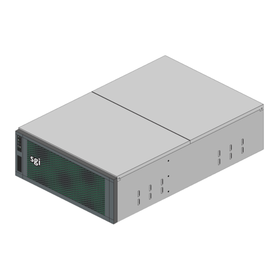
Page 18: System Overview
1: Introduction s g i Figure 1-1 SGI Modular InfiniteStorage NAS Enclosure Example System Overview The SGI Modular IS network-attached storage (NAS) is a file-level compute data storage connected to a computer network providing data access to a heterogeneous group of clients. The MIS NAS system not only operates as a file server but is specialized for this task by its hardware, software, and configurations of those elements. - Page 19 System Overview The SGI Modular InfiniteStorage NAS system is a high-density, integrated storage server platform. The MIS NAS always uses a 4U rackmount system, and can be either a compute and storage server, or a “Just Bunch Of Disks” expansion storage unit (MIS NAS JBOD unit). The MIS NAS Server Platform and up to 4 MIS NAS JBOD enclosures can be mounted into an SGI 42U (D-Rack).
-
Page 20: Next Steps
1: Introduction Caution: Floor loading has a maximum weight allowance of 250 lbs per square foot, not including the service area. Floor loading must be less than 250 lbs per square foot, including the service area. For maximum efficiency and performance, it is recommended that the maximum number of enclosures in a single D-Rack is one MIS NAS enclosure with 4 JBODs. -
Page 21: Mis Nas System Hardware Installation
Chapter 2 MIS NAS System Hardware Installation This chapter provides a hardware setup checklist and instructions to help you get the Modular IS NAS operational. If the MIS NAS hardware is already installed in a rack and cabled together as a system, continue on to Chapter 3, “MIS NAS Operation and GUI Startup,”... -
Page 22: Prepare For Setup
2: MIS NAS System Hardware Installation 2. Record any issues/problems (if applicable): • Use the bill of lading to record any issues discovered during the inspection. • Sign for the shipment after making notes on the bill of lading. 3. Report the issues to SGI: Contact the SGI Customer Support Center (CSC) at 1-800-800-4744 (in the United States;... -
Page 23: General Enclosure Precautions
Warnings and Precautions Warning: Extend the leveling jacks on the bottom of the rack to the floor with the full weight of the rack resting on them. Failure to do so can result in serious injury or death. Warning: Attach stabilizers to the rack in single rack installations. Failure to do so can result in serious injury or death. -
Page 24: Rack Mounting Considerations
2: MIS NAS System Hardware Installation Rack Mounting Considerations Ambient Operating Temperature If installed in a closed or multi-unit rack assembly, the ambient operating temperature of the rack environment may be greater than the ambient temperature of the room. Therefore, consideration should be given to installing the equipment in an environment compatible with the manufacturer’s maximum rated ambient temperature ( 35º... -
Page 25: Install The System Into A Rack
Install the System into a Rack Install the System into a Rack This section provides information on installing the Modular IS NAS into a rack. If the system has already been mounted into a rack, refer to the sections “Installing Drives in the MIS or JBOD Enclosure”... -
Page 26: Acclimatization
2: MIS NAS System Hardware Installation Acclimatization If the equipment has been in transit for more than 24 hours to reach the install site, wait 4 to 8 hours for the equipment to acclimate to the data center or lab environment before proceeding with the installation. -
Page 27: Installing Mis Platforms
Installing MIS Platforms Installing MIS Platforms After a shipment has been inspected (“Inspecting a Shipment” on page 5) and acclimated (“Acclimatization” on page 10) to the location, there are two scenarios for installing MIS NAS platforms (server and/or JBOD). One way is to install the platforms into a rack that is already on location (D-Rack or other supported rack systems). -
Page 28: Figure 2-1 D-Rack Stiffener Example
2: MIS NAS System Hardware Installation the sides of the rack. The brackets combine with a vertical 6x16 metric hex flange bolt to make the D-Rack Stiffener assembly. Note: Installation and use of the D-Rack Stiffener assembly is important because of the extremely heavy system weights that can occur with SGI MIS NAS configurations. -
Page 29: Installing The Rolling Rails
Installing the Rolling Rails Figure 2-2 Alignment with the D-Rack Stiffener Vertical Bolt Installing the Rolling Rails These instructions are for installing the rolling rails on chassis shipped separately (i.e., not in a rack). The rolling rails are used to support the chassis in the rack and provide ease of movement out the front and back of the rack, for easier and safer serviceability (see detail in Figure 2-3 on page 14). -
Page 30: Installing The Outer Rails
2: MIS NAS System Hardware Installation s g i Figure 2-3 Rolling Rails Example Installing the Outer Rails Hold up the outer rails to the rack to determine if the depth is correct. 2. If the rail cannot be secured to the rack at the front and rear, perform the following steps. Remove the four screws that hold the rear mounting plate to the rail. -
Page 31: Aligning The Outer Rails
Installing the Rolling Rails Note: If installing in a D-Rack with the D-Rack Stiffener (see Figure 2-1 on page 12), leave the vertical bolts loose. Then, using the small screws provided, attach the outer rail to the D-Rack Stiffener and secure the screws firmly. Make sure the screw heads are counter-sunk, so as not to catch on anything rolling in the rack. -
Page 32: Figure 2-4 Adjustment Using The Alignment Tool
2: MIS NAS System Hardware Installation alignment tool Figure 2-4 Adjustment Using the Alignment Tool 4. Tighten the screws on the right rail in order of front then back, leaving the middle bolts last (for D-Racks), so as to keep as straight an alignment as possible. 5. -
Page 33: Installing The Air Ducts
Installing the Rolling Rails Figure 2-5 Slide the Alignment Tool from Front to Back 6. When satisfied, remove the alignment tool from the rack. Installing the Air Ducts Place the left air duct above the left rail, see Figure 2-6 on page 18 for an example. -
Page 34: Figure 2-6 Air Duct Above Outer Rail
2: MIS NAS System Hardware Installation Figure 2-6 Air Duct Above Outer Rail 007-5921-001... -
Page 35: Installing The Inner Rolling Rails
Installing the Rolling Rails Installing the Inner Rolling Rails Align the rolling rails to the chassis so that the word “ FRONT ” is at the front of the chassis Note: The word “ ” will be upside-down on one side of the chassis, reference Figure 2-7. -
Page 36: Figure 2-8 Support Tabs
2: MIS NAS System Hardware Installation s g i Support tabs Support tabs Figure 2-8 Support Tabs 3. Slide the rolling rail beneath the support tabs on the side of the chassis until it locks firmly into place (see Figure 2-9 on page 21). -
Page 37: Figure 2-9 Lock On To Support Tabs
Installing the Rolling Rails s g i Figure 2-9 Lock on to Support Tabs 4. Using the included screws, attach the rolling rail to the chassis. Make sure the screw heads are counter-sunk, so as not to catch on anything when rolling in the rack. 5. -
Page 38: Install The Chassis Into The Rack
2: MIS NAS System Hardware Installation s g i Figure 2-10 Return Latch to Home Position Install the Chassis Into the Rack Using two people, line up the inner rails on the chassis with the outer rails in the rack. Slide the chassis into the rack. -
Page 39: Sliding The Chassis Forward/Backwards
Sliding the Chassis Forward/Backwards Sliding the Chassis Forward/Backwards To slide the chassis out in either direction, follow these steps: Push the two release latches in, at the left and right sides and in the center of the rail mounts, towards the center of the chassis. 2. -
Page 40: Figure 2-11 Chassis Cover Removal Example
2: MIS NAS System Hardware Installation s g i Remove screw s g i Figure 2-11 Chassis Cover Removal Example 007-5921-001... -
Page 41: Installing Drives In The Mis Or Jbod Enclosure
Installing Drives in the MIS or JBOD Enclosure Installing Drives in the MIS or JBOD Enclosure Drives are labeled with chassis, StorBrick, and drive information, reference Figure 2-12 and also Figure 2-13 on page 26. To install the drives, first slide the chassis forward (see “Sliding the Chassis Forward/Backwards”... -
Page 42: Figure 2-13 Example Storbrick Module With Drive In Carrier
2: MIS NAS System Hardware Installation Drives must first be installed in drive carriers before being installed into the StorBricks. To install a hard drive assembly into the StorBrick, perform the following steps: Figure 2-13 Example StorBrick Module with Drive in Carrier Locate the drives for StorBricks 0-4 and order them on a cart according to the labels on the drive carriers. -
Page 43: Check, Adjust Or Install Nas Cables
Check, Adjust or Install NAS Cables 5. When all drives are in their correct slots, replace the top cover on the chassis and secure it with its safety screw. 6. Move the chassis to the stowed position in the rack. 7. -
Page 44: Cable Guide & Chassis Location
2: MIS NAS System Hardware Installation Procedures to check already installed cabling are listed in “Check all Cable Connections and Airflow”. If your MIS NAS system is being installed on-site, install the needed cables as directed in the following subsections. Cable Guide &... -
Page 45: Figure 2-16 Cable Guide - Single Server With Two Jbods
Cable Guide & Chassis Location JBOD 1 HD miniSAS IOIOI HD miniSAS IOIOI NAS HEAD JBOD 0 HD miniSAS IOIOI HD miniSAS IOIOI Figure 2-16 Cable Guide – Single Server with two JBODs 007-5921-001... -
Page 46: Figure 2-17 Cable Guide - Single Server With Three Jbods
2: MIS NAS System Hardware Installation JBOD 1 HD miniSAS IOIOI HD miniSAS IOIOI NAS HEAD JBOD 0 HD miniSAS IOIOI HD miniSAS IOIOI JBOD 2 HD miniSAS IOIOI HD miniSAS IOIOI Figure 2-17 Cable Guide – Single Server With Three JBODs 007-5921-001... -
Page 47: Figure 2-18 Cable Guide - Single Server With Four Jbods
Cable Guide & Chassis Location JBOD 3 HD miniSAS IOIOI HD miniSAS IOIOI JBOD 1 HD miniSAS IOIOI HD miniSAS IOIOI NAS HEAD JBOD 0 HD miniSAS IOIOI HD miniSAS IOIOI JBOD 2 HD miniSAS IOIOI HD miniSAS IOIOI Figure 2-18 Cable Guide –... -
Page 48: Check All Cable Connections And Airflow
2: MIS NAS System Hardware Installation Check all Cable Connections and Airflow Make sure all power and data cables are properly connected and not blocking the system airflow. Check the Airflow The system component layout was carefully designed to direct sufficient cooling airflow to the components that generate the most heat. -
Page 49: Mis Nas Operation And Gui Startup
Chapter 3 MIS NAS Operation and GUI Startup Overview This chapter covers basic hardware operation and GUI startup for your MIS NAS system. Front Bezel and Control Panels On the chassis, next to the bezel grille, you can see a control panel (reference Figure 3-1). There is a control panel for each MIS NAS head server board in an SGI MIS NAS enclosure. -
Page 50: Figure 3-2 Mis Nas Control Panel Buttons, Icons And Leds
3: MIS NAS Operation and GUI Startup If the system is off, push this button to power on the system. If the operating system Power button is running, push this button to shut down the operating system and power down gracefully. Power LED Power button Status LED... -
Page 51: Mis Jbod Control Panel
Overview When lit, AC power is available to the power supply modules, whether or not the unit Status LED is on or off. When green, the system is in good working order. When yellow, a problem exists and service is required. When pushed, this service reset button reboots the server. -
Page 52: Safe Power-Off
3: MIS NAS Operation and GUI Startup Server. Since there is no boot drive module in a JBOD, the Boot Drive Activity LED, located next to the Network Activity LED, is present, but inactive. Important: When there are two I/O modules on a JBOD, the top control panel connects to the bottom I/O module on the back of the unit while the bottom control panel accesses the top I/O module. -
Page 53: Modular Infinitestorage (Mis) Nas Gui Startup
Modular InfiniteStorage (MIS) NAS GUI Startup USB ports Power supplies Video port NIC ports Figure 3-3 Single MIS NAS Head Node Rear Interface Components Example Modular InfiniteStorage (MIS) NAS GUI Startup The SGI MIS NAS is a software based network attached storage (NAS) appliance that features unlimited snapshots, snapshot mirroring (replication), NFS v3/v4, CIFS, and easy management of extremely large storage pools. -
Page 54: Obtain A Permanent Software License Key
3: MIS NAS Operation and GUI Startup Obtain a Permanent Software License Key To obtain your permanent software license key for each system running the SGI MIS NAS ™ software, open an SGI Supportfolio case using the following webpage: https://support.sgi.com/caseview/CreateNewCase In North America you may also obtain a key by calling 1.800.800.4744. -
Page 55: Registering The Sgi Mis Nas Software
Modular InfiniteStorage (MIS) NAS GUI Startup Registering the SGI MIS NAS Software Boot the SGI MIS NAS appliance. After the appliance boots up, review and accept the SGI MIS NAS software license agreement. You can display licensing information in NAS Management View (NMV) by selecting the 'About' link or use the following NAS Management Console (NMC) command: nmc:/$ show appliance license This will indicate whether you are using the trial or commercial edition, and how many days are... -
Page 56: Figure 3-5 Nas Software License Agreement Screen Example
3: MIS NAS Operation and GUI Startup For successful appliance registration, you need to provide a machine “signature”, a unique 9-character code that identifies your machine at the Software License registration page. Figure 3-5 shows an example Software License Agreement Screen, also known as an end-user license agreement (EULA). -
Page 57: Configure The Primary Network Interface
Modular InfiniteStorage (MIS) NAS GUI Startup Figure 3-6 Appliance Product Registration Screen Example Configure the Primary Network Interface To reconfigure the primary network interface, log in to the system console and execute the setup appliance init command: nmc: /$ setup appliance init Next, you will be prompted to reconfigure the primary network interface. -
Page 58: Choosing Sgi Nas Web Gui Transport Protocols
3: MIS NAS Operation and GUI Startup After you have reconfigured the Primary Network Interface, you should see an “Enabling message” on the screen similar to: Enabling ae0 via DHCP...OK. After choosing your primary IP settings, you need to select no to the reconfigure prompt at the bottom of the interface screen, see Figure 3-7. -
Page 59: Figure 3-8 Web Gui Protocol And Port Selection Screen Example
Modular InfiniteStorage (MIS) NAS GUI Startup Figure 3-8 WEB GUI Protocol and Port Selection Screen Example Note: During the process of network configuring you can specify the WEB GUI port. The default is 2000, but you can change it to 2001, 2002 or other ports if they are not being used by other services. -
Page 60: Finishing Initial Configuration
3: MIS NAS Operation and GUI Startup Figure 3-9 Initial Configuration Wizard URL Access Screen Example You will notice a brief instruction set displayed on the console above the login prompt. It is essential to follow these instructions and use the internet browser to perform a few basic configuration steps. -
Page 61: Preconfigured Storage Pool (Volume)
Modular InfiniteStorage (MIS) NAS GUI Startup Tip: If your internet browser does not connect to the appliance, it is likely because the primary networking interface is misconfigured. Recheck the procedures you executed in the previous two subsections. You may be able to fix the configuration by logging in to the console and running the following command: nmc:/$ setup appliance init Preconfigured Storage Pool (Volume) -
Page 63: System Safety
Chapter 4 System Safety This chapter describes basic safety precautions for working with the SGI Modular InfiniteStorage NAS systems. Electrical Safety Precautions Basic electrical safety precautions should be followed to protect yourself from harm and the Modular InfiniteStorage system from damage, as follows: •... -
Page 64: Mis Nas Node Serverboard Battery
4: System Safety MIS NAS Node Serverboard Battery Caution: There is a danger of explosion if the onboard battery is installed upside down, which will reverse its polarities (see Figure 4-1). This battery must be replaced only with the same or an equivalent type recommended by the manufacturer. Check with your service representative if you have any questions. -
Page 65: Esd Precautions
ESD Precautions When lifting the system, two people at either end should lift slowly with their feet spread out to distribute the weight. Always keep your back straight and lift with your legs. • Place the chassis top cover and any system components that have been removed away from the system or on a table so that they won't accidentally be stepped on. - Page 66 4: System Safety • For grounding purposes, make sure your computer chassis provides excellent conductivity between the power supply, the case, the mounting fasteners and the serverboard. 007-5921-001...
-
Page 67: Troubleshooting Information
Chapter 5 Troubleshooting Information This chapter includes basic troubleshooting information and best practice procedures to work with an SGI Modular InfiniteStorage NAS system. This chapter covers the following troubleshooting topics: • Detecting Component Failures • No Video • Loss of System Setup Configuration •... -
Page 68: Handling Nas Internal Components
5: Troubleshooting Information Handling NAS Internal Components Caution: Electrostatic discharge (ESD) can damage electrostatic-sensitive devices inside the NAS enclosure. Use the ESD precautions described below when you handle printed circuit boards or other components in the system. The following measures are generally sufficient: •... -
Page 69: Power Supply Leds
Handling NAS Internal Components Table 5-1 describes the meaning of the disk drive LEDs. Table 5-1 Disk Drive LEDs Bi-color LED Blue LED Drive Status Drive is off and can be removed. Green Drive is on. Yellow Service required. Off/Green/Yellow Indicates drive location. -
Page 70: No Video After Power-On
5: Troubleshooting Information Table 5-2 Power Supply LED Status Indicators (continued) Green LED Bi-color LED Power Supply Status Blinking Yellow AC available, power supply in standby mode (powered off on the front) Green AC available to the power supply, power supply is on and functioning normally. -
Page 71: Checking System Airflow
Handling NAS Internal Components • When logged in to the BMC and using the power control page to power off the sever. • Using the remote console screen GUI power-off button, if a KVM RMM4Lite session is established through the BMC. For an MIS NAS JBOD Unit, the power button on the front panel will turn off the power to that I/O module. -
Page 73: Bios Error Codes
Appendix A BIOS Error Codes During Power-On Self-Test (POST) routines, which are performed each time the system is powered on, errors may occur. Non-fatal errors are those which, in most cases, allow the system to continue the boot-up process. The error messages normally appear on the screen. The BMC may generate beep codes upon detection of failure conditions that do not allow the system to fully boot. -
Page 75: System Specifications And Regulatory Overview
Appendix B System Specifications and Regulatory Overview This appendix provides basic environmental operating requirements and regulatory information for the MIS NAS server. Operating Environment Table B-1 describes the technical specifications for the SGI MIS platform. Table B-1 Technical Specifications Attribute Specification Overview Profile... - Page 76 B: System Specifications and Regulatory Overview Table B-1 Technical Specifications (continued) Attribute Specification Safety –UL/CSA certified to UL6050-1 –CE/CB certified to EN60950/IEC60950 –North America FCC Class A –Europe EN55022/EN55024 Operating Environment º º º º Operating –41 to 95 F (5 to 35 temperature –processor cores automatically allowed to run faster than the base...
-
Page 77: Regulatory Compliance
Regulatory Compliance Table B-1 Technical Specifications (continued) Attribute Specification Internal storage Up to 72 SAS 2.5" or 3.5" drives (70 data drives) Two drives are reserved as boot disks in the controller enclosure SGI MIS NAS JBOD Specifications Internal Storage Up to 81 SAS 2.5"...
Need help?
Do you have a question about the NAS MIS and is the answer not in the manual?
Questions and answers