Table of Contents
Advertisement
Advertisement
Table of Contents

Related Manuals for Supermicro X13SWA-TF


Summary of Contents for Supermicro X13SWA-TF
- Page 1 X13SWA-TF USER'S MANUAL Revision 1.0...
- Page 2 State of California, USA. The State of California, County of Santa Clara shall be the exclusive venue for the resolution of any such disputes. Supermicro's total liability for all claims will not exceed the price paid for the hardware product.
- Page 3 Socket E1 LGA4677, with up to 56 CPU cores and a thermal design power (TDP) of up to 350W. Built with the Intel W790 chipset, the X13SWA-TF supports up to 1TB of ECC RDIMM and 4TB of 3DS RDIMM with speeds of up to 4800 MT/s (1DPC)/4400 MT/s (2DPC) in 16 ECC DDR5 (288-pin) SMD DIMM slots (for Intel Xeon W-3400 series processors).
- Page 4 Super X13SWA-TF User's Manual Contacting Supermicro Headquarters Address: Super Micro Computer, Inc. 980 Rock Ave. San Jose, CA 95131 U.S.A. Tel: +1 (408) 503-8000 Fax: +1 (408) 503-8008 Email: marketing@supermicro.com (General Information) Sales-USA@supermicro.com (Sales Inquiries) Government_Sales-USA@supermicro.com (Gov. Sales Inquiries) support@supermicro.com (Technical Support) RMA@supermicro.com (RMA Support)
-
Page 5: Table Of Contents
Preface Table of Contents Chapter 1 Introduction 1.1 Checklist ..........................7 1.2 Processor and Chipset Overview ..................18 1.3 Special Features ........................18 1.4 System Health Monitoring ....................18 1.5 ACPI Features ........................19 1.6 Power Supply ........................20 1.7 Serial Port ...........................20 Chapter 2 Installation 2.1 Static-Sensitive Devices .....................21 2.2 Processor and Heatsink Installation ..................22 2.3 Motherboard Installation .....................32... - Page 6 Super X13SWA-TF User's Manual 4.7 Boot ..........................138 4.8 Save & Exit ........................140 Appendix A BIOS POST Codes A.1 BIOS POST Codes ......................142 Appendix B Software B.1 Microsoft Windows OS Installation ...................143 B.2 Driver Installation ......................145 B.3 SuperDoctor 5 .........................146 ®...
-
Page 7: Chapter 1 Introduction
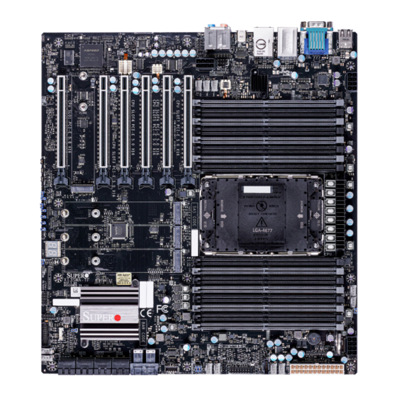
Introduction Congratulations on purchasing your computer motherboard from an industry leader. Supermicro motherboards are designed to provide you with the highest standards in quality and performance. In addition to the motherboard, several important parts that are included in the retail box are listed below. - Page 8 Super X13SWA-TF User's Manual Figure 1-1. X13SWA-TF Motherboard Image Note: All graphics shown in this manual were based upon the latest PCB revision available at the time of publication of the manual. The motherboard you received may or may not look exactly the same as the graphics shown in this manual.
- Page 9 Chapter 1: Introduction Figure 1-2. X13SWA-TF Motherboard Layout (not drawn to scale) LAN2 LAN1 HD AUDIO USB10 USB6/7 USB8/9 COM1 USB2/3 JUIDB1 (USB3.2 Gen 2X2) (USB3.2 Gen 2x1) (USB3.2 Gen 2x1) LED4 (UID-LED) JPAC1 JSPDIF_OUT AUDIO FP JPL2 BMC LED...
- Page 10 Super X13SWA-TF User's Manual Quick Reference (for Intel Xeon W-3400 Series CPU / 112L) JUIDB1 LAN2 USB6/7 JPAC1 AUDIO FP HD AUDIO LAN1 COM1 JSPDIF_OUT LED4 USB10 USB8/9 USB2/3 LAN2 LAN1 HD AUDIO USB10 USB6/7 USB8/9 COM1 USB2/3 JUIDB1 (USB3.2 Gen 2X2) (USB3.2 Gen 2x1)
- Page 11 LED7 (M.2-C04 LED) M.2-C03 LED6 LED5 M.2-C02 LED8 LED8 DIMME2 JBT1 DIMME1 DIMMF2 JBT1 M.2-C01 DIMMF1 LED3 BIOS LICENSE BIOS LICENSE X13SWA-TF JRK1 DIMME2 FAN5 REV:1.01 DIMME1 DESIGNED IN USA DIMMF2 DIMMF1 JTPM1 12V_PUMP_PWR1 MAC CODE USB0/1 USB0/1 DIMMG2 DIMMG1 DIMMH2...
- Page 12 Super X13SWA-TF User's Manual Quick Reference Table Jumper Description Default Setting JBT1 Clear CMOS (Onboard) Short Pads to Clear CMOS JPAC1 HD Audio Enable/Disable Pins 1-2 (Enabled) JPL1, JPL2 LAN1/LAN2 Enable/Disable Pins 1-2 (Enabled) JPME2 Intel Manufacturing Mode Pins 1-2 (Normal)
- Page 13 Front Access USB 3.2 Gen. 2x2 Header (20Gb, Type-C) VGA Port (IPMI only) Note: For detailed instructions on how to configure VROC RAID settings, please refer to the VROC RAID Configuration User's Guide posted on the web page under the link: https://www.supermicro.com/support/manuals/.
- Page 14 Super X13SWA-TF User's Manual Motherboard Features Motherboard Features • Supports a single Intel Xeon W-3400 (112L) / W-2400 (64L) series processor in Socket E1 LGA4677, with up to 56 cores and a thermal design power (TDP) of up to 350W Memory •...
- Page 15 Chapter 1: Introduction I/O Devices • • Serial (COM) Port One serial port on the rear I/O panel (COM1) • • SATA 3.0 Eight SATA 3.0 ports at 6 Gb/s (SATA0 – 7) • • Two U.2 connectors for NVMe 2.5" SSD drives (U.2-1, U.2-2) •...
- Page 16 For proper thermal management, please check the chas- sis and heatsink specifications. Note 2: For IPMI configuration instructions, please refer to the Embedded IPMI Con- figuration User's Guide available at https://www.supermicro.com/support/manuals/. Note 3: For proper BMC configuration, please refer to https://www.supermicro.com/...
- Page 17 Chapter 1: Introduction Figure 1-3. System Block Diagram SVID VR14s PCIE_PE5 PCIe x16 SLOT #1 (112L only) PCIE_PE1 PCIe x16 SLOT #3 DIMMA1 DIMMA2 PCIE_PE6 PCIe x16 SLOT #4 (112L only) DIMMB1 DIMMB2 PCIE_PE2 PCIe x16 SLOT #5 DIMMC1 DIMMC2 112L only PCIE_PE4 PCIe x16 SLOT #6...
-
Page 18: Processor And Chipset Overview
1.2 Processor and Chipset Overview Built upon the functionality and capability of the Intel Xeon processors (Socket E1) and the Intel W790 chipset, the X13SWA-TF motherboard increases energy efficiency, and system performance for a multitude of applications such as media and entertainment, engineering, scientific computing, and AI development applications. -
Page 19: Acpi Features
Plug and Play, and an operating system-independent interface for configuration control. ACPI leverages the Plug and Play BIOS data structures, while providing a processor architecture-independent implementation that is compatible with appropriate Windows operating systems. For detailed information regarding OS support, please refer to the Supermicro website. -
Page 20: Power Supply
It is even more important for processors that have high CPU clock rates where noisy power transmission is present. The X13SWA-TF motherboard accommodates a 24-pin ATX power connector. Although most power supplies generally meet the specifications required by the CPU, some are inadequate. -
Page 21: Chapter 2 Installation
Chapter 2: Installation Chapter 2 Installation 2.1 Static-Sensitive Devices Electrostatic Discharge (ESD) can damage electronic components. To avoid damaging your motherboard, it is important to handle them very carefully. The following measures are generally sufficient to protect your equipment from ESD. Precautions •... -
Page 22: Processor And Heatsink Installation
(112L, XCC) (64L, MCC) Note: The X13SWA-TF supports two CPU SKUs. Each SKU comes with a specific die and must use a specific carrier. The Intel Xeon W-3400 series processors come with Extreme Core Count (XCC) die and must use the CPU carrier E1A; the Intel Xeon W-2400 series processors come with High/Medium Core Count (MCC) die and must use the CPU carrier E1B. - Page 23 Chapter 2: Installation Overview of the Processor Carrier Assembly The processor carrier assembly includes a processor and a carrier as shown below: 1. Intel Xeon Processor Intel Xeon W-3400 series CPU Intel Xeon W-2400 series CPU (112L, XCC) (64L, MCC) 2.
- Page 24 Super X13SWA-TF User's Manual Overview of the CPU Socket The CPU socket is protected by a plastic protective cover. 1. Plastic Protective Cover 2. CPU Socket...
- Page 25 Chapter 2: Installation Overview of the Processor Heatsink Module The Processor Heatsink Module (PHM) contains a heatsink, a processor carrier, and the Intel Xeon processor. 1. Heatsink with Thermal Grease 2. Processor Carrier 3. Intel Xeon Processor Processor Heatsink Module (PHM) Bottom View...
- Page 26 Super X13SWA-TF User's Manual Creating the Processor Carrier Assembly To install a processor into the processor carrier, follow the steps below: 1. Before installation, make sure the lever on the processor carrier is pressed down as shown below. 2. Hold the processor with the LGA lands (gold contacts) facing up. Locate the small, gold triangle in the corner of the processor and the corresponding hollowed triangle on the processor carrier.
- Page 27 Chapter 2: Installation Assembling the Processor Processor Carrier Assembly Heatsink Module (Upside Down) After creating the processor carrier assembly for the processor, mount it Triangle on the CPU onto the heatsink to create the processor heatsink module (PHM): 1. Note the label on top of the Thermal heatsink, which marks the airflow grease...
- Page 28 Super X13SWA-TF User's Manual Preparing the CPU Socket for Installation This motherboard comes with a plastic protective cover installed on the CPU socket. Remove it from the socket to install the Processor Heatsink Module (PHM). Gently pull up one corner of the plastic protective cover to remove it.
- Page 29 Chapter 2: Installation Installing the Processor Heatsink Module After assembling the Processor Heatsink Module (PHM), install it onto the CPU socket: 1. Align pin 1 of the PHM with the printed triangle on the CPU socket. See the left image below.
- Page 30 Super X13SWA-TF User's Manual 6. Connect the fan power connector to a 4-pin fan header on the motherboard.
- Page 31 Chapter 2: Installation Removing the Processor Heatsink Module Before removing the processor heatsink module (PHM) from the motherboard, shut down the system and then unplug the AC power cord from all power supplies. Then follow the steps below: 1. Unplug the fan power connector from the fan header.
-
Page 32: Motherboard Installation
Super X13SWA-TF User's Manual 2.3 Motherboard Installation All motherboards have standard mounting holes to fit different types of chassis. Make sure that the locations of all the mounting holes for both the motherboard and the chassis match. Although a chassis may have both plastic and metal mounting fasteners, metal ones are highly recommended because they ground the motherboard to the chassis. - Page 33 Chapter 2: Installation Installing the Motherboard 1. Install the I/O shield into the back of the chassis, if applicable. 2. Locate the mounting holes on the motherboard. See the previous page for the location. 3. Locate the matching mounting holes on the chassis. Align the mounting holes on the motherboard against the mounting holes on the chassis.
-
Page 34: Memory Support And Installation
Super X13SWA-TF User's Manual 2.4 Memory Support and Installation Note: Check the Supermicro website for recommended memory modules. Important: Exercise extreme care when installing or removing DIMM modules to pre- vent any possible damage. Memory Support For Intel Xeon W-3400 series processors (112L): support up to 1TB of ECC RDIMM and 4TB of 3DS RDIMM with speeds of up to 4800 MT/s (1DPC) and 4400 MT/s (2DPC) in 16 ECC DDR5 (288-pin) SMD DIMM slots. - Page 35 Chapter 2: Installation DDR5 Memory Population Tables DDR5 Memory Population Table for Intel Xeon W-3400 Series Processors (112L) (16 DIMM Slots) DDR5 DIMMH1 DIMMH2 DIMMG1 DIMMG2 DIMMF1 DIMMF2 DIMME1 DIMME2 DIMMA2 DIMMA1 DIMMB2 DIMMB1 DIMMC2 DIMMC1 DIMMD2 DIMMD1 DDR5 DDR5 DDR5 DDR5 DDR5...
- Page 36 Super X13SWA-TF User's Manual General Guidelines for Optimizing Memory Performance • It is recommended to use DDR5 memory of the same type, size, and speed. • Mixed DIMM speeds can be installed. However, all DIMMs will run at the speed of the slowest DIMM.
- Page 37 1. Insert the desired number of DIMMs into the memory slots based on the recommended DIMM population tables in the previous section. Locate DIMM memory slots on the X13SWA-TF X13SWA-TF REV:1.01 REV:1.01 DESIGNED IN USA DESIGNED IN USA motherboard as shown on the left.
-
Page 38: Installation
DESIGNED IN USA Note 1: Please use wide temperature (up to 85°C) M.2 devices for M.2-C4 and M.2-C3. Note 2: It is strongly recommended that you install an optional Supermicro M.2 heatsink (p/n SNK-C0156L) on the M.2 device. M.2 Heatsink Installation (Optional) 1. - Page 39 3. Insert the M.2 device or the heatsink assembly into the M.2 socket at a 30-degree angle and press it down. Standard M.2 device M.2 device with Supermicro heatsink 4. Tighten the standoff screw to secure the M.2 device or the heatsink assembly into place. Do not overtighten so as to avoid damaging the M.2 device.
- Page 40 Super X13SWA-TF User's Manual 22110 M.2 Device Installation 1. Locate the pre-installed standoff. Remove the standoff screw and set it aside. 2. Insert the M.2 device or the heatsink assembly into the M.2 socket at a 30-degree angle and press it down.
-
Page 41: Rear I/O Ports
DIMMD1 DIMMD2 DIMMC1 DIMMC2 DIMMB1 DIMMB2 DIMMA1 DIMMA2 M.2-C04 (PCIe 5.0 X4) LED7 (M.2-C04 LED) LED8 JBT1 BIOS LICENSE BIOS LICENSE X13SWA-TF DIMME2 REV:1.01 DIMME1 DESIGNED IN USA DIMMF2 DIMMF1 MAC CODE USB0/1 DIMMG2 DIMMG1 DIMMH2 DIMMH1 U.2-2 U.2-1 JPI2C1... - Page 42 Super X13SWA-TF User's Manual Back Panel High Definition Audio (HD Audio) This motherboard features a 7.1+2 Channel High Definition Audio (HDA) codec that provides 10 DAC channels. The HD Audio connections simultaneously support multiple-streaming 7.1 sound playback with 2 channels of independent stereo output through the front panel stereo out for front, rear, center, and subwoofer speakers.
- Page 43 DIMMD1 DIMMD2 DIMMC1 DIMMC2 DIMMB1 DIMMB2 DIMMA1 DIMMA2 M.2-C04 (PCIe 5.0 X4) LED7 (M.2-C04 LED) LED8 JBT1 BIOS LICENSE BIOS LICENSE X13SWA-TF DIMME2 REV:1.01 DIMME1 DESIGNED IN USA DIMMF2 DIMMF1 MAC CODE DIMMG2 USB0/1 DIMMG1 DIMMH2 DIMMH1 U.2-2 U.2-1 JPI2C1...
- Page 44 Super X13SWA-TF User's Manual LAN Ports Two LAN ports (LAN1 and LAN2) are located on the rear I/O panel. LAN1 supports 1GbE LAN connection and shares with the IPMI port (via the Intel i210AT LAN controller). LAN2 supports 10GbE LAN connection (via the Aquantia AQC113C LAN controller). All of these LAN ports accept RJ45 cables.
- Page 45 DIMMB2 DIMMA1 6. Rear I/O Panel USB10 DIMMA2 M.2-C04 (PCIe 5.0 X4) 7. Front Access USB11 LED7 (M.2-C04 LED) LED8 JBT1 BIOS LICENSE BIOS LICENSE X13SWA-TF DIMME2 REV:1.01 DIMME1 DESIGNED IN USA DIMMF2 DIMMF1 MAC CODE USB0/1 DIMMG2 DIMMG1 DIMMH2 DIMMH1 U.2-2...
- Page 46 Super X13SWA-TF User's Manual UID (Unit Identifier)/BMC Reset Switch and UID/BMC Reset LED Indicators A UID / BMC Reset switch (JUIDB1) is located on the rear side of the motherboard. This switch has dual functions. It can be used to identify a system unit that is in need of service, and it can also be used to reset the BMC settings.
- Page 47 1. UID Switch / BMC Reset (JUIDB1) LED7 (M.2-C04 LED) 2. Rear UID LED (LED4) LED8 3. Front UID LED JBT1 4. BMC Heartbeat LED (BMC LED) BIOS LICENSE BIOS LICENSE X13SWA-TF DIMME2 REV:1.01 DIMME1 DESIGNED IN USA DIMMF2 DIMMF1 MAC CODE USB0/1...
-
Page 48: Front Control Panel
These connectors are designed specifically for use with Supermicro chassis. Refer to the figure below for the descriptions of the front control panel buttons and LED indicators. - Page 49 Chapter 2: Installation Front Control Panel LEDs Power Button Ground Reset Button Ground Power Fail (for LED6) 3.3V Red+ Blue+ (Blue LED_Cathode_UID) (Red OH/Fan Fail/PWR Fail for LED5/Blue UID LED) P3V3_STBY NIC2 Active LED NIC1 Active LED P3V3_STBY ID_UID/3.3V Stby HDD LED FP PWR LED 3.3V...
- Page 50 Super X13SWA-TF User's Manual Power On & BMC/BIOS Status LED Button The Power On and BMC/BIOS Status LED button is located on pins 1 and 2 of JF1. Momentarily contacting both pins will power on/off the system or display BMC/BIOS status.
- Page 51 Chapter 2: Installation Power Fail LED The Power Fail LED connection is located on pins 5 and 6 of JF1. When this LED turns solid red, it indicates a power failure. Refer to the table below for pin definitions. Power Fail LED Pin Definitions (JF1) Pin# Definition...
- Page 52 Super X13SWA-TF User's Manual NIC1/NIC2 (LAN1/LAN2) The Network Interface Controller (NIC) LED connection for LAN port 1 is located on pins 11 and 12 of JF1, and LAN port 2 is on pins 9 and 10. Attach the NIC LED cables here to display network activity.
- Page 53 Chapter 2: Installation FP Power LED The Front Panel Power LED connection is located on pins 15 and 16 of JF1. Refer to the table below for pin definitions. FP Power LED Pin Definitions (JF1) Pins Definition 3.3V FP PWR LED NMI Button The non-maskable interrupt (NMI) button header is located on pins 19 and 20 of JF1.
-
Page 54: Connectors
Super X13SWA-TF User's Manual 2.8 Connectors Power Connections ATX Power Supply Connector The 24-pin power supply connector (JPW1) meets the ATX SSI EPS 12V specification. If required, you also need to connect the 8-pin 12V DC power connectors (JPW2/JPW3/JPW4) to the power supply to provide adequate power to your system. - Page 55 Chapter 2: Installation (Continued from previous page) Important: To provide adequate power supply to the motherboard, be sure to connect the 24-pin ATX power connector and the required 8-pin power connectors to the power supply. Failure to do so may void the manufacturer warranty on your power supply and motherboard.
- Page 56 Super X13SWA-TF User's Manual Headers Fan Headers There are ten 4-pin fan headers (FAN1 – FAN6 and FANA – FAND) on the motherboard. All these 4-pin fan headers are backwards compatible with the traditional 3-pin fans. However, fan speed control is available for 4-pin fans only by Thermal Management via the IPMI 2.0 interface.
- Page 57 DIMMD1 DIMMD2 DIMMC1 DIMMC2 DIMMB1 DIMMB2 DIMMA1 DIMMA2 M.2-C04 (PCIe 5.0 X4) LED7 (M.2-C04 LED) LED8 JBT1 BIOS LICENSE BIOS LICENSE X13SWA-TF DIMME2 REV:1.01 DIMME1 DESIGNED IN USA DIMMF2 DIMMF1 MAC CODE USB0/1 DIMMG2 DIMMG1 DIMMH2 DIMMH1 U.2-2 U.2-1 JPI2C1...
- Page 58 Super X13SWA-TF User's Manual Speaker/Buzzer Header On the JD1 header, pins 1-4 are for the speaker and pins 3-4 are for the buzzer. If you wish to use an external speaker, connect its cable to pins 1-4. Speaker Connector Pin Definitions...
- Page 59 The JTPM1 header is used to connect a Trusted Platform Module (TPM)/Port 80, which is available from Supermicro (optional). A TPM/Port 80 header is a security device that supports encryption and authentication in hard drives. It allows the motherboard to deny access if the TPM associated with the hard drive is not installed in the system.
- Page 60 Super X13SWA-TF User's Manual VROC RAID Key Header A VROC RAID Key header is located at JRK1 on the motherboard. Install a VROC RAID Key on JRK1 for NVMe RAID support as shown in the illustration below. Refer to the layout below for the location of JRK1.
- Page 61 DIMMD1 DIMMD2 DIMMC1 DIMMC2 DIMMB1 DIMMB2 DIMMA1 DIMMA2 M.2-C04 (PCIe 5.0 X4) LED7 (M.2-C04 LED) LED8 JBT1 BIOS LICENSE BIOS LICENSE X13SWA-TF DIMME2 REV:1.01 DIMME1 DESIGNED IN USA DIMMF2 DIMMF1 MAC CODE USB0/1 DIMMG2 DIMMG1 DIMMH2 DIMMH1 U.2-2 U.2-1 JPI2C1...
- Page 62 Super X13SWA-TF User's Manual Chassis Intrusion A Chassis Intrusion header is located at JL1 on the motherboard. Attach the appropriate cable from the chassis to inform you when the chassis is opened. Refer to the table below for pin definitions.
- Page 63 4. M.2 Socket (M.2-C04) DIMMD2 DIMMC1 DIMMC2 DIMMB1 DIMMB2 DIMMA1 DIMMA2 M.2-C04 (PCIe 5.0 X4) LED7 (M.2-C04 LED) LED8 JBT1 BIOS LICENSE BIOS LICENSE X13SWA-TF DIMME2 REV:1.01 DIMME1 DESIGNED IN USA DIMMF2 DIMMF1 MAC CODE USB0/1 DIMMG2 DIMMG1 DIMMH2 DIMMH1 U.2-2 U.2-1...
- Page 64 Super X13SWA-TF User's Manual Overheat/Fan Fail LED Header Header JOH1 is used to connect to an LED indicator to provide warnings of chassis overheating and fan failure. This LED will blink when a fan failure occurs. Refer to the tables below for pin definitions.
- Page 65 DIMMC2 5. U.2-2 DIMMB1 DIMMB2 6. U.2-1 DIMMA1 DIMMA2 M.2-C04 (PCIe 5.0 X4) LED7 (M.2-C04 LED) LED8 JBT1 BIOS LICENSE BIOS LICENSE X13SWA-TF DIMME2 REV:1.01 DIMME1 DESIGNED IN USA DIMMF2 DIMMF1 MAC CODE USB0/1 DIMMG2 DIMMG1 DIMMH2 DIMMH1 U.2-2 U.2-1...
-
Page 66: Jumper Settings
Super X13SWA-TF User's Manual 2.9 Jumper Settings How Jumpers Work To modify the operation of the motherboard, jumpers can be Connector used to choose between optional settings. Jumpers create shorts Pins between two pins to change the function of the connector. Pin 1 is identified with a square solder pad on the printed circuit board. - Page 67 DIMMD1 DIMMD2 DIMMC1 DIMMC2 DIMMB1 DIMMB2 DIMMA1 DIMMA2 M.2-C04 (PCIe 5.0 X4) LED7 (M.2-C04 LED) LED8 JBT1 BIOS LICENSE BIOS LICENSE X13SWA-TF DIMME2 REV:1.01 DIMME1 DESIGNED IN USA DIMMF2 DIMMF1 MAC CODE DIMMG2 USB0/1 DIMMG1 DIMMH2 DIMMH1 U.2-2 U.2-1 JPI2C1...
- Page 68 Super X13SWA-TF User's Manual HD Audio Enable JPAC1 allows you to enable or disable the onboard high definition audio support. The default position is on pins 1-2 to enable onboard audio connections. Refer to the table below for jumper settings.
- Page 69 DIMMD1 DIMMD2 DIMMC1 DIMMC2 DIMMB1 DIMMB2 DIMMA1 DIMMA2 M.2-C04 (PCIe 5.0 X4) LED7 (M.2-C04 LED) LED8 JBT1 BIOS LICENSE BIOS LICENSE X13SWA-TF DIMME2 REV:1.01 DIMME1 DESIGNED IN USA DIMMF2 DIMMF1 MAC CODE USB0/1 DIMMG2 DIMMG1 DIMMH2 DIMMH1 U.2-2 U.2-1 JPI2C1...
-
Page 70: Led Indicators
Super X13SWA-TF User's Manual 2.10 LED Indicators LAN 1/LAN 2 LAN1/LAN2 LEDs The LED on the left indicates the speed of the connection, and the Link Activity LED on the right indicates activity. Refer to the tables below for more information. - Page 71 DIMMC1 5. LED7 (for M.2-C04) DIMMC2 DIMMB1 DIMMB2 DIMMA1 DIMMA2 M.2-C04 (PCIe 5.0 X4) LED7 (M.2-C04 LED) LED8 JBT1 BIOS LICENSE BIOS LICENSE X13SWA-TF DIMME2 REV:1.01 DIMME1 DESIGNED IN USA DIMMF2 DIMMF1 MAC CODE DIMMG2 USB0/1 DIMMG1 DIMMH2 DIMMH1 U.2-2 U.2-1...
- Page 72 Super X13SWA-TF User's Manual Status Code LED LED8 is an alphanumeric display with two LED digits to provide the status or POST code, when the motherboard is powered on. Please download the following AMI publication for a complete list of POST codes: https://www.supermicro.com/manuals/other/AMI_AptioV_BIOS_...
-
Page 73: Chapter 3 Troubleshooting
Chapter 3: Troubleshooting Chapter 3 Troubleshooting 3.1 Troubleshooting Procedures Use the following procedures to troubleshoot your system. If you have followed all of the procedures below and still need assistance, refer to the ‘Technical Support Procedures’ and/ or ‘Returning Merchandise for Service’ section(s) in this chapter. Always disconnect the AC power cord before adding, changing or installing any non hot-swap hardware components. - Page 74 Super X13SWA-TF User's Manual No Video 1. If the power is on, but you do not have video, remove all add-on cards and cables. 2. Remove all memory modules and turn on the system (if the alarm is on, check the specs of memory modules, reset the memory, or try a different one).
- Page 75 Chapter 3: Troubleshooting Losing the System's Setup Configuration 1. Make sure that you are using a high-quality power supply. A poor-quality power supply may cause the system to lose the CMOS setup information. Refer to Chapter 1 for details on recommended power supplies. 2.
-
Page 76: Technical Support Procedures
Before contacting Technical Support, please take the following steps. Also, please note that as a motherboard manufacturer, Supermicro also sells motherboards through its channels, so it is best to first check with your distributor or reseller for troubleshooting services. They should know of any possible problems with the specific system configuration that was sold to you. -
Page 77: Frequently Asked Questions
BIOS revision to make sure that it is newer than your BIOS before downloading. Note: The SPI BIOS chip used on this motherboard cannot be removed. Send your motherboard back to our RMA Department at Supermicro for repair. For BIOS Recov- ery instructions, please refer to the AMI BIOS Recovery Instructions posted at https:// www.supermicro.com/support/manuals/. -
Page 78: Battery Removal And Installation
Super X13SWA-TF User's Manual 4. The flash.nsh script will start the BIOS update process. 5. Perform an A/C power cycle after the message indicating the BIOS update has completed. 3.4 Battery Removal and Installation Battery Removal To remove the onboard battery, follow the steps below: 1. -
Page 79: Returning Merchandise For Service
For faster service, you can also request a RMA authorization online (https://www.supermicro. com/RmaForm/). This warranty only covers normal consumer use and does not cover damages incurred in shipping or from failure due to the alternation, misuse, abuse or improper maintenance of products. -
Page 80: Chapter 4 Uefi Bios
Super X13SWA-TF User's Manual Chapter 4 UEFI BIOS 4.1 Introduction This chapter describes the AMIBIOS™ Setup utility for the motherboard. The BIOS is stored on a chip and can be easily upgraded using a flash program. Note: Due to periodic changes to the BIOS, some settings may have been added or deleted and might not yet be recorded in this manual. -
Page 81: Main Setup
Note: The time is in the 24-hour format. For example, 5:30 P.M. appears as 17:30:00. The date's default value is the BIOS build date after the RTC (Real Time Clock) reset. Supermicro X13SWA-TF BIOS Version This feature displays the version of the BIOS ROM used in the system. -
Page 82: Advanced Setup Configurations
Super X13SWA-TF User's Manual 4.3 Advanced Setup Configurations Use the arrow keys to select the Advanced submenu and press <Enter> to access the submenu items: Warning: Take Caution when changing the Advanced settings. An incorrect value, an improper DRAM frequency, or a wrong BIOS timing setting may cause the system to malfunction. When this occurs, restore the setting to the manufacturer default setting. - Page 83 Supermicro Management Software and Utilities features. Contact us for more information. Note 2: Refer to submenu of Security -> Supermicro Security Erase Configuration to set "Lockdown Mode". Rear USB Port(s) (Available when "Lockdown Mode" is set to Enabled with the DCMS key) Select Enabled to allow the specific type of USB devices to be used in the rear USB ports.
- Page 84 Super X13SWA-TF User's Manual Restore on AC Power Loss Use this feature to set the power state after a power outage. Select Power Off for the system power to remain off after a power loss. Select Power On for the system power to be turned on after a power loss.
- Page 85 Chapter 4: UEFI BIOS Advanced Power Management Configuration Power Technology Select Energy Efficient to support power-saving mode. Select Custom to customize system power settings. Select Disabled to disable power-saving settings. The options are Disable, Energy Efficient, and Custom. Power Performance Tuning (Available when "Power Technology" is set to Custom) Set this feature to allow either operating system (OS) or the BIOS to control the EPB.
- Page 86 Super X13SWA-TF User's Manual ing SIMD Extensions (SSE) and AVX workloads. Each P1 ratio has the corresponding AVX Impressed Current Cathodic Protection (ICCP) pre-grant license level, which refers to the selection between different AVX ICCP transition levels. The options are Nominal, Level 1, and Level 2.
- Page 87 Chapter 4: UEFI BIOS CPU C6 Report Select Enable to allow the BIOS to report the CPU C6 State (ACPI C3) to the operating system. During the CPU C6 State, the power to all cache is turned off. The options are Disable, Enable, and Auto.
- Page 88 Super X13SWA-TF User's Manual PL1 Power Limit Use this feature to configure PL1 power limit. If the value is 0, the fused value will be pro- grammed. A value greater than fused TDP value will no be programmed. The default is 0.
- Page 89 Chapter 4: UEFI BIOS LLC Prefetch If this feature is set to Enable, LLC (hardware cache) prefetching on all threads will be supported. The options are Disable and Enable. Homeless Prefetch Use this feature to enable or disable homeless prefetch on all threads. If Auto is selected, it will map to haredware default settings.
- Page 90 Super X13SWA-TF User's Manual ---------------------------------------------------------------- TME, TME-MT, TDX ---------------------------------------------------------------- Memory Encryption (TME) Select Enabled for Intel Total Memory Encryption (TME) support to enhance memory data security. The options are Disabled and Enabled. Total Memory Encryption (TME) Bypass (Available when "Memory Encryption (TME)"...
- Page 91 Chapter 4: UEFI BIOS Chipset Configuration Warning: Setting the wrong values in the following features may cause the system to malfunc- tion. North Bridge This feature allows you to configure the following North Bridge settings. Uncore Configuration The following information is displayed. •...
- Page 92 Super X13SWA-TF User's Manual LLC Dead Line Alloc Select Enable to opportunistically fill the dead lines in the LLC. The options are Disable, Enable, and Auto. Memory Configuration This feature allows you to configure the Integrated Memory Controller (iMC) settings.
- Page 93 Chapter 4: UEFI BIOS Correctable Error Threshold Use this feature to specify the threshold value for correctable memory-error logging, which sets a limit on the maximum number of events that can be logged in the memory error log at a given time. The default setting is 512. ADDDC Sparing (Available when populating 1Rx4, 2Rx4, and 4Rx4 DIMM) Select Enabled for Adaptive Double Device Data Correction (ADDDC) support, which will not only provide memory error checking and correction but will also prevent the...
- Page 94 Super X13SWA-TF User's Manual IIO Configuration CPU Configuration IOU0 (IIO PCIe Port 1) / IOU1 (IIO PCIe Port 2) / IOU2 (IIO PCIe Port 3) / IOU3 (IIO PCIe Port 4) / IOU4 (IIO PCIe Port 5) / IOU5 (IIO PCIe Port 6) / IOU6 (IIO PCIe Port 7) This feature is CPU dependent.
- Page 95 Chapter 4: UEFI BIOS IOAT Configuration Relaxed Ordering Select Yes to allow certain transactions to be processed and completed before other transactions that have already been enqueued. The options are No and Yes. Intel VT for Directed I/O (VT-d) ...
- Page 96 Super X13SWA-TF User's Manual IIO eDPC Interrupt (Available when your system supports this feature and when "IIO eDPC Support" is set to On Fatal Error/On Fatal and Non-Fatal Errors) Select Enable to enable IIO eDPC Interrupt support. The options are Enable and Disable.
- Page 97 Chapter 4: UEFI BIOS Intel VMD for Volume Management Device on CPU VMD Config for PCH ports Enable/Disable VMD Select Enable to enable the Intel Volume Management Device (VMD) technology support for the root port specified. The options are Disable and Enable. U.2-1 VMD / U.2-2 VMD (Available when the device is detected by the system and "Enable/Disable VMD"...
- Page 98 Super X13SWA-TF User's Manual IIO-PCIe Express Global Options PCIe ASPM Support (Global) Use this feature to disable the Active State Power Management (ASPM) support for all PCIe root ports. The options are Disable and Auto. IIO eDPC Support Use this feature to configure the setting for IIO Enhanced Downstream Port Containment...
- Page 99 Chapter 4: UEFI BIOS Overclocking Feature (Available for CPU supporting overclocking) Overclocking Feature This feature enables the CPU overclocking. The options are Enabled and Disabled. *If the feature of Overclocking is set to Enabled, the following feature will become available for configuration: Processor VF Configuration Scope Use this feature to configure the VF curve.
- Page 100 Super X13SWA-TF User's Manual TjMax Override Enter a value for TjMax ratio override. The range is 105 – 115.The default is 0 (no override). Per Core Ratio Override This feature enables CPU per core ratio overriding. When enabled, it sets the maximum overclocking ratio to specific core by OCMB 0x1D command.
- Page 101 Chapter 4: UEFI BIOS Uncore Domain VCC Voltage Override This feature controls the Domain VCC voltage mode. The options are Disable and Override. *If the feature above is set to Override, the following features will be available: VCCCFN Voltage Override Use this feature to specify the override voltage applied to the VCCCFN domain (in mV).
- Page 102 Super X13SWA-TF User's Manual FIVR Faults Use this feature to enable or disable Fully-Integrated Voltage Regulators (FIVR) faults. When FIVR faults are disabled, OVP and OCP protection mechanisms will be masked. The options are Disabled and Enabled. Warning: There is a risk of disabling this setting and you shall be solely responsible for disabling this settings.
- Page 103 Chapter 4: UEFI BIOS PCH-FW Configuration The following firmware information will display: • ME Firmware Mode • ME Firmware SKU ME FW Image Re-Flash Use this feature to update the Management Engine firmware. The options are Enabled and Disabled. PTT Configuration PTT Capability / State This features displays the information of Intel Platform Trust Technology (PTT) capability and state.
- Page 104 Super X13SWA-TF User's Manual Support Aggressive Link Power Management (Available when "SATA Configuration" is set to Enabled) When this feature is set to Enabled, the SATA AHCI controller manages the power use of the SATA link. The controller will put the link in a low power mode during an extended period of I/O inactivity, and will return the link to an active state when I/O activity resumes.
- Page 105 Chapter 4: UEFI BIOS Security Device Support Select Enable to enable BIOS support for onboard security devices, which are not displayed in the OS. If this feature is set to Enable, TCG EFI protocol and INT1A interface will not be available.
- Page 106 The options are Disabled and Enabled. Supermicro BIOS-Based TPM Provision Support If this feature is set to Enabled, Supermicro BIOS-based TPM provision will be supported. The options are Disabled and Enabled. Note: Enabling this feature will lock your TPM on the production platform, and you will not be able to delete the NV indexes.
- Page 107 Chapter 4: UEFI BIOS OS environment to reduce system crashes and to enhance system recovery and health monitoring. The options are Disabled and Enabled. High Precision Event Timer Select Enabled to activate the High Precision Event Timer (HPET) that produces periodic interrupts at a much higher frequency than a Real-time Clock (RTC) does in synchronizing multimedia streams, providing smooth playback and reducing the dependency on other timestamp calculation devices, such as an x86 RDTSC Instruction embedded in the CPU.
- Page 108 Super X13SWA-TF User's Manual Console Redirection Settings (Available when "Console Redirection" above is set to Enabled) Terminal Type Use this feature to select the target terminal emulation type for Console Redirection. Select VT100 to use the ASCII Character set. Select VT100+ to add color and function key support.
- Page 109 Chapter 4: UEFI BIOS Recorder Mode Select Enabled to capture the data displayed on a terminal and send it as text messages to a remote server. The options are Disabled and Enabled. Resolution 100x31 Select Enabled for extended-terminal resolution support. The options are Disabled and Enabled.
- Page 110 Super X13SWA-TF User's Manual use UTF8 encoding to map Unicode characters into one or more bytes. The options are VT100, VT100+, VT-UTF8, and ANSI. Bits Per Second Use this feature to set the transmission speed for a serial port used in Console Redirection.
- Page 111 Chapter 4: UEFI BIOS Putty KeyPad This feature selects Function Keys and KeyPad settings for Putty, which is a terminal emulator designed for the Windows OS. The options are VT100, LINUX, XTERMR6, SCO, ESCN, and VT400. Legacy OS Redirection Resolution Use this feature to select the numbers of rows and columns used in Console Redirection for Legacy OS support.
- Page 112 Super X13SWA-TF User's Manual Bits Per Second EMS This feature sets the transmission speed for a serial port used in Console Redirection. Make sure that the same speed is used in the host computer and the client computer. A lower transmission speed may be required for long and busy lines. The options are 9600, 19200, 57600, and 115200 (bits per second).
- Page 113 Chapter 4: UEFI BIOS Media Detect Count Use this feature to select the wait time (in seconds) for the BIOS ROM to detect the presence of a LAN media either via the Internet connection or via a LAN port. Press "+" or "-" on your keyboard to change the value.
- Page 114 Super X13SWA-TF User's Manual Interface ID Use this feature to change/enter the 64-bit alternative interface ID for the device. The string format is colon separated. The default setting is the MAC address above. DAD Transmit Count This feature displays the number of consecutive neighbor solicitation messages have been sent while performing duplicate address detection on a tentative address.
- Page 115 Chapter 4: UEFI BIOS PCI Devices Common Settings: Above 4G Decoding (Available when the system supports 64-bit PCI decoding) Select Enabled to decode a PCI device that supports 64-bit in the space above 4G Address. The options are Disabled and Enabled. MMCFG Base This feature determines how the lowest Memory Mapped Configuration (MMCFG) base is assigned to onboard PCI devices.
- Page 116 Super X13SWA-TF User's Manual Onboard Video Option ROM Select EFI to allow you to boot the computer using the Extensible Firmware Interface (EFI) device installed on the onboard video port. The options are Disabled and EFI. CPU SLOT1 PCIe 5.0 X16 OPROM / CPU SLOT3 PCIe 5.0 X16 OPROM / CPU SLOT4 PCIe 5.0 X16 OPROM / CPU SLOT5 PCIe 5.0 X16 OPROM / CPU SLOT6 PCIe 5.0 X16...
- Page 117 Chapter 4: UEFI BIOS Boot URI Enter a Boot Uniform Research Identifier (URI) with 128 characters or shorter. This Boot URI determines how IPv4 Boot Option and IPv6 Boot Option will be created. This feature is only supported on Dual or EFI Boot Mode. Instance of Priority 2: / Instance of Priority 3: / Instance of Priority 4: / Instance of Priority 5: / Instance of Priority 6: / Instance of Priority 7: / Instance of Priority 8: (Available when your motherboard supports this feature)
- Page 118 Super X13SWA-TF User's Manual Select Disks: Select the desired RAID disks one by one by setting them to X. The options are (not selected) and X (selected). Strip Size: (Available for RAID0/RAID5/RAID10 Only) Use this feature to select the RAID strip size. The options are 4KB, 8KB, 16KB, 32KB, 64KB, and 128KB.
- Page 119 Chapter 4: UEFI BIOS 3. When asked to confirm deletion of the RAID volume, select Yes to delete the RAID volume. Note: When deleting a RAID volume, all data on the disks will be deleted as well. Rebuild (a RAID Volume) To rebuild a degraded RAID volume, take the steps below after replacing a failed hard drive: 1.
- Page 120 Super X13SWA-TF User's Manual 3. Select Reset. When asked to remove the RAID structure on the disk, select Yes to reset the disk. Note: When resetting a disk, all data on the disk will be deleted as well. Intel(R) I210 Gigabit Network Connection - (MAC address) Note: The Ethernet controller and MAC addresses shown above are based on you system features.
- Page 121 Chapter 4: UEFI BIOS PCI Virtual Functions Advertised This feature displays the base PCI virtual functions advertised. ISCSI Configuration iSCSI General Parameters TCP/IP Parameters via DHCP Use this feature to acquire TCP/IP configuration from DHCP. Options are Disabled and Enabled.
- Page 122 Super X13SWA-TF User's Manual iSCSI Name Use this feature to enter the unique initiator name in iSCSI qualified name (IQN) format. CHAP ID (Available when "CHAP Authentication" is set to Enabled) CHAP ID Use this feature to enter the iSCSI initiator CHAP ID.
- Page 123 Chapter 4: UEFI BIOS Only, "PF0 and PF1", "PF0, PF1 and PF2", "PF0, PF1, PF2 and PF3", "PF0, PF1, PF2, PF3 and PF4", "PF0, PF1, PF2, PF3, PF4 and PF5", "PF0, PF1, PF2, PF3, PF4, PF5 and PF6", and All. Blink LEDs Use this feature to identify the physical network port by blinking the associated LED.
- Page 124 Super X13SWA-TF User's Manual Commit Changes and Exit Use this feature to save all changes and exit TLS settings. Discard Changes and Exit Use this feature to discard all changes and exit TLS settings. Delete Certification This feature is used to delete the certificate if it has been enrolled in the system. The options are Disabled and Enabled.
- Page 125 The device information will be displayed in the Non-RAID Physical Disks. Note: For detailed instructions on how to configure VROC RAID settings, please refer to the VROC RAID Configuration User's Guide posted on the web page under the link: https://www.supermicro.com/support/manuals/. Driver Health ...
-
Page 126: Event Logs
Super X13SWA-TF User's Manual 4.4 Event Logs Use this feature to configure Event Logs settings. Note: After you've made any changes in this section, please be sure to reboot the system for the changes to take effect. Change SMBIOS Event Log Settings... - Page 127 Chapter 4: UEFI BIOS SMBIOS Event Log Standard Settings Log System Boot Event (Available when "SMBIOS Event Log" is set to Enabled) Select Enabled to log system boot events. The options are Enabled and Disabled. MECI (Available when "SMBIOS Event Log" is set to Enabled) Enter the increment value for the multiple event counter.
-
Page 128: Bmc
Super X13SWA-TF User's Manual 4.5 BMC Use this feature to configure BMC settings. BMC Firmware Revision This feature indicates the BMC firmware revision used in your system. IPMI STATUS This feature indicates the status of the IPMI/BMC firmware installed in your system. - Page 129 Chapter 4: UEFI BIOS When SEL is Full (Available when "SEL Components" is set to Enabled) This feature allows you to determine what the BIOS should do when the system event log is full. Select Erase Immediately to erase all events in the log when the system event log is full.
- Page 130 Super X13SWA-TF User's Manual Subnet Mask (Available when "Configuration Address Source" is set to Static) This feature displays the sub-network that this computer belongs to. The value of each three- digit number separated by dots should not exceed 255. Gateway IP Address (Available when "Configuration Address Source" is set to Static) This feature displays the Gateway IP address for this computer.
- Page 131 Chapter 4: UEFI BIOS IPv6 Router1 IP Address (Available when "Configuration Address Source" is set to Static Configuration) Use this feature to enter the IPv6 router IP address. Press <Enter> to change the setting.
-
Page 132: Security
Super X13SWA-TF User's Manual 4.6 Security This feature allows you to configure the following security settings for the system. The following information is displayed: • Administrator Password • User Password • Password Description Administrator Password This feature indicates if an administrator password has been installed. It also allows you to set the administrator password which is required to enter the BIOS Setup utility. - Page 133 This section allows you to configure the Supermicro-proprietary Security Erase settings. When this section is selected, the following information is displayed. Please note that the order of the following information may differ based on the storage devices being detected.
- Page 134 New Password (Available when "Password" above has been set) Use this feature to set the new user password for the storage device which allows you to configure the Supermicro Security Erase settings by using this new user password. HDD Security Configuration: Px: (Storage Device Name)
- Page 135 Secure Boot Note: For detailed instructions on how to configure Security Boot settings, please refer to the Security Boot Configuration User's Guide posted on the web page under the link: https://www.supermicro.com/support/manuals/. The following information is displayed: • System Mode •...
- Page 136 Super X13SWA-TF User's Manual Enroll Efi Image This feature allows the Efi image to run in the secure boot mode, which will enroll the SHA256 Hash certificate of a PE image into the Authorized Signature Database (DB). Export Secure Boot Variables (Available when any secure keys have been installed) This feature exports the NVRAM contents of secure boot variables to a storage device.
- Page 137 Chapter 4: UEFI BIOS Authorized TimeStamps (dbt) This feature allows you to set and save the timestamps for the authorized signatures which will indicate the time when these signatures are entered into the system. These values also indicate sizes, keys, and key sources of the authorized timestamps. Select Update to update your "Authorized TimeStamps".
-
Page 138: Boot
Super X13SWA-TF User's Manual 4.7 Boot Use this feature to configure Boot settings: FIXED BOOT Option Priorities This feature prioritizes the order of a bootable device from which the system will boot. Press <Enter> on each item sequentially to select devices. - Page 139 Chapter 4: UEFI BIOS Delete Boot Option This feature allows you to select a boot device to delete from the boot priority list. Delete Boot Option This feature allows you to remove an EFI boot option from the boot priority list. ...
-
Page 140: Save & Exit
Super X13SWA-TF User's Manual 4.8 Save & Exit Select Save & Exit from the BIOS Setup screen to configure the settings below. Save Options Discard Changes and Exit Use this feature to exit from the BIOS Setup utility without making any permanent changes to the system configuration and reboot the computer. - Page 141 Chapter 4: UEFI BIOS Default Options Restore Optimized Defaults Select this feature and press <Enter> to load manufacturer optimized default settings which are intended for maximum system performance but not for maximum stability. Note: Please reboot the system for the changes to take effect to ensure that your system has the optimized default settings.
-
Page 142: Appendix A Bios Post Codes
Super X13SWA-TF User's Manual Appendix A BIOS POST Codes A.1 BIOS POST Codes The AMI BIOS supplies additional checkpoint codes, which are documented online at https:// www.supermicro.com/support/manuals/ ("AMI BIOS POST Codes User's Guide"). For information on AMI updates, please refer to https://www.ami.com/products/. -
Page 143: Appendix B Software
1. Create a method to access the Microsoft Windows installation ISO file. That can be a USB flash or media drive. 2. Retrieve the proper RST/RSTe driver. Go to the Supermicro web page for your motherboard and click on "Download the Latest Drivers and Utilities", select the proper driver, and copy it to a USB flash drive. - Page 144 Super X13SWA-TF User's Manual 4. During Windows Setup, continue to the dialog where you select the drives on which to install Windows. If the disk you want to use is not listed, click on “Load driver” link at the bottom left corner.
-
Page 145: Driver Installation
Appendix B: Software B.2 Driver Installation The Supermicro website that contains drivers and utilities for your system is at https://www. supermicro.com/wdl/driver. Some of these must be installed, such as the chipset driver. After accessing the website, go into the CDR_Images (in the parent directory of the above link) and locate the ISO file for your motherboard. -
Page 146: Superdoctor ® 5
B.3 SuperDoctor ® The Supermicro SuperDoctor 5 is a program that functions in a command-line or web-based interface for Windows and Linux operating systems. The program monitors such system health information as CPU temperature, system voltages, system power consumption, fan speed, and provides alerts via email or Simple Network Management Protocol (SNMP). -
Page 147: Ipmi
When logging in to the BMC for the first time, please use the unique password provided by Supermicro to log in as an administrator. After logging in, you can change the administrator password to protect your security. When logging in as an administrator, you can also create a user account and set the password of your choice for subsequent logins. -
Page 148: Appendix C Standardized Warning Statements
The following statements are industry standard warnings, provided to warn the user of situations where a potential bodily injury may occur. Should you have questions or experience difficulty, contact Supermicro's Technical Support department for assistance. Only certified technicians should attempt to install or configure components. - Page 149 Appendix C: Standardized Warning Statements Attention Danger d'explosion si la pile n'est pas remplacée correctement. Ne la remplacer que par une pile de type semblable ou équivalent, recommandée par le fabricant. Jeter les piles usagées conformément aux instructions du fabricant. ¡Advertencia! Existe peligro de explosión si la batería se reemplaza de manera incorrecta.
- Page 150 Super X13SWA-TF User's Manual Product Disposal Warning! Ultimate disposal of this product should be handled according to all na- tional laws and regulations. 製品の廃棄 この製品を廃棄処分する場合、 国の関係する全ての法律 ・ 条例に従い処理する必要があります。 警告 本产品的废弃处理应根据所有国家的法律和规章进行。 警告 本產品的廢棄處理應根據所有國家的法律和規章進行。 Warnung Die Entsorgung dieses Produkts sollte gemäß allen Bestimmungen und Gesetzen des Landes erfolgen.
-
Page 151: Appendix D Uefi Bios Recovery
Warning: Do not upgrade the BIOS unless your system has a BIOS-related issue. Flashing the wrong BIOS can cause irreparable damage to the system. In no event shall Supermicro be liable for direct, indirect, special, incidental, or consequential damages arising from a BIOS update. -
Page 152: Recovering The Main Bios Block With A Usb Device
1. Please use a different machine to download the BIOS package for your motherboard or your system from the product page available on our website at www.supermicro.com. 2. Extract the BIOS package to a USB device. Copy the BIOS ROM file [BIOSname#.###] that is included in the BIOS package into the Root "\"... - Page 153 Appendix D: UEFI BIOS Recovery 5. After locating the SUPER.ROM file, the system will enter the BIOS Recovery menu as shown below. Note: At this point, you may decide if you want to start the BIOS recovery. If you decide to proceed with BIOS recovery, follow the procedures below.
- Page 154 Super X13SWA-TF User's Manual 7. After the BIOS recovery process is complete, press any key to reboot the system. Note: It is recommended that you update your BIOS after BIOS recovery. Please follow the update procedures below. 8. Press <Del> during system boot to enter the BIOS Setup utility. From the top of the tool bar, select Boot to enter the submenu.
- Page 155 Appendix D: UEFI BIOS Recovery 9. When the UEFI Shell prompt appears, type fs#: (where # is the drive number of the USB device) to change the device directory path. Use the "cd" command to go to the directory that contains the BIOS package you extracted earlier from Step 2.
Need help?
Do you have a question about the X13SWA-TF and is the answer not in the manual?
Questions and answers