Table of Contents
Advertisement
Advertisement
Table of Contents

Subscribe to Our Youtube Channel
Related Manuals for Supermicro X13SEI-TF


Summary of Contents for Supermicro X13SEI-TF
- Page 1 X13SEI-TF/-F USER'S MANUAL Revision 1.0...
- Page 2 State of California, USA. The State of California, County of Santa Clara shall be the exclusive venue for the resolution of any such disputes. Supermicro's total liability for all claims will not exceed the price paid for the hardware product.
- Page 3 Scalable Processor Socket E with up to 60 cores and a Thermal Design Power (TDP) of 350W. Built with the Intel PCH C741 chipset, the X13SEI-TF/-F supports 2048GB of ECC RDIMM/RDIMM 3DS DDR5 memory with speeds of up to 4800MT/s, M.2 slots, and a Trusted Platform Module (TPM) header.
- Page 4 Super X13SEI-TF/-F User's Manual Contacting Supermicro Headquarters Address: Super Micro Computer, Inc. 980 Rock Ave. San Jose, CA 95131 U.S.A. Tel: +1 (408) 503-8000 Fax: +1 (408) 503-8008 Email: Marketing@supermicro.com (General Information) Sales-USA@supermicro.com (Sales Inquiries) Government_Sales-USA@supermicro.com (Gov. Sales Inquiries) Support@supermicro.com (Technical Support) RMA@supermicro.com...
-
Page 5: Table Of Contents
Preface Table of Contents Chapter 1 Introduction 1.1 Checklist ..........................8 Quick Reference .......................12 Quick Reference Table ......................13 Motherboard Features .......................15 1.2 Processor and Chipset Overview ..................19 1.3 Special Features ........................19 Recovery from AC Power Loss ..................19 1.4 System Health Monitoring ....................19 Onboard Voltage Monitors ....................19 Fan Status Monitor with Firmware Control ...............20 Environmental Temperature Control .................20... - Page 6 Super X13SEI-TF/-F User's Manual 2.3 Motherboard Installation .....................31 Tools Needed ........................31 Location of Mounting Holes ....................31 Installing the Motherboard....................32 2.4 Memory Support and Installation ..................33 Memory Support ........................33 General Guidelines for Optimizing Memory Performance ..........34 DIMM Installation ......................35 DIMM Removal .........................35 2.5 Rear I/O Ports ........................36...
- Page 7 Preface Chapter 4 UEFI BIOS 4.1 Introduction .........................65 4.2 Main Setup .........................66 4.3 Advanced Setup Configurations ..................68 4.4 Event Logs ........................107 4.5 BMC ..........................109 4.6 Security ..........................113 4.7 Boot ..........................118 4.8 Save & Exit ........................120 Appendix A BIOS Codes Appendix B Software Appendix C Standardized Warning Statements Appendix D UEFI BIOS Recovery...
-
Page 8: Checklist
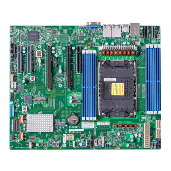
Introduction Congratulations on purchasing your computer motherboard from an industry leader. Supermicro motherboards are designed to provide you with the highest standards in quality and performance. In addition to the motherboard, several important parts that are included in the retail box are listed below. - Page 9 Chapter 1: Introduction Figure 1-1. X13SEI-TF Motherboard Image Note: All graphics shown in this manual were based upon the latest PCB revision available at the time of publication of the manual. The motherboard you received may or may not look exactly the same as the graphics shown in this manual.
- Page 10 Super X13SEI-TF/-F User's Manual Figure 1-2. X13SEI-F Motherboard Image Note: All graphics shown in this manual were based upon the latest PCB revision available at the time of publication of the manual. The motherboard you received may or may not look exactly the same as the graphics shown in this manual.
- Page 11 Chapter 1: Introduction Figure 1-3. X13SEI-TF Motherboard Layout (not drawn to scale) LED6 JUIDB1 USB4/5 (3.2 Gen 1) LEDBMC X550 LAN2 LAN1 USB0/1 BMC_LAN MH13 MH10 MH11 MH12 LED4 JM2_1 JPWR2 JM2_2 BAR CODE MAC CODE C741 JSD2 IPMI CODE...
-
Page 12: Quick Reference
Super X13SEI-TF/-F User's Manual Quick Reference SLOT7 LED6 BMC_LAN LAN2 LAN1 SLOT4 SLOT6 JUIDB1 SLOT2 USB4/5 USB0/1 (2.0) JNCSI1 SLOT1 LEDBMC (3.2 Gen 1) MH13 NVME2/3 LED6 JUIDB1 NVME0/1 USB4/5 FAN5 (3.2 Gen 1) LEDBMC X550 LAN2 LAN1 USB0/1 BMC_LAN... -
Page 13: Quick Reference Table
CMOS Clear Open (Normal) JPL1 LAN1 Enable/Disable (I210, X13SEI-F only) Pins 1-2 (Enabled) JPL2 LAN2 Enable/Disable (I210, X13SEI-F only) Pins 1-2 (Enabled) LAN 1/2 Enable/Disable (X550, X13SEI-TF JPL3 Pins 1-2 (Enabled) only) JPME1 ME Recovery Mode Pins 1-2 (Normal) Description... - Page 14 Super X13SEI-TF/-F User's Manual Connector Description LAN1, LAN2 LAN (RJ45) Ports MH10–MH13 M.2 Mounting Holes NVME0/1, NVME2/3 MCIO Connectors (PCIe 5.0 x8) SATA8, SATA9 SATA 3.0 Ports with SATA DOM Power SLOT1 PCIe 5.0 x8 Slot SLOT2 PCIe 5.0 x8 Slot SLOT4 PCIe 5.0 x16 Slot...
-
Page 15: Motherboard Features
Up to 2048GB of ECC RDIMM/RDIMM 3DS DDR5 memory with speeds of up to 4800MT/s in eight memory slots DIMM Size • 16GB, 32GB, 64GB, 128GB, 256GB Note: For the latest CPU/memory updates, refer to our website at http://www.supermicro.com/products/motherboard. Chipset • Intel PCH C741 Expansion Slots •... - Page 16 Super X13SEI-TF/-F User's Manual Motherboard Features Peripheral Devices • Two rear accessible USB 3.2 Gen 1 ports • One front accessible USB 3.2 Gen 1 header (one port only) • One USB 3.2 Gen 1 Type-A header • Two rear accessible USB 2.0 ports •...
- Page 17 Note 1: The CPU maximum thermal design power (TDP) is subject to chassis and heatsink cooling restrictions. For proper thermal management, check the chassis and heatsink specifications for proper CPU TDP sizing. Note 2: For IPMI configuration instructions, refer to the Embedded IPMI Configuration User's Guide available at http://www.supermicro.com/support/manuals/.
- Page 18 Super X13SEI-TF/-F User's Manual Figure 1-3. System Block Diagram CPU1-B1 CPU1-A1 CPU1-D1 CPU1-C1 CPU-G1 CPU-H1 CPU1-E1 CPU-F1 CPU1 DDR5 PECI:30 SOCKET ID:0 DDR5 SPR:4800 DMI3 #3A #3E SLOT 4 PCIe GEN5 x16 PCIe x16 JNVME2 PCIe GEN5 x8 SLOT 1...
-
Page 19: Processor And Chipset Overview
1.2 Processor and Chipset Overview Built upon the functionality and capability of the 4th Generation Intel Xeon Scalable Processor and the PCH C741 chipset, the X13SEI-TF/-F motherboard provides system performance, power efficiency, and feature sets to address the needs of next-generation computer users. -
Page 20: Fan Status Monitor With Firmware Control
Super X13SEI-TF/-F User's Manual Fan Status Monitor with Firmware Control The system health monitor embedded in the BMC chip can check the RPM status of the cooling fans. The CPU and chassis fans are controlled via lPMI. Environmental Temperature Control System Health sensors monitor temperatures and voltage settings of onboard processors and the system in real time via the IPMI interface. -
Page 21: Power Supply
It is even more important for processors that have high CPU clock rates where noisy power transmission is present. The X13SEI-TF/-F motherboard accommodates a 24-pin ATX power supply. Although most power supplies generally meet the specifications required by the CPU, some are inadequate. -
Page 22: Chapter 2 Installation
Super X13SEI-TF/-F User's Manual Chapter 2 Installation 2.1 Static-Sensitive Devices Electrostatic Discharge (ESD) can damage electronic com ponents. To avoid damaging your system board, it is important to handle it very carefully. The following measures are generally sufficient to protect your equipment from ESD. -
Page 23: Processor And Heatsink Installation
Thermal grease is pre-applied on a new heatsink. No additional thermal grease is needed. • Refer to the Supermicro website for updates on processor support. • All graphics in this manual are for illustration purposes only. Your components may look different. -
Page 24: Overview Of The Processor Carrier Assembly
Super X13SEI-TF/-F User's Manual Overview of the Processor Carrier Assembly The processor carrier assembly contains the Intel Xeon processor and a processor carrier. 1. Intel Xeon Processor 2. Processor Carrier Overview of the CPU Socket The CPU socket is protected by a plastic protective cover. -
Page 25: Overview Of The Processor Heatsink Module
Chapter 2: Installation Overview of the Processor Heatsink Module The Processor Heatsink Module (PHM) contains a heatsink, a processor carrier, and the Intel Xeon processor. 1. Heatsink with Thermal Grease 2. Processor Carrier 3. Intel Xeon Processor Processor Heatsink Module (PHM) Bottom View... -
Page 26: Creating The Processor Carrier Assembly
Super X13SEI-TF/-F User's Manual Creating the Processor Carrier Assembly To install a processor into the processor carrier, follow the steps below: 1. Before installation, make sure the lever on the processor carrier is pressed down as shown below. 2. Hold the processor with the LGA lands (gold contacts) facing up. Locate the small, gold triangle in the corner of the processor and the corresponding hollowed triangle on the processor carrier. -
Page 27: Assembling The Processor Heatsink Module
Chapter 2: Installation Assembling the Processor Processor Carrier Assembly Heatsink Module (Upside Down) After creating the processor carrier assembly Triangle on the CPU for the processor, mount it onto the heatsink to create the processor heatsink module (PHM): 1. Note the label on top of the heatsink, which marks the airflow direction. -
Page 28: Preparing The Cpu Socket For Installation
Super X13SEI-TF/-F User's Manual Preparing the CPU Socket for Installation This motherboard comes with a plastic protective cover installed on the CPU socket. Remove it from the socket to install the Processor Heatsink Module (PHM). Gently pull up one corner of the plastic protective cover to remove it. -
Page 29: Installing The Processor Heatsink Module
Chapter 2: Installation Installing the Processor Heatsink Module After assembling the Processor Heatsink Module (PHM), install it onto the CPU socket: 1. Align pin 1 of the PHM with the printed triangle on the CPU socket. See the left image below. -
Page 30: Removing The Processor Heatsink Module
Super X13SEI-TF/-F User's Manual Removing the Processor Heatsink Module Before removing the processor heatsink module (PHM) from the motherboard, shut down the system and then unplug the AC power cord from all power supplies. Then follow the steps below: 1. Use a T30 Torx-bit screwdriver to loosen the four screws. -
Page 31: Motherboard Installation
MH13 MH10 MH11 MH12 LED4 JM2_1 JPWR2 JM2_2 BAR CODE MAC CODE C741 JSD2 IPMI CODE SAN MAC JSD1 X13SEI-TF JBT1 REV:1.01 CMOS CLEAR DESIGNED IN USA JNVI2C1 BIOS LICENSE FAN4 FAN3 JSEN1 LEDPWR JRK1 FANB FANA JSTBY1 CHASSIS INTRUSION... -
Page 32: Installing The Motherboard
Super X13SEI-TF/-F User's Manual Installing the Motherboard 1. Install the I/O shield into the back of the chassis, if applicable. 2. Locate the mounting holes on the motherboard. See the previous page for the location. 3. Locate the matching mounting holes on the chassis. Align the mounting holes on the motherboard against the mounting holes on the chassis. -
Page 33: Memory Support And Installation
Memory Support The X13SEI-TF/-F supports up to 2048GB of ECC RDIMM/RDIMM 3DS DDR5 memory with speeds of up to 4800MT/s. Refer to the table below for the recommended DIMM population order. Note: Use one DIMM per channel when populating the channels. -
Page 34: General Guidelines For Optimizing Memory Performance
Super X13SEI-TF/-F User's Manual General Guidelines for Optimizing Memory Performance • It is recommended to use DDR5 memory of the same type, size, and speed. • Mixed DIMM speeds can be installed. However, all DIMMs will run at the speed of the slowest DIMM. -
Page 35: Dimm Installation
2. Push the release tabs outwards on both JM2_2 BAR CODE MAC CODE C741 JSD2 IPMI CODE SAN MAC JSD1 X13SEI-TF JBT1 REV:1.01 ends of the DIMM slot to unlock it. CMOS CLEAR DESIGNED IN USA JNVI2C1 BIOS LICENSE FAN4... -
Page 36: Rear I/O Ports
Super X13SEI-TF/-F User's Manual 2.5 Rear I/O Ports See Figure 2-1 below for the locations and descriptions of the various I/O ports on the rear of the motherboard. LED6 JUIDB1 USB4/5 (3.2 Gen 1) LEDBMC X550 LAN2 LAN1 USB0/1 BMC_LAN... - Page 37 Chapter 2: Installation LAN Ports Two Gigabit (X13SEI-F) or 10 Gigabit (X13SEI-TF) Ethernet ports (LAN1, LAN2) are located on the I/O back panel. In addition to the LAN ports, a dedicated IPMI LAN is located above the USB0/1 ports on the back panel. All of these ports accept RJ45 cables. Refer to the LED Indicator section for LAN LED information.
- Page 38 Super X13SEI-TF/-F User's Manual Unit Identifier Switch (UID-SW): One button with two functions A Unit Identifier (UID) switch and two LED Indicators are located on the motherboard. The UID switch is located next to the VGA port on the back panel.
- Page 39 LED4 JM2_1 3. USB4/5 4. USB6 JPWR2 JM2_2 BAR CODE MAC CODE 5. USB7 C741 JSD2 IPMI CODE SAN MAC JSD1 X13SEI-TF JBT1 REV:1.01 CMOS CLEAR DESIGNED IN USA JNVI2C1 BIOS LICENSE FAN4 FAN3 JSEN1 LEDPWR JRK1 FANB FANA JSTBY1...
-
Page 40: Front Control Panel
JF1 contains header pins for various buttons and indicators that are normally located on a control panel at the front of the chassis. These connectors are designed specifically for use with a Supermicro chassis. See the figure below for the descriptions of the front control panel buttons and LED indicators. - Page 41 Chapter 2: Installation Power Button The Power Button connection is located on pins 1 and 2 of JF1. Momentarily contacting both pins will power on/off the system. This button can also be configured to function as a suspend button (with a setting in the BIOS - see Chapter 4). To turn off the power when the system is in suspend mode, press the button for 4 seconds or longer.
- Page 42 Super X13SEI-TF/-F User's Manual Power Fail The Power Fail LED connection is located at pins 5 and 6. Refer to the table below for pin definitions. Power Fail LED Pin Definitions (JF1) Pin# Definition 3.3V Power Fail LED Information LED (OH/Fan Fail/PWR Fail/UID LED) The Information LED (OH/Fan Fail/PWR Fail/UID LED) connection is located on pins 7 and 8 of JF1.
- Page 43 Chapter 2: Installation NIC1/NIC2 (LAN1/LAN2) The NIC (Network Interface Controller) LED connection for LAN port 1 is located on pins 11 and 12 of JF1, and LAN port 2 is on pins 9 and 10. Attach the NIC LED cables here to display network activity.
- Page 44 Super X13SEI-TF/-F User's Manual Power LED The Power LED connection is located on pins 15 and 16 of JF1. Refer to the table below for pin definitions. Power LED Pin Definitions (JF1) Pins Definition +3.3V Stby PWR LED NMI Button The non-maskable interrupt button header is located on pins 19 and 20 of JF1.
-
Page 45: Connectors
3. 8-Pin CPU Power MH10 MH11 MH12 LED4 JM2_1 JPWR2 JM2_2 BAR CODE MAC CODE C741 JSD2 IPMI CODE SAN MAC JSD1 X13SEI-TF JBT1 REV:1.01 CMOS CLEAR DESIGNED IN USA JNVI2C1 BIOS LICENSE FAN4 FAN3 JSEN1 LEDPWR JRK1 FANB FANA JSTBY1... -
Page 46: Headers
Super X13SEI-TF/-F User's Manual Headers Chassis Intrusion A Chassis Intrusion header is located at JL1 on the motherboard. Attach the appropriate cable from the chassis to inform you of a chassis intrusion when the chassis is opened. Refer to the table below for pin definitions. - Page 47 3. JSD2 MH10 MH11 MH12 LED4 JM2_1 JPWR2 JM2_2 BAR CODE MAC CODE C741 JSD2 IPMI CODE SAN MAC JSD1 X13SEI-TF JBT1 REV:1.01 CMOS CLEAR DESIGNED IN USA JNVI2C1 BIOS LICENSE FAN4 FAN3 JSEN1 LEDPWR JRK1 FANB FANA JSTBY1 CHASSIS INTRUSION...
- Page 48 Super X13SEI-TF/-F User's Manual Fan Headers There are seven 4-pin fan headers (FAN1–FAN5, FANA, FANB) on the motherboard. All these 4-pin fan headers are backwards compatible with the traditional 3-pin fans. However, fan speed control is available for 4-pin fans only by Thermal Management via the IPMI 2.0 interface. Refer to the table below for pin definitions.
- Page 49 4. NVMe2/3 MH10 MH11 MH12 LED4 JM2_1 JPWR2 JM2_2 BAR CODE MAC CODE C741 JSD2 IPMI CODE SAN MAC JSD1 X13SEI-TF JBT1 REV:1.01 CMOS CLEAR DESIGNED IN USA JNVI2C1 BIOS LICENSE FAN4 FAN3 JSEN1 LEDPWR JRK1 FANB FANA JSTBY1 CHASSIS INTRUSION...
- Page 50 Baseboard Management Controller (BMC) and a Network Interface Controller (NIC). For the network sideband interface to work properly, you will need to use a NIC add-on card that supports NC-SI and also need to have a special cable. Please contact Supermicro at www.
- Page 51 This motherboard has nine SATA 3.0 ports located at JS1 (SATA0–7), SATA8, and SATA9. SATA0 can be used with Supermicro SuperDOM's SATA DOM connectors with power pins built in, and do not require external power cables. Supermicro SuperDOMs are backward compatible with regular SATA HDDs or SATA DOMs that need external power cables.
- Page 52 Super X13SEI-TF/-F User's Manual SMB I C for Expander The JI2C_EXP1 connector is used for System Management Bus (I2C) for the devices installed on the SAS3 backplanes. Connect appropriate cables to the connector for SAS3 health monitoring and system management. See the layout below for the connector location.
- Page 53 A Trusted Platform Module (TPM)/Port 80 header is located at JTPM1 to provide TPM support and Port 80 connection. Use this header to enhance system performance and data security. Refer to the table below for pin definitions. Visit the following link for more information on the TPM: http://www.supermicro.com/manuals/other/TPM.pdf. Trusted Platform Module Header Pin Definitions...
-
Page 54: Jumper Settings
Super X13SEI-TF/-F User's Manual 2.8 Jumper Settings How Jumpers Work To modify the operation of the motherboard, jumpers can be used to choose between optional settings. Jumpers create shorts between two pins to change the function of the connector. Pin 1 is identified with a square solder pad on the printed circuit board. - Page 55 Use JPL1 to enable or disable the I210 LAN1 port (for X13SEI-F). Use JPL2 to enable or disable the I210 LAN2 port (for X13SEI-F). Use JPL3 to enable or disable the X550 LAN1 and LAN2 ports (for X13SEI-TF). The default setting is Enabled. LAN Port Enable/Disable...
-
Page 56: Led Indicators
Super X13SEI-TF/-F User's Manual 2.9 LED Indicators BMC Heartbeat LED LEDBMC is the BMC Heartbeat LED. When the LED is blinking green, BMC is working. Refer to the table below for the LED status. BMC Heartbeat LED LED Color Definition... -
Page 57: Chapter 3 Troubleshooting
Chapter 3: Troubleshooting Chapter 3 Troubleshooting 3.1 Troubleshooting Procedures Use the following procedures to troubleshoot your system. If you have followed all of the procedures below and still need assistance, refer to the ‘Technical Support Procedures’ and/ or ‘Returning Merchandise for Service’ section(s) in this chapter. Always disconnect the AC power cord before adding, changing or installing any non hot-swap hardware components. -
Page 58: System Boot Failure
Super X13SEI-TF/-F User's Manual System Boot Failure If the system does not display Power-On-Self-Test (POST) or does not respond after the power is turned on, do the following: 1. Check the screen for an error message. 2. Clear the CMOS settings by unplugging the power cord and contacting both pads on the CMOS clear jumper (JBT1). -
Page 59: When The System Becomes Unstable
Chapter 3: Troubleshooting When the System Becomes Unstable A. If the system becomes unstable during or after OS installation, check the following: 1. CPU/BIOS support: Make sure that your CPU is supported and that you have the latest BIOS installed in your system. 2. - Page 60 Super X13SEI-TF/-F User's Manual 6. To find out if a component is good, swap this component with a new one to see if the system will work properly. If so, then the old component is bad. You can also install the component in question in another system.
-
Page 61: Technical Support Procedures
Before contacting Technical Support, take the following steps. Also, note that as a motherboard manufacturer, Supermicro also sells motherboards through its channels, so it is best to first check with your distributor or reseller for troubleshooting services. They should know of any possible problems with the specific system configuration that was sold to you. -
Page 62: Frequently Asked Questions
Updated BIOS files are located on our website at http://www. supermicro.com/ResourceApps/BIOS_IPMI_Intel.html. Check our BIOS warning message and the information on how to update your BIOS on our website. Select your motherboard model and download the BIOS file to your computer. Also, check the current BIOS revision to make sure that it is newer than your BIOS before downloading. -
Page 63: Battery Removal And Installation
Chapter 3: Troubleshooting 3.4 Battery Removal and Installation Battery Removal To remove the onboard battery, follow the steps below: 1. Power off your system and unplug your power cable. 2. Locate the onboard battery as shown below. 3. Using a tool such as a pen or a small screwdriver, push the battery lock outwards to unlock it. -
Page 64: Returning Merchandise For Service
Super X13SEI-TF/-F User's Manual 3.5 Returning Merchandise for Service A receipt or copy of your invoice marked with the date of purchase is required before any warranty service will be rendered. You can obtain service by calling your vendor for a Returned Merchandise Authorization (RMA) number. -
Page 65: Chapter 4 Uefi Bios
Chapter 4: UEFI BIOS Chapter 4 UEFI BIOS 4.1 Introduction This chapter describes the AMIBIOS™ Setup utility for the motherboard. The BIOS is stored on a chip and can be easily upgraded using the BMC WebUI or the SUM utility. Note: Due to periodic changes to the BIOS, some settings may have been added or deleted and might not yet be recorded in this manual. -
Page 66: Main Setup
Super X13SEI-TF/-F User's Manual 4.2 Main Setup When you first enter the AMI BIOS Setup utility, you will see the Main setup screen. You can always return to the Main Setup screen by selecting the Main tab on the top of the screen. - Page 67 Chapter 4: UEFI BIOS CPLD Version This feature displays the version of the Complex Programmable Logic Device (CPLD) used in the system. Memory Information Total Memory This feature displays the total size of memory available in the system.
-
Page 68: Advanced Setup Configurations
Super X13SEI-TF/-F User's Manual 4.3 Advanced Setup Configurations Use the arrow keys to select the Advanced submenu and press <Enter> to access the submenu items. Warning: Take caution when changing the Advanced settings. An incorrect value, an improper DRAM frequency, or a wrong BIOS timing setting may cause the system to malfunction. When this occurs, restore the setting to the manufacturer default setting. - Page 69 Chapter 4: UEFI BIOS Bootup NumLock State Use this feature to set the Power-on state for the <Numlock> key. The options are On and Off. Wait For "F1" If Error Select Enabled to force the system to wait until the <F1> key is pressed if an error occurs. The options are Disabled and Enabled.
- Page 70 Super X13SEI-TF/-F User's Manual CPU Configuration The following CPU information is displayed: • Processor BSP Revision • Processor Socket • Processor ID • Processor Frequency • Processor Max Ratio • Processor Min Ratio • Microcode Revision • L1 Cache RAM (Per Core) •...
- Page 71 Chapter 4: UEFI BIOS ENERGY_PERF_BIAS CFG Mode (ENERGY PERFORMANCE BIAS CONFIGURATION Mode) (Available when "Power Performance Tuning" is seet to BIOS Controls EPB) Use this feature to configure the proper operation setting for your machine by achieving the desired system performance level and energy saving (efficiency) level at the same time.
- Page 72 Super X13SEI-TF/-F User's Manual EIST PSD Function (Available when "SpeedStep (P-States)" is set to Enable) This feature reduces the latency that occurs when one P-state changes to another, thus allowing the transitions to occur more frequently. This feature allows for more demand- based P-state switching based on real-time energy needs of applications and optimize the power-to-performance balance for energy efficiency.
- Page 73 Chapter 4: UEFI BIOS Package C State Control Package C State Use this feature to optimize and reduce CPU package power consumption in the idle mode. Note that the changes you've made in this setting will affect all CPU cores or the circuits of the entire system.
- Page 74 Super X13SEI-TF/-F User's Manual LLC Prefetch If this feature is set to Enable, LLC (hardware cache) prefetching on all threads will be supported. The options are Disable and Enable. Homeless Prefetch Use this feature to enable or disable Homeless Prefetch on all threads. The options are Disable, Enable, and Auto.
- Page 75 Chapter 4: UEFI BIOS ---------------------------------------------------------------- TME, TME-MT, TDX ---------------------------------------------------------------- Memory Encryption (TME) Select Enabled for total memory encryption support to enhance memory data security. The options are Disabled and Enabled. Total Memory Encryption (TME) Bypass (Available when "Memory Encryption (TME)" is set to Enabled) Use this feature to disable/enable the Total Memory Encryption (TME) function for physical memory protection.
- Page 76 Super X13SEI-TF/-F User's Manual SW Guard Extensions (SGX) Use this feature to enable Intel Software Guard Extensions (SGX) support. Intel SGX is a set of extensions that increases the security of application code and data by using enclaves in memory to protect sensitive information. The options are Disabled and Enabled.
- Page 77 Chapter 4: UEFI BIOS Link L0p Enable Select Enable for the system BIOS to enable Link L0p support. This feature allows the CPU to reduce the UPI links from full width to half width in the event when the CPU's workload is low in an attempt to save power.
- Page 78 Super X13SEI-TF/-F User's Manual Stale AtoS The in-memory directory has three states: I, A, and S states. The I (-invalid) state indi- cates that the data is clean and does not exist in the cache of any other sockets. The A (-snoop All) state indicates that the data may exist in another socket in an exclusive or modified state.
- Page 79 Chapter 4: UEFI BIOS Legacy ADR Mode Use this feature to support the Legacy ADR mode to enhance memory performance. The options are Disable, Enable, and Auto. DDR 2x Refresh Enable Select Enable for memory 2X refresh support to enhance memory performance. The options are Auto, Diable, and Enable.
- Page 80 Super X13SEI-TF/-F User's Manual DDR PPR Type Post Package Repair (PPR) is a new feature available for the DDR4/DDR5 technology. PPR provides additional spare capacity within a DDR4/DDR5 DRAM module that is used to replace faulty cell areas detected during system boot. PPR offers two types of memory repairs.
- Page 81 Chapter 4: UEFI BIOS Data Link Feature Exchange Use this feature to enable or disable the data link feature negotiation in the Data Link Feature Capabilities (DLFCAP) register. The options are Disable and Enable. DMI Port MPSS This feature allows you to configure the Max Payload Size Supported in DMI Device Capabilities register.
- Page 82 Super X13SEI-TF/-F User's Manual PCIe ACSCTL Select Enable to program ACS control to Chipset PCIe Root Port bridges. Select Dis- able to program ACS control to all PCIe Root Port bridges. The options are Disable and Enable. Intel® VMD Technology ...
- Page 83 Chapter 4: UEFI BIOS Select Enable to enable Intel Volume Management Device (VMD) technology support for the root port specified. The options are Disable and Enable. CPU SLOT1 PCIe 5.0 X8 VMD / CPU SLOT2 PCIe 5.0 X8 VMD (Available when the device is detected by the system and "Enable/Disable VMD"...
- Page 84 Super X13SEI-TF/-F User's Manual Select Enable to enable Hot Plug support for the root ports specified. This feature allows you to change the devices on those root ports without shutting down the system. The options are Disable and Enable. VMD Config for IOU 4 Enable/Disable VMD Select Enable to enable Intel VMD technology support for the root port specified.
- Page 85 Chapter 4: UEFI BIOS IIO eDPC ERR_COR Message (Available if "IIO eDPC Support" is set to On Fatal Error or On Fatal and Non-Fatal Errors) Use this feature to enable or disable IIO enhanced DPC (eDPC) error correction mes- sage. The options are Disable and Enable. South Bridge The following USB information is displayed: •...
- Page 86 Super X13SEI-TF/-F User's Manual PCH SATA0 Configuration When the submenu is selected, the AMI BIOS automatically detects the presence of the SATA devices that are supported by the Intel PCH chip and displays the following features. SATA Controller(s) This feature enables or disables the onboard SATA controller supported by the Intel PCH chip.
- Page 87 Chapter 4: UEFI BIOS SATA Device Type Use this feature to specify if the device installed on the SATA port you specified should be connected to a Solid State drive or a Hard Disk Drive. The options are Hard Disk Drive and Solid State Drive.
- Page 88 Super X13SEI-TF/-F User's Manual Spin Up Device Select Enable for Staggered Spin Up support. This feature allows the SATA devices you specified to spin up one at a time at boot up in an effort to prevent all hard drive disks from spinning up at the same time, causing a power surge.
- Page 89 The options are Disabled and Enabled. Supermicro BIOS-Based TPM Provision Support If this feature is set to Enabled, Supermicro BIOS-based TPM provision will be supported. The options are Disabled and Enabled. Note: Enabling this feature will lock your TPM on the production platform, and you will...
- Page 90 Super X13SEI-TF/-F User's Manual TXT Support Select Enabled to enable Intel Trusted Execution Technology (TXT) support to enhance system integrity and data security. The options are Disabled and Enabled. Note 1: If this feature is set to Enabled, be sure to disable Device Function On-Hide (EV DFX) support when it is present in the BIOS for the system to work properly.
- Page 91 Chapter 4: UEFI BIOS Serial Port 1 Configuration This submenu allows you to configure the settings of Serial Port 1. Serial Port 1 Select Enabled to enable the selected onboard serial port. The options are Disabled and Enabled. Device Settings This feature displays the base I/O port address and the Interrupt Request address of serial port 1.
- Page 92 Super X13SEI-TF/-F User's Manual Serial Port Console Redirection COM1 Console Redirection Select Enabled to enable COM port 1 for Console Redirection. This feature allows a client machine to be connected to a host machine at a remote site for networking. The options are Disabled and Enabled.
- Page 93 Chapter 4: UEFI BIOS Flow Control Use this feature to set the flow control for Console Redirection to prevent data loss caused by buffer overflow. Send a "Stop" signal to stop sending data when the receiving buffer is full. Send a "Start" signal to start sending data when the receiving buffer is empty. The options are None and Hardware RTS/CTS.
- Page 94 Super X13SEI-TF/-F User's Manual Bits Per Second Use this feature to set the transmission speed for a serial port used in Console Redirection. Make sure that the same speed is used in the host computer and the client computer. A lower transmission speed may be required for long and busy lines.
- Page 95 Chapter 4: UEFI BIOS Legacy Console Redirection Legacy Console Redirection Settings Legacy Serial Redirection Port Use this feature to select a COM port to display redirection of Legacy OS and Legacy OPROM messages. The options are COM1 and SOL. Resolution Use this feature to select the number of rows and columns used in Console Redirection for Legacy OS support.
- Page 96 Super X13SEI-TF/-F User's Manual Bits Per Second EMS This feature sets the transmission speed for a serial port used in Console Redirection. Make sure that the same speed is used in the host computer and the client computer. A lower transmission speed may be required for long and busy lines. The options are 9600, 19200, 57600, and 115200 (bits per second).
- Page 97 Chapter 4: UEFI BIOS Media Detect Count Use this feature to select the wait time (in seconds) for the BIOS ROM to detect the presence of a LAN media either via the Internet connection or via a LAN port. Press <+> or <-> on your keyboard to change the value.
- Page 98 Super X13SEI-TF/-F User's Manual Save Changes and Exit Select this feature to save the changes for the features above and exit. MAC:xxxxxxxxxxxx-IPv4 Network Configuration MAC:xxxxxxxxxxxx-IPv4 Network Configuration Configured Select Enabled to show whether the network address has been successfully configured. The options are Disabled and Enabled.
- Page 99 Chapter 4: UEFI BIOS PCIe/PCI/PnP Configuration The following information is displayed: • PCI Bus Driver Version PCI Devices Common Settings: Above 4G Decoding (Available if the system supports 64-bit PCI decoding) Select Enabled to decode a PCI device that supports 64-bit in the space above 4G Address. The options are Disabled and Enabled.
- Page 100 Super X13SEI-TF/-F User's Manual NVMe Firmware Source Use this feature to select the NVMe firmware to support booting. The default option, Vendor Defined Firmware, is pre-installed on the drive and may resolve errata or enable innovative functions for the drive. The other option, AMI Native Support, is offered by the BIOS with a generic method.
- Page 101 Use this feature to enter the SMCI Key Management Service (KMS) server IPv4 address in dotted-decimal notation (e.g., 255.255.255.255). Second Supermicro KMS Server IP address Use this feature to enter the second SMCI KMS server IPv4 address in dotted-decimal notation (e.g., 255.255.255.255).
- Page 102 Super-Guardians Configuration Super Guardians is a unified security solution to facilitate KMS, TPM, or USB-based authentication controls for Supermicro X13 motherboards. Use this submenu to configure the authentication policy, method, and KMS server settings. Super-Guardians Protection Policy Use this feature to enable the Super-Guardians Protection Policy. The options are Storage, System, and "System and Storage."...
- Page 103 Note 1: Be sure that the KMS server is ready before configuring this feature. Note 2: Use the professional KMS server solutions (e.g., Thales Server) or the Supermicro PyKMIP Software Package to establish the KMS server. When this feature has previously been set to Enabled, the options are Enabled, Reset, and Key Rotation.
- Page 104 Super X13SEI-TF/-F User's Manual Save Authentication-Key Use this feature to toggle whether the BIOS should automatically save an Authentication-Key with the name TPMAuth.bin to a USB flash drive. The options are Disabled and Enabled. After an Authentication Key is saved, this option will be reset to Disabled. Changes take effect after you save settings and reboot the system.
- Page 105 Chapter 4: UEFI BIOS NIC Configuration Link Speed Wake On LAN If this feature is set to Enabled, the LAN port you specified will be enabled when the system is powered on. The options are Disabled and Enabled. Blink LEDs Use this feature to identify the physical network port by blinking the associated LED. The default setting is 0 (up to 15 seconds).
- Page 106 Super X13SEI-TF/-F User's Manual Certification GUID Press <Enter> and input the certification Global Unique Identifier (GUID). Commit Changes and Exit Use this feature to save all changes and exit TLS settings. Discard Changes and Exit Use this feature to discard all changes and exit TLS settings.
-
Page 107: Event Logs
Chapter 4: UEFI BIOS 4.4 Event Logs Use this menu to configure Event Log settings. Note: The changes take effect after you press Save Changes and Exit, Save Changes and Reset, or Save Changes in the Save and Exit submenu. Change SMBIOS Event Log Settings Enabling/Disabling Options SMBIOS Event Log... - Page 108 Super X13SEI-TF/-F User's Manual SMBIOS Event Log Standard Settings Log System Boot Event (Available when "SMBIOS Event Log" is set to Enabled) Select Enabled to log system boot events. The options are Enabled and Disabled. MECI (Multiple Event Count Increment) (Available when "SMBIOS Event Log" is set to Enabled) Enter the increment value for the multiple event counter.
-
Page 109: Bmc
Chapter 4: UEFI BIOS 4.5 BMC Use this menu to configure BMC settings. BMC Firmware Revision This feature indicates the IPMI firmware revision used in your system. BMC STATUS (Baseboard Management Controller) This feature indicates the status of the IPMI firmware installed in your system. System Event Log Enabling/Disabling Options SEL Components... - Page 110 Super X13SEI-TF/-F User's Manual When SEL is Full This feature allows you to determine what the BIOS should do when the system event log is full. Select Erase Immediately to erase all events in the log when the system event log is full.
- Page 111 Chapter 4: UEFI BIOS Station MAC Address (Available when "Configuration Address Source" is set to Static) This feature displays the Station MAC address for this computer. Mac addresses are six two-digit hexadecimal numbers. Gateway IP Address This feature displays the Gateway IP address for this computer. This should be in decimal and in dotted quad form (i.e., 172.29.0.1).
- Page 112 Super X13SEI-TF/-F User's Manual Gateway IP (Available when "Configuration Address Source" is set to Static Configuration) Use this feature to enter the IPv6 gateway IP address. Press <Enter> to change the setting. Advanced Settings This feature allows you to automatically obtain the DNS server IP or manually obtain the DNS server IP.
-
Page 113: Security
The length of the password should be from three characters to 20 characters long. Note: For detailed instructions on how to configure Security Boot settings, refer to the Security Boot Configuration User's Guide posted on the web page under the link: http://www.supermicro.com/support/manuals/. - Page 114 • HDD User Pwd Status: This feature indicates if a password has been set as a SATA user password which allows you to configure Supermicro Security Erase settings on the HDD (SATA) device by using this SATA user password. •...
- Page 115 Note: For detailed instructions on how to configure Security Boot settings, refer to the Security Boot Configuration User's Guide posted on the web page under the link: http:// www.supermicro.com/support/manuals/. This section displays the contents of the following secure boot features: •...
- Page 116 Super X13SEI-TF/-F User's Manual Enter Audit Mode (Available when "Secure Boot Mode" is set to Custom) Select Ok to enter the Audit Mode workflow. It will result in erasing of Platform Key (PK) variables and reset system to the Setup/Audit Mode.
- Page 117 Chapter 4: UEFI BIOS Platform Key (PK) Use this feature to enter and configure a set of values to be used as platform firmware keys for the system. These values also indicate the sizes, keys numbers, and the sources of the authorized signatures.
-
Page 118: Boot
Super X13SEI-TF/-F User's Manual 4.7 Boot Use this menu to configure Boot settings. Boot Mode Select Use this feature to select the type of devices from which the system will boot. The options are Legacy, UEFI, and Dual. Note: When "Boot Mode Select" is set to Dual, all OPROM-related features will be set to Legacy. - Page 119 Chapter 4: UEFI BIOS When "Boot Mode Select" is set to UEFI, the following features will be displayed for configuration: • Boot Option #1–Boot Option #9 When "Boot Mode Select" is set to Dual, the following features will be displayed for configuration: •...
-
Page 120: Save & Exit
Super X13SEI-TF/-F User's Manual 4.8 Save & Exit Use this menu to save settings and exit from the BIOS. Save Options Discard Changes and Exit Use this feature to exit from the BIOS Setup utility without making any permanent changes to the system configuration and reboot the computer. - Page 121 Chapter 4: UEFI BIOS Default Options Restore Optimized Defaults Select this feature and press <Enter> to load manufacturer optimized default settings. The default settings are intended for maximum system performance but not for maximum stability. Save as User Defaults Select this feature and press <Enter> to save all changes on the default values specified to the BIOS Setup utility for future use.
-
Page 122: Appendix A Bios Codes
Super X13SEI-TF/-F User's Manual Appendix A BIOS Codes A.1 BIOS Error POST (Beep) Codes During the Power-On Self-Test (POST) routines, which are performed each time the system is powered on, errors may occur. Non-fatal errors are those which, in most cases, allow the system to continue the boot up process. - Page 123 Appendix A: BIOS Codes A.2 Additional BIOS POST Codes The AMI BIOS supplies additional checkpoint codes, which are documented online at http:// www.supermicro.com/support/manuals/ ("AMI BIOS POST Codes User's Guide"). For information on AMI updates, refer to http://www.ami.com/products/.
-
Page 124: Appendix B Software
1. Create a method to access the MS Windows installation ISO file. That can be a USB flash or media drive. 2. Retrieve the proper RST/RSTe driver. Go to the Supermicro web page for your motherboard and click on "Download the Latest Drivers and Utilities", select the proper driver, and copy it to a USB flash drive. - Page 125 Appendix B: Software 4. During Windows Setup, continue to the dialog where you select the drives on which to install Windows. If the disk you want to use is not listed, click on “Load driver” link at the bottom left corner. Figure B-2.
- Page 126 Super X13SEI-TF/-F User's Manual B.2 Driver Installation The Supermicro website that contains drivers and utilities for your system is at https://www. supermicro.com/wdl/driver/. Some of these must be installed, such as the chipset driver. After accessing the website, go into the CDR_Images (in the parent directory of the above link) and locate the ISO file for your motherboard.
- Page 127 B.3 SuperDoctor ® The Supermicro SuperDoctor 5 is a program that functions in a command-line or web-based interface for Windows and Linux operating systems. The program monitors such system health information as CPU temperature, system voltages, system power consumption, fan speed, and provides alerts via email or Simple Network Management Protocol (SNMP).
- Page 128 Interface (IPMI). IPMI is used to provide remote access, monitoring and management. There are several BIOS settings that are related to IPMI. Supermicro ships standard products with a unique password for the BMC ADMIN user. This password can be found on a label on the motherboard. For general documentation and information on IPMI, visit our website at https://www.supermicro.com/en/support/BMC_...
-
Page 129: Appendix C Standardized Warning Statements
The following statements are industry standard warnings, provided to warn the user of situations which have the potential for bodily injury. Should you have questions or experience difficulty, contact Supermicro's Technical Support department for assistance. Only certified technicians should attempt to install or configure components. - Page 130 Super X13SEI-TF/-F User's Manual Attention Danger d'explosion si la pile n'est pas remplacée correctement. Ne la remplacer que par une pile de type semblable ou équivalent, recommandée par le fabricant. Jeter les piles usagées conformément aux instructions du fabricant. ¡Advertencia! Existe peligro de explosión si la batería se reemplaza de manera incorrecta.
- Page 131 Appendix C: Standardized Warning Statements Product Disposal Warning! Ultimate disposal of this product should be handled according to all national laws and regulations. 製品の廃棄 この製品を廃棄処分する場合、 国の関係する全ての法律 ・ 条例に従い処理する必要があります。 警告 本产品的废弃处理应根据所有国家的法律和规章进行。 警告 本產品的廢棄處理應根據所有國家的法律和規章進行。 Warnung Die Entsorgung dieses Produkts sollte gemäß allen Bestimmungen und Gesetzen des Landes erfolgen.
-
Page 132: Appendix D Uefi Bios Recovery
Warning: Do not upgrade the BIOS unless your system has a BIOS-related issue. Flashing the wrong BIOS can cause irreparable damage to the system. In no event shall Supermicro be liable for direct, indirect, special, incidental, or consequential damages arising from a BIOS update. - Page 133 USB device or a USB flash or media drive. Note 1: If you cannot locate the "Super.ROM" file in your driver disk, visit our website www.supermicro.com to download the BIOS package. Extract the BIOS binary im- age into a USB flash device and rename it "Super.ROM" for the BIOS recovery use.
- Page 134 Super X13SEI-TF/-F User's Manual 2. Insert the USB device that contains the new BIOS image ("Super.ROM") into your USB port and reset the system until the following screen appears: 3. After locating the new BIOS binary image, the system will enter the BIOS Recovery menu as shown below: Note: At this point, you may decide if you want to start the BIOS recovery.
- Page 135 Appendix D: UEFI BIOS Recovery 4. When the screen as shown above displays, use the arrow keys to select the item "Proceed with flash update" and press the <Enter> key. You will see the BIOS recovery progress as shown in the screen below: Note: Do not interrupt the BIOS flashing process until it has completed.
- Page 136 Super X13SEI-TF/-F User's Manual 8. When the UEFI Shell prompt appears, type fs# to change the device directory path. Go to the directory that contains the BIOS package you extracted earlier from Step 6. Enter flash.nsh BIOSname.### at the prompt to start the BIOS update process.
Need help?
Do you have a question about the X13SEI-TF and is the answer not in the manual?
Questions and answers