Table of Contents
Advertisement
Quick Links
Advertisement
Table of Contents

Related Manuals for Supermicro X13SCL-IF


Summary of Contents for Supermicro X13SCL-IF
- Page 1 X13SCL-IF USER'S MANUAL Revision 1.0...
- Page 2 State of California, USA. The State of California, County of Santa Clara shall be the exclusive venue for the resolution of any such disputes. Supermicro's total liability for all claims will not exceed the price paid for the hardware product.
- Page 3 V0 - LGA1700 socket with up to eight cores and a thermal design power (TDP) of 95 W. Built with the Intel C262 PCH chipset, the X13SCL-IF supports 64 GB DDR5 ECC UDIMM memory with speeds of up to 4800 MT/s, SATA 3.0, M.2, and a Trusted Platform Module (TPM) header.
- Page 4 Super X13SCL-IF User's Manual Contacting Supermicro Headquarters Address: Super Micro Computer, Inc. 980 Rock Ave. San Jose, CA 95131 U.S.A. Tel: +1 (408) 503-8000 Fax: +1 (408) 503-8008 Email: Marketing@supermicro.com (General Information) Sales-USA@supermicro.com (Sales Inquiries) Government_Sales-USA@supermicro.com (Gov. Sales Inquiries) Support@supermicro.com (Technical Support) RMA@supermicro.com...
-
Page 5: Table Of Contents
Preface Table of Contents Chapter 1 Introduction 1.1 Checklist ..........................8 Quick Reference .......................11 Quick Reference Table ......................12 Motherboard Features .......................14 1.2 Processor and Chipset Overview ..................17 1.3 Special Features ........................17 Recovery from AC Power Loss ..................17 1.4 System Health Monitoring ....................17 Onboard Voltage Monitors ....................17 Environmental Temperature Control .................18 1.5 ACPI Features ........................18... - Page 6 Super X13SCL-IF User's Manual 2.6 Front Control Panel ......................37 2.7 Connectors .........................42 Power Connections ......................42 Headers ..........................43 2.8 Jumper Settings .........................48 How Jumpers Work ......................48 2.9 LED Indicators ........................52 Chapter 3 Troubleshooting 3.1 Troubleshooting Procedures ....................54 Before Power On ......................54 No Power ..........................54...
- Page 7 Preface Appendix A BIOS Codes Appendix B Software Appendix C Standardized Warning Statements Appendix D UEFI BIOS Recovery...
-
Page 8: Checklist
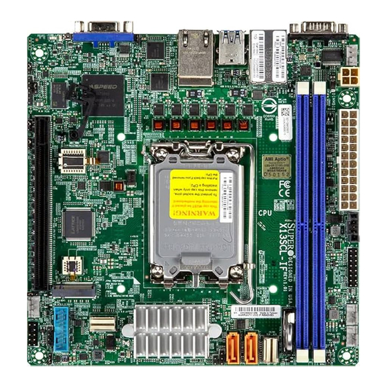
Introduction Congratulations on purchasing your computer motherboard from an industry leader. Supermicro motherboards are designed to provide you with the highest standards in quality and performance. In addition to the motherboard, several important parts that are included in the retail box are listed below. - Page 9 Chapter 1: Introduction Figure 1-1. X13SCL-IF Motherboard Image Note: All graphics shown in this manual were based upon the latest PCB revision available at the time of publication of the manual. The motherboard you received may or may not look exactly the same as the graphics shown in this manual.
- Page 10 Super X13SCL-IF User's Manual Figure 1-2. X13SCL-IF Motherboard Layout (not drawn to scale) JUIDB1 COM1 JPL1 JPL1:LAN1 1-2:ENABLE 2-3:DISABLE USB2/3 (3.2(5Gb)) JPW2 BMC_LAN LAN1/2 USB0/1 Controller JMD1_SRW1 JPL2:LAN2 1-2:ENABLE 2-3:DISABLE BIOS LICENSE JMD1 JTPM1:TPM/PORT80 JWD1:WATCH DOG 1-2:RST 2-3:NMI JPME2: JWD1...
-
Page 11: Quick Reference
Chapter 1: Introduction Quick Reference LED1 LED2 BMC_LAN LEDM1 LAN1/2 USB 2/3 COM1 USB0/1 JPL1 JUIDB1 JUIDB1 COM1 JPL1 JPL1:LAN1 FAN3 1-2:ENABLE 2-3:DISABLE JPG1 USB2/3 (3.2(5Gb)) JPW2 JPW2 JRF1 BMC_LAN LAN1/2 USB0/1 Controller JMD1_SRW1 JMD1_SRW1 JPL2:LAN2 1-2:ENABLE 2-3:DISABLE JPL2 DIMMA1 BIOS LICENSE DIMMB1 JPW1... -
Page 12: Quick Reference Table
Super X13SCL-IF User's Manual Quick Reference Table Jumper Description Default Setting JBT1 CMOS Clear Open (Normal) Pins 1–2 (4x SATA) JNS1 SATA 3.0 or PCIe 4.0 Selection Pins 2–3 (PCIe x4) JPG1 VGA Enable/Disable Pins 1–2 (Enabled) JPL1 LAN1 Enable/Disable Pins 1–2 (Enabled) - Page 13 Chapter 1: Introduction Connector Description USB2/3 Back Panel USB 3.2 Gen 1 Ports USB4/5 Front Panel USB 3.2 Gen 1 Header VGA Port...
-
Page 14: Motherboard Features
Note: This motherboard supports 4800 MT/s with the one DIMM per channel population configuration. DIMM Size • 8 GB, 16 GB, 32 GB at 1.1 V Note: For the latest CPU/memory updates, refer to our website at http://www.supermicro.com/products/motherboard. Chipset • Intel C262 PCH Expansion Slots •... - Page 15 Chapter 1: Introduction Motherboard Features Power Management • ACPI power management • Power button override mechanism • Power-on mode for AC power recovery • Wake up on LAN System Health Monitoring • Onboard voltage monitoring for +3.3 V, +5 V, +12 V, +3.3 VStb, +5 Vstb, Vcore, Vmem, CPU temperature, PCH temperature, system temperature, memory temperature, peripheral temperature •...
- Page 16 Super X13SCL-IF User's Manual Figure 1-3. System Block Diagram 4800 MT/s support is limited to 1R1R configurations. (64 GB) Up to 128 GB ECC UDIMM (2933 MT/s) DDR5 (CHA) INTEL LGA1700 PCIe 5.0 x16 DIMMA1 JPCIe1 PCIe 5.0 x16 (Socket-V) PCIe 4.0 x4...
-
Page 17: Processor And Chipset Overview
Built upon the functionality and capability of the Intel Xeon E-2400 or 12th Generation Pentium processor (V0 - LGA1700), and the Intel C262 PCH chipset, the X13SCL-IF motherboard provides system performance, power efficiency, and feature sets to address the needs of next-generation computer users. -
Page 18: Environmental Temperature Control
It is recommended that you also install a power surge protector to help avoid problems caused by power surges. 1.7 Serial Port The X13SCL-IF motherboard has one serial port on the I/O back panel. -
Page 19: Chapter 2 Installation
Chapter 2: Installation Chapter 2 Installation 2.1 Static-Sensitive Devices Electrostatic Discharge (ESD) can damage electronic com ponents. To avoid damaging your system board, it is important to handle it very carefully. The following measures are generally sufficient to protect your equipment from ESD. Precautions •... -
Page 20: Processor And Heatsink Installation
If you buy a CPU separately, make sure that you use an Intel-certified multi-directional heatsink only. • Refer to the Supermicro website for updates on processor support. • All graphics in this manual are for illustrations only. Your components may look different. - Page 21 Chapter 2: Installation 2. Gently push down the load lever to release and lift it, then lift the load plate to open it completely. Lever lock 3. Use your thumb and your index finger to hold the CPU. Align the small triangle maker and notches on the CPU to the corresponding triangle maker and notches on the CPU load bracket.
- Page 22 Super X13SCL-IF User's Manual 6. Close the load plate with the CPU inside the socket. Gently push the load lever down until it locks under the Lever Lock latch. Lever lock Attention! You can only install the CPU inside the socket in one direction. Make sure that it is properly inserted into the CPU socket before closing the load plate.
-
Page 23: Installing A Cpu Heatsink
Chapter 2: Installation Installing a CPU Heatsink Note 1: The installation described in this section is for reference only. The actual in- stallation steps may vary depending on the CPU heatsink model. Refer to the heatsink instruction for more details. Note 2: Graphic drawings included in this manual are for reference only. - Page 24 Super X13SCL-IF User's Manual 3. Attach the backplate into the mounting holes around the CPU socket on the bottom side of the motherboard. Backplate bottom side Motherboard bottom side Mounting hole Motherboard Top side...
- Page 25 Chapter 2: Installation 4. Apply the proper amount of thermal grease on the CPU. 5. Place the heatsink on top of the CPU so that the four mounting holes on the heatsink are aligned with those on the retention mechanism. 6.
-
Page 26: Removing A Cpu Heatsink
Super X13SCL-IF User's Manual Removing a CPU Heatsink Warning: We do not recommend that the CPU or heatsink be removed. However, if you do need to remove the heatsink, follow the instructions below to uninstall the heatsink to avoid damaging the CPU or other components. -
Page 27: Motherboard Installation
Chapter 2: Installation 2.3 Motherboard Installation All motherboards have standard mounting holes to fit different types of chassis. Make sure that the locations of all the mounting holes for both the motherboard and the chassis match. Although a chassis may have both plastic and metal mounting fasteners, metal ones are highly recommended because they ground the motherboard to the chassis. -
Page 28: Installing The Motherboard
Super X13SCL-IF User's Manual Installing the Motherboard 1. Install the I/O shield into the back of the chassis, if applicable. 2. Locate the mounting holes on the motherboard. See the previous page for the location. 3. Locate the matching mounting holes on the chassis. Align the mounting holes on the motherboard against the mounting holes on the chassis. -
Page 29: Memory Support And Installation
Memory Support The X13SCL-IF motherboard supports up to 64 GB of DDR5 ECC UDIMM memory with speeds of up to up to 4800 MT/s (with the one or two DIMM(s) per channel configurations) in two memory slots. Refer to the table below for the recommended DIMM population order. -
Page 30: General Guidelines For Optimizing Memory Performance
Super X13SCL-IF User's Manual General Guidelines for Optimizing Memory Performance • It is recommended to use DDR5 memory of the same type, size, and speed. • The motherboard will support odd-numbered modules (one module installed). However, to achieve the best memory performance, a balanced memory population is recommended. -
Page 31: Dimm Installation
Chapter 2: Installation DIMM Installation JUIDB1 COM1 1. Insert DIMM modules in the following JPL1 JPL1:LAN1 1-2:ENABLE 2-3:DISABLE USB2/3 (3.2(5Gb)) order: DIMMA1 and DIMMB1. For the JPW2 BMC_LAN LAN1/2 USB0/1 Controller system to work properly, use memory modules of the same type and speed. JMD1_SRW1 JPL2:LAN2 1-2:ENABLE... -
Page 32: Rear I/O Ports
Super X13SCL-IF User's Manual 2.5 Rear I/O Ports See Figure 2-1 below for the locations and descriptions of the various I/O ports on the rear of the motherboard. JUIDB1 COM1 JPL1 JPL1:LAN1 1-2:ENABLE 2-3:DISABLE USB2/3 (3.2(5Gb)) JPW2 BMC_LAN LAN1/2 USB0/1... - Page 33 Chapter 2: Installation LAN Ports Two Gigabit Ethernet ports (LAN1/2) are located on the I/O back panel. In addition to the LAN ports, a dedicated BMC LAN on the back panel. All of these ports accept RJ45 cables. Refer to the LED Indicator section for LAN LED information. LAN Port BMC LAN Pin Definition...
- Page 34 Super X13SCL-IF User's Manual Universal Serial Bus (USB) Ports There are two USB 2.0 ports (USB0/1) on the I/O back panel. The motherboard also has two USB 3.2 Gen 1 ports (USB2/3) on the I/O back panel and one front access USB 3.2 Gen 1 header (USB4/5).
- Page 35 Chapter 2: Installation COM Port There is one COM port on the I/O back panel. Refer to the board layout below for the locations. COM Port (COM1) Pin Definitions Pin# Definition Pin# Definition Ground VGA Port A video (VGA) port is located on the I/O back panel. Refer to the board layout below for the location.
- Page 36 Super X13SCL-IF User's Manual Unit Identifier Switch/UID LED Indicator A Unit Identifier (UID) switch and an LED indicator are located on the motherboard. The UID switch is located at JUIDB1, which is next to the VGA port on the back panel. The UID LED (LED2) is located next to the UID switch.
-
Page 37: Front Control Panel
JF1 contains header pins for various buttons and indicators that are normally located on a control panel at the front of the chassis. These connectors are designed specifically for use with Supermicro chassis. See the figure below for the descriptions of the front control panel buttons and LED indicators. - Page 38 Super X13SCL-IF User's Manual Power Button The Power Button connection is located on pins 1 and 2 of JF1. Momentarily contacting both pins will power on/off the system. This button can also be configured to function as a suspend button (with a setting in the BIOS - see Chapter 4). To turn off the power when the system is in suspend mode, press the button for 4 seconds or longer.
- Page 39 Chapter 2: Installation Power Fail LED The Power Fail LED connection is located on pins 5 and 6 of JF1. Refer to the table below for pin definitions. Power Fail LED Pin Definitions (JF1) Pin# Definition 3.3 V PWR Supply Fail Overheat (OH)/Fan Fail Connect an LED cable to pins 7 and 8 of the Front Control Panel to use the Overheat/Fan Fail LED connections.
- Page 40 Super X13SCL-IF User's Manual NIC1/NIC2 (LAN1/LAN2) The NIC (Network Interface Controller) LED connection for LAN port 1 is located on pins 11 and 12 of JF1, and LAN port 2 is on pins 9 and 10. Attach the NIC LED cables here to display network activity.
- Page 41 Chapter 2: Installation Power LED The Power LED connection is located on pins 15 and 16 of JF1. Refer to the table below for pin definitions. Power LED Pin Definitions (JF1) Pins Definition +3.3 VStby PWR LED 1. Power LED Ground Power Button Reset Button...
-
Page 42: Connectors
Super X13SCL-IF User's Manual 2.7 Connectors Power Connections ATX Power Supply Connector The primary 24-pin power supply connector (JPW1) meets the ATX SSI EPS 12 V specification. The 4-pin (JPW2) processor power connector must also be connected to your power supply. -
Page 43: Headers
Chapter 2: Installation Headers Chassis Intrusion A Chassis Intrusion header is located at JL1 on the motherboard. Attach the appropriate cable from the chassis to be informed of a chassis intrusion when the chassis is opened. Refer to the table below for pin definitions. Chassis Intrusion Pin Definitions Pin#... - Page 44 Super X13SCL-IF User's Manual M.2 Slot This motherboard has one M.2 slot. M.2 was formerly known as Next Generation Form Factor (NGFF) and serves to replace mini PCIe. M.2 allows for increased functionality and spatial efficiency. The M.2 slot on the motherboard supports PCIe 4.0 x4 SSD cards in the 2280 form factor.
- Page 45 Chapter 2: Installation SATA 3.0 Ports This motherboard has two SATA 3.0 ports. I-SATA4/5 can be used with Supermicro SuperDOMs that are yellow SATA DOM connectors with power pins built in and do not require external power cables. Supermicro SuperDOMs are backwards compatible with regular SATA HDDs or SATA DOMs that need external power cables.
- Page 46 Super X13SCL-IF User's Manual Speaker On the JD1 header, pins 1–4 are for the speaker. If you wish to use an external speaker, connect its cable to pins 1–4. Speaker Connector Pin Definitions Pin # Definition 1–4 Speaker System Management Bus Header A System Management Bus header for additional slave devices or sensors is located at JSMB1.
- Page 47 Port 80 connection. Use this header to enhance system performance and data security. Refer to the table below for pin definitions. Go to the following link for more information on the TPM: https://www.supermicro.com/manuals/other/TPM.pdf. Trusted Platform Module/Port80 Header Pin Definitions...
-
Page 48: Jumper Settings
Super X13SCL-IF User's Manual 2.8 Jumper Settings How Jumpers Work To modify the operation of the motherboard, jumpers can be used to choose between optional settings. Jumpers create shorts between two pins to change the function of the connector. Pin 1 is identified with a square solder pad on the printed circuit board. See the diagram below for an example of jumping pins 1 and 2. - Page 49 Chapter 2: Installation CPU PCIe Bifurcation Set the JRF1 jumper to set the PCIe lanes to either x16 or two x8 for Slot 7. PCIe Bifurcation Jumper Settings Jumper Setting Definition Pins 1–2 Pins 2–3 Two x8 LAN1 Enable/Disable Use jumper JPL1 to enable or disable LAN port 1 and jumper JPL2 to enable or disable LAN port 2.
- Page 50 Super X13SCL-IF User's Manual ME Manufacturing Mode Close pins 2-3 of jumper JPME2 to bypass SPI flash security and force the system to operate in the manufacturing mode, which allows you to flash the system firmware from a host server for system setting modifications.
- Page 51 Chapter 2: Installation VGA Enable/Disable JPG1 allows you to enable or disable the VGA port using the onboard graphics controller. VGA Enable/Disable Jumper Settings Jumper Setting Definition Pins 1–2 Enabled Pins 2–3 Disabled Watch Dog Timer Watch Dog (JWD1) is a system monitor that can reboot the system when a software application hangs.
-
Page 52: Led Indicators
Super X13SCL-IF User's Manual 2.9 LED Indicators BMC Heartbeat LED LEDM1 is the BMC Heartbeat LED. When the LED is blinking green, BMC is working. Refer to the table below for the LED status. BMC Heartbeat LED LED Color Definition... - Page 53 Chapter 2: Installation LAN LEDs Two LAN ports (LAN1/2) are located on the I/O back panel. Each LAN port has two LEDs. The green LED indicates activity, while the other Link LED may be yellow, amber, or off to indicate the speed of the connection. Refer to the tables below for more information. LAN Activity LED (Left) LAN Link LED (Right) LED State...
-
Page 54: Chapter 3 Troubleshooting
Super X13SCL-IF User's Manual Chapter 3 Troubleshooting 3.1 Troubleshooting Procedures Use the following procedures to troubleshoot your system. If you have followed all of the procedures below and still need assistance, refer to the ‘Technical Support Procedures’ and/ or ‘Returning Merchandise for Service’ section(s) in this chapter. Always disconnect the AC power cord before adding, changing or installing any non hot-swap hardware components. -
Page 55: No Video
Chapter 3: Troubleshooting No Video 1. If the power is on, but you have no video, remove all add-on cards and cables. 2. Use the speaker to determine if any beep codes are present. Refer to Appendix A for details on beep codes. 3. -
Page 56: Losing The System's Setup Configuration
Super X13SCL-IF User's Manual 3. Make sure that you are using the correct type of ECC DDR5 modules recommended by the manufacturer. 4. Check for bad DIMM modules or slots by swapping a single module among all memory slots and check the results. - Page 57 Chapter 3: Troubleshooting B. If the system becomes unstable before or during OS installation, check the following: 1. Source of installation: Make sure that the devices used for installation are working properly, including boot devices such a USB flash or media drive. 2.
-
Page 58: Technical Support Procedures
Before contacting Technical Support, take the following steps. Also, note that as a motherboard manufacturer, Supermicro also sells motherboards through its channels, so it is best to first check with your distributor or reseller for troubleshooting services. They should know of any possible problems with the specific system configuration that was sold to you. -
Page 59: Frequently Asked Questions
Note: The SPI BIOS chip used on this motherboard cannot be removed. Send your motherboard back to our RMA Department at Supermicro for repair. For BIOS Recov- ery instructions, refer to the AMI BIOS Recovery Instructions posted at https://www. -
Page 60: Battery Removal And Installation
Super X13SCL-IF User's Manual 3.4 Battery Removal and Installation Battery Removal To remove the onboard battery, follow the steps below: 1. Power off your system and unplug your power cable. 2. Locate the onboard battery as shown below. 3. Using a tool such as a pen or a small screwdriver, push the battery lock outwards to unlock it. -
Page 61: Returning Merchandise For Service
For faster service, you can also request a RMA authorization online (https://www.supermicro. com/RmaForm/). This warranty only covers normal consumer use and does not cover damages incurred in shipping or from failure due to the alternation, misuse, abuse or improper maintenance of products. -
Page 62: Chapter 4 Uefi Bios
Super X13SCL-IF User's Manual Chapter 4 UEFI BIOS 4.1 Introduction This chapter describes the AMIBIOS™ Setup utility for the motherboard. The BIOS is stored on a chip and can be easily upgraded using a flash program. Note: Due to periodic changes to the BIOS, some settings may have been added or deleted and might not yet be recorded in this manual. -
Page 63: Main Setup
The date must be entered in MM/DD/YYYY format. The time is entered in HH:MM:SS format. Note: The time is in the 24-hour format. For example, 5:30 P.M. appears as 17:30:00. Supermicro X13SCL-IF BIOS Version This feature displays the version of the BIOS ROM used in the system. - Page 64 Super X13SCL-IF User's Manual Memory Information Total Memory This feature displays the total size of memory available in the system.
-
Page 65: Advanced Setup Configurations
Chapter 4: UEFI BIOS 4.3 Advanced Setup Configurations Use the arrow keys to select the Advanced submenu and press <Enter> to access the submenu items. Warning: Take caution when changing the Advanced settings. An incorrect value, an improper DRAM frequency, or a wrong BIOS timing setting may cause the system to malfunction. When this occurs, revert the setting to the manufacture default settings. - Page 66 Super X13SCL-IF User's Manual Bootup NumLock State Use this feature to set the Power-on state for the <Numlock> key. The options are On and Off. Wait For "F1" If Error Select Enabled to force the system to wait until the <F1> key is pressed if an error occurs.
- Page 67 Chapter 4: UEFI BIOS Power Button Function This feature controls how the system shuts down when the power button is pressed. Select 4 Seconds Override for you to power off the system after pressing and holding the power button for four seconds or longer. Select Instant Off to instantly power off the system as soon as you presses the power button.
- Page 68 Super X13SCL-IF User's Manual Adjacent Cache Line Prefetch If this feature is set to Disabled, the CPU will prefetch cache lines for 64 bytes. If set to Enabled, the CPU will prefetch cache lines for 128 bytes as comprised. The options are Disabled and Enabled.
- Page 69 Chapter 4: UEFI BIOS Select Enabled to use the Intel Advanced Encryption Standard (AES) to ensure data security. The options are Disabled and Enabled. Machine Check Use this feature to enable or disable Machine Check. The options are Disabled and Enabled. Monitor MWait Select Enable to support Monitor and Mwait, which are two instructions in Streaming SIMD Extension 3 (SSE3) to improve synchronization between multiple threads for CPU performance...
- Page 70 Super X13SCL-IF User's Manual HwP Autonomous Epp Grouping Use this feature to enable or disable Hardware-Controlled Performance States (HwP) Autonomous Energy Performance Preference (EPP) Grouping. When this feature is set to enabled, the same value will be requested for all cores with the same EPP. When this feature is set to disabled, requests will not necessarily be the same value for all cores with the same EPP.
- Page 71 Chapter 4: UEFI BIOS Power Limit 2 Power (Available when "Power Limit 2" is set to Enabled) Use this feature to configure Package Power Limit 2 in milliwatts or milli-percents. For example, to set Power Limit 2 Power to 12%, enter 12000. The BIOS will round to the nearest 1/8 W or 1/8%.
- Page 72 Super X13SCL-IF User's Manual Power Limit 4 Override Use this feature to enable or disable Platform Power Limit 4 (PsysPL4) override When this feature is set to Enabled, Power Limit 4 and Power Limit 4 Lock can be configured. The options are Disabled and Enabled.
- Page 73 Chapter 4: UEFI BIOS IO MWait Redirection Use this feature to redirect IO_read instructions sent to IO register PMG_IO_BASE_ ADDRBASE+offset to MWAIT(offset). The options are Disabled and Enabled. Package C-State Limit Use this feature to set the Package C-State limit. The options are C0/C1, C2, C3, C6, C7, C7S, C8, C9, C10, Cpu Default, and Auto.
- Page 74 Super X13SCL-IF User's Manual Maximum Memory Frequency This feature selects the speed of the memory installed. The default setting is Auto. All values are in MT/s. ECC Support Use this feature to enable or disable DDR ECC support. The options are Disabled and Enabled.
- Page 75 Chapter 4: UEFI BIOS Power Down Mode Use this feature to set the Clock-Enable (CKE) power down mode. When this feature is set to No Power Down, CKE is disabled. When this feature is set to Active Power-down (APD), open pages are retained when de-asserting CKE. When this feature is set to Pre-charged Power-down (PPD) Delayed-locked Loop off (DLLoff), DDR enters a deep power-down state when all rows are pre-charged.
- Page 76 Super X13SCL-IF User's Manual PCIe Speed Use this feature to select the PCI Express port speed. The options are Auto, Gen1, Gen2, Gen3, and Gen4. CPU SLOT7 PCIe 5.0 x16 This feature indicates if PCIe 5.0 x16 is present. PCI Express Root Port2 Use this feature to disable or enable the PCIe root port.
- Page 77 Chapter 4: UEFI BIOS X2APIC Opt Out Use this feature to enable or disable the X2APIC Opt Out Bit. The options are Enabled and Disabled. DMA Control Guarantee Use this feature to enable or disable Direct Memory Access (DMA) Control Guarantee. The options are Enabled and Disabled.
- Page 78 Super X13SCL-IF User's Manual Super IO Configuration Super IO Configuration • Super IO Chip - AST2600 Serial Port 1 Configuration Serial Port 1 Configuration Serial Port 1 This feature will enable or disable the serial port. The options are Disabled or Enabled.
- Page 79 Chapter 4: UEFI BIOS Serial Port Console Redirection COM1 /SOL Console Redirection / SOL Console Redirection Use this feature to enable the console redirection support for a serial port specified by you. The options for COM1 Console Redirection are Disabled and Enabled. The options for SOL Console Redirection are Disabled and Enabled.
- Page 80 Super X13SCL-IF User's Manual Flow Control Use this feature to set the flow control for Console Redirection to prevent data loss caused by buffer overflow. Send a "Stop" signal to stop sending data when the receiving buffer is full. Send a "Start" signal to start sending data when the receiving buffer is empty. The options are None and Hardware RTS/CTS.
- Page 81 Chapter 4: UEFI BIOS Serial Port for Out-Of-Band Management/Windows Emergency Management Services (EMS) Console Redirection EMS Select Enabled to use a COM port EMS Console Redirection. The options are Disabled and Enabled. Console Redirection Settings Out-of-Band Mgmt Port This feature selects a serial port in a client server to be used by the Microsoft Windows Emergency Management Services (EMS) to communicate with a remote host server.
- Page 82 Super X13SCL-IF User's Manual SATA And VROC Configuration SATA And VROC Configuration SATA Controller(s) This feature enables SATA device(s). The options are Disabled and Enabled. *If this feature is set to Enabled, the following features will become available for configuration: SATA Mode Selection Use this feature select the SATA mode.
- Page 83 Chapter 4: UEFI BIOS • Recovery FIrmware Version • ME Firmware Status #1 • ME Firmware Status #2 • Current State • Error Code ACPI Settings High Precision Event Timer Select Enabled to activate the High Precision Event Timer (HPET). The HPET produces periodic interrupts at a much higher frequency than a Real-time Clock (RTC) does in synchronizing multimedia streams, providing smooth playback, and reducing the dependency on other timestamp calculation devices.
- Page 84 Super X13SCL-IF User's Manual USB Mass Storage Driver Support This feature enables USB mass storage driver support. The options are Disabled and Enabled. Mass Storage Devices: STT USB_RM2M 1100 Select Auto to enumerate devices according to their media format. The options are Auto, Floppy, Forced FDD, Hard Disk, and CD-ROM.
- Page 85 Chapter 4: UEFI BIOS PCIe/PCI/PnP Configuration CPU SLOT7 PCIe 5.0 X16 OPROM / PCI / PCIX / PCIe Slot 4 OPROM Select EFI to boot the computer with the EFI device installed on the specified PCIe slot. The options are Disabled and EFI. M.2-C PCIe 4.0 x4 OPROM Select EFI to boot the computer with the EFI device installed on the specified M.2 slot.
- Page 86 Super X13SCL-IF User's Manual PXE boot wait time (Available when "Network Stack" is set to Enabled) Enter a value for the wait time (in seconds) to press the <ESC> key to abort the PXE boot. The default is 0. Media detect count (Available when "Network Stack" is set to Enabled) Enter a value for the number of times the presence of media will be checked.
- Page 87 Chapter 4: UEFI BIOS • Route Table • Gateway addresses • DNS addresses Interface ID Enter an ID for the device. DAD Transmit Count Enter a value for Duplicate Address Detection (DAD) Transmit Count. A value of zero indicates the DAD is not performed. The default is 1. Policy Use this feature to set the Policy.
- Page 88 Super X13SCL-IF User's Manual Trusted Computing When a Trusted-Platform Module (TPM) device is detected in your machine, the following information will display: • TPM 2.0 Device Found • Firmware Version • Vendor Security Device Support Select Enable to enable BIOS support for onboard security devices, which are not displayed in the OS.
- Page 89 Chapter 4: UEFI BIOS Storage Hierarchy (Available when "Security Device Support" is set to Enabled) Select Enabled for TPM Storage Hierarchy support that is intended to be used for non-privacy- sensitive operations by a platform owner such as an IT professional or the end user. Storage Hierarchy has an owner policy and an authorization value, both of which can be set and are held constant (-rarely changed) through reboots.
- Page 90 The options are Enabled and Disabled (WARNING: Security Risk!!). Warning: Disabling this option is a violation of RFC 6125 and may expose you to Man-in-the-Middle Attacks. Supermicro is not responsible for any and all security risks incurred by you disabling this option. Priority of HTTP Boot Instance of Priority 1 Use this feature to rank the targeted port.
- Page 91 Use this feature to enter the second Supermicro KMS server IPv4 address in dotted-decimal notation. Supermicro KMS TCP Port number Use this feature to enter the Supermicro KMS TCP port number. The valid range is 100 – 9999. The default setting is 5696. KMS Time Out Use this feature to enter the KMS server connecting time-out (in seconds).
- Page 92 Super-Guardians Configuration Super Guardians is a unified security solution to facilitate KMS, TPM, or USB-based authentication controls for Supermicro X13 motherboards. Use this submenu to configure the authentication policy, method, and KMS server settings. Super-Guardians Protection Policy Use this feature to enable the Super-Guardians Protection Policy. The options are Storage, System, and "System and Storage."...
- Page 93 Chapter 4: UEFI BIOS KMS Server Retry Count Use this feature to specify how many times the system will attempt reconnecting to the KMS server. Press <+> or <-> on your keyboard to change the value. The default setting is 5. If the value is 0, the system will retry infinitely.
- Page 94 Super X13SCL-IF User's Manual TLS Authenticate Configuration This submenu allows you to configure Transport Layer Security (TLS) settings. Server CA Configuration Enroll Certification Enroll Certification Using File Use this feature to enroll certification from a file. Certification GUID Use this feature to input the certification Global Unique Identifier (GUID).
- Page 95 Chapter 4: UEFI BIOS Commit Changes and Exit Use this feature to save all changes and exit TLS settings. Discard Changes and Exit Use this feature to discard all changes and exit TLS settings. Delete Certification Use this feature to delete certification. Intel(R) I210 Gigabit Network Connection - XX:XX:XX:XX:XX:XX Intel(R) I210 Gigabit Network Connection - XX:XX:XX:XX:XX:XX Firmware Image Properties...
- Page 96 Super X13SCL-IF User's Manual Blink LEDs (range 0–15 seconds) Use this feature to identify the physical network port by blinking the associated LED. Highlight this feature and enter a number of seconds in the range of 0 to 15 to set the amount of seconds to blink the LED.
-
Page 97: Event Logs
Chapter 4: UEFI BIOS 4.4 Event Logs Use this feature to configure Event Log settings. Change SMBIOS Event Log Settings Enabling/Disabling Options SMBIOS Event Log Change this feature to enable or disable all features of the SMBIOS Event Logging during system boot. - Page 98 Super X13SCL-IF User's Manual SMBIOS Event Log Standard Settings Log System Boot Event This option toggles the System Boot Event logging to enabled or disabled. The options are Enabled and Disabled. MECI The Multiple Event Count Increment (MECI) counter counts the number of occurrences that a duplicate event must happen before the MECI counter is incremented.
-
Page 99: Bmc
Chapter 4: UEFI BIOS 4.5 BMC Use this feature to configure Baseboard Management Console (BMC) settings. BMC Firmware Revision This feature indicates the IPMI firmware revision used in your system. BMC STATUS This feature indicates the status of the IPMI firmware installed in your system. System Event Log Enabling/Disabling Options SEL Components... - Page 100 Super X13SCL-IF User's Manual When SEL is Full (Available when "SEL Components" is set to Enabled) This feature allows you to decide what the BIOS should do when the system event log is full. Select Erase Immediately to erase all events in the log when the system event log is full. The options are Do Nothing and Erase Immediately.
- Page 101 Chapter 4: UEFI BIOS *If the Configuration Address Source is set to Static, the following features will become available for configuration: Station IP Address This feature displays the Station IP address for this computer. This should be in decimal and in dotted quad form (i.e., 192.168.10.253).
- Page 102 Super X13SCL-IF User's Manual *If the feature above is set to Enabled, the following feature will become available for configuration: Configuration Address Source This feature allows you to select the source of the IP address for this computer. If Static is selected, you will need to know the IP address of this computer and enter it to the system manually in the field.
-
Page 103: Security
Chapter 4: UEFI BIOS 4.6 Security This menu allows you to configure the following security settings for the system. Administrator Password This feature indicates if an administrator password has been set. Press <Enter> to create a new or change an existing administrator password. The length of the password can be between three to 20 characters long. - Page 104 Super X13SCL-IF User's Manual Lockdown Mode Use this feature to disable or enable Lockdown Mode. Lockdown Mode prevents existing data or keys stored in the system from being altered or changed to preserve system integrity and security. The options are Disabled and Enabled.
- Page 105 Note: CSM support is limited to following the Intel Server UEFI Strict Class 3 defini- tion. Supermicro can ensure the legacy boot will function properly, but if there are any device compatibility issues, the BIOS might not be able to resolve them.
- Page 106 Super X13SCL-IF User's Manual Reset To Setup Mode (Available when any secure keys have been installed) This feature resets the system to the Setup Mode. The options are Yes and No. Enroll Efi Image This feature allows the image to run in the secure boot mode. Enroll SHA256 Hash cer- tificate of a PE image into the Authorized Signature Database (DB).
- Page 107 Chapter 4: UEFI BIOS Forbidden Signatures (dbx) Use this feature to enter and configure a set of values to be used as Forbidden Signa- tures for the system. These values also indicate sizes, key numbers, and key sources of the forbidden signatures.
-
Page 108: Boot
Super X13SCL-IF User's Manual 4.7 Boot Use this feature to configure Boot Settings: Setup Prompt Timeout Use this feature to set the number of seconds to wait for the BIOS Setup activation key. The default value is 1. Set this value to 65535 (0xFFFF) to wait indefinitely. - Page 109 Chapter 4: UEFI BIOS Add New Boot Option (Available when any storage device is detected by the BIOS) Use this feature to add a new boot option to the boot priority features for system boot. Add boot option Use this feature to specify the name for the new boot option. Path for boot option Use this feature to enter the path for the new boot option in the format fsx:\path\filename.efi.
-
Page 110: Save & Exit
Super X13SCL-IF User's Manual 4.8 Save & Exit Use this feature to save the configurations or leave the BIOS Setup utility. Save Options Discard Changes and Exit Select this feature to leave the BIOS Setup utility without making any permanent changes to the system configuration, and reboot the computer. - Page 111 Chapter 4: UEFI BIOS Default Options Restore Optimized Defaults Select this feature and press <Enter> to load the optimized defaults. These are factory settings designed for maximum system stability but not for maximum performance. Save As User Defaults Select this feature and press <Enter> to save as the user defaults. This enables you to save any changes to the BIOS setup for future use.
- Page 112 Super X13SCL-IF User's Manual Appendix A BIOS Codes A.1 BIOS Error POST (Beep) Codes During the POST (Power-On Self-Test) routines, which are performed each time the system is powered on, errors may occur. Non-fatal errors are those which, in most cases, allow the system to continue the boot up process.
- Page 113 Appendix A: BIOS Codes A.2 Additional BIOS POST Codes The AMI BIOS supplies additional checkpoint codes, which are documented online at https:// www.supermicro.com/support/manuals/ ("AMI BIOS POST Codes User's Guide"). For information on AMI updates, please refer to https://www.ami.com/products/.
- Page 114 1. Create a method to access the MS Windows installation ISO file. That can be a USB flash or media drive. 2. Retrieve the proper VROC driver. Go to the Supermicro web page for your motherboard and click on "Download the Latest Drivers and Utilities," select the proper driver, and copy it to a USB flash drive.
- Page 115 Appendix B: Software 4. During Windows Setup, continue to the dialog where you select the drives on which to install Windows. If the disk you want to use is not listed, click on “Load driver” link at the bottom left corner. Figure B-2.
- Page 116 Super X13SCL-IF User's Manual B.2 Driver Installation The Supermicro website that contains drivers and utilities for your system is at https://www. supermicro.com/wdl/driver/. Some of these must be installed, such as the chipset driver. After accessing the website, go into the CDR_Images (in the parent directory of the above link) and locate the ISO file for your motherboard.
- Page 117 The following statements are industry standard warnings, provided to warn the user of situations which have the potential for bodily injury. Should you have questions or experience difficulty, contact Supermicro's Technical Support department for assistance. Only certified technicians should attempt to install or configure components.
- Page 118 Super X13SCL-IF User's Manual Attention Danger d'explosion si la pile n'est pas remplacée correctement. Ne la remplacer que par une pile de type semblable ou équivalent, recommandée par le fabricant. Jeter les piles usagées conformément aux instructions du fabricant. ¡Advertencia! Existe peligro de explosión si la batería se reemplaza de manera incorrecta.
- Page 119 Appendix C: Standardized Warning Statements Product Disposal Warning! Ultimate disposal of this product should be handled according to all national laws and regulations. 製品の廃棄 この製品を廃棄処分する場合、 国の関係する全ての法律 ・ 条例に従い処理する必要があります。 警告 本产品的废弃处理应根据所有国家的法律和规章进行。 警告 本產品的廢棄處理應根據所有國家的法律和規章進行。 Warnung Die Entsorgung dieses Produkts sollte gemäß allen Bestimmungen und Gesetzen des Landes erfolgen.
- Page 120 Warning: Do not upgrade the BIOS unless your system has a BIOS-related issue. Flashing the wrong BIOS can cause irreparable damage to the system. In no event shall Supermicro be liable for direct, indirect, special, incidental, or consequential damages arising from a BIOS update.
- Page 121 USB flash or media drive. Note: If you cannot locate the "Super.ROM" file in your driver disk, visit our website at https://www.supermicro.com to download the BIOS package. Extract the BIOS binary image into a USB flash device and rename it "Super.ROM" for the BIOS recovery use.
- Page 122 Super X13SCL-IF User's Manual Note 2: Before recovering the main BIOS image, confirm that the "Super.ROM" bi- nary image file you download is the same version or a close version meant for your motherboard. 2. Insert the USB device that contains the new BIOS image ("Super.ROM") into your USB port and reset the system until the following screen appears: 3.
- Page 123 Appendix D: UEFI BIOS Recovery 4. When the screen as shown above displays, use the arrow keys to select the item "Proceed with flash update" and press the <Enter> key. You will see the BIOS recovery progress as shown in the screen below: Note: Do not interrupt the BIOS flashing process until it has completed.
- Page 124 Super X13SCL-IF User's Manual 8. When the UEFI Shell prompt appears, type fs# to change the device directory path. Go to the directory that contains the BIOS package you extracted earlier from Step 6. Enter flash.nsh BIOSname.### at the prompt to start the BIOS update process.
Need help?
Do you have a question about the X13SCL-IF and is the answer not in the manual?
Questions and answers