Table of Contents
Advertisement
Quick Links
Advertisement
Table of Contents

Related Manuals for bora Professional 3.0


Summary of Contents for bora Professional 3.0
- Page 1 Installation instructions Professional 3.0 004563-10001 www.bora.com...
-
Page 2: Table Of Contents
4.6.3 Example bore holes ..........22 4.6.4 Fitting the control knob ..........22 Planning variations for PKA3/PKA3AB ....23 4.7.1 Airflow straight to the side........23 4.7.2 Airflow towards the left ..........23 4.7.3 Rotating the cover frame by 180° ......24 www.bora.com... -
Page 3: General Information
Results of non-compliance Liability Measures to minimise risk . BORA Holding GmbH, BORA Vertriebs GmbH & Co KG, BORA APAC Please note: Pty Ltd and BORA Lüftungstechnik GmbH – hereinafter referred to as warning symbols draw attention to a high risk of injury. -
Page 4: Safety
Incorrect components can lead to personal injury or BORA does not assume any liability for damages caused by damage to the appliance. Modifications, additions or incorrect installation, improper use or incorrect operation. -
Page 5: Safety Information For Installation
In the event of any faults or errors that are not Do not install or connect any damaged mentioned, switch the appliance off and contact appliances. BORA Service. Do not operate any damaged appliances. PLEASE NOTE ö DANGER Appliance damage caused by pets... -
Page 6: Safety Instructions - Cooktop Extractor Installation
(e.g. window contact switch, low disconnected from the mains with a contact pressure warning device) and have them opening width of at least 3 mm (circuit breaker approved by a qualified expert (certified chimney and automatic circuit breakers, fuses, contactor). sweep). www.bora.com... -
Page 7: Safety Instructions - Repairs, Servicing And Spare Parts
Safely disconnect the appliance from the mains supply. Work on electrical components must only be conducted by trained electrical personnel. A damaged power supply cable must be replaced by a suitable power supply cable. www.bora.com... -
Page 8: Technical Data
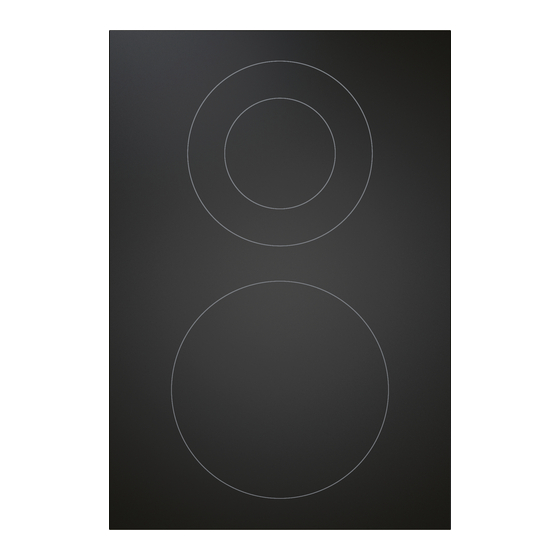
Dimensions (width x depth x height) 468 x 540 x 199 mm Weight (incl. accessories and packaging) 12.5 kg Cooktop extractor Power levels 1–9, P Technical data for PKAS3/PKAS3AB Tab. 3.2 Fig. 3.1 PKA3/PKA3AB appliance dimensions from above Fig. 3.2 PKA3/PKA3AB appliance dimensions front view www.bora.com... -
Page 9: Surface Induction Cooktop Pkfi3
Rear cooking zone (180 mm) 176.5 Wh/kg Cooking zones bridged (210 mm) 204.4 Wh/kg Total (average) 188.6 Wh/kg Technical data for PKFI3 Tab. 3.3 PKFI3 appliance dimensions Fig. 3.6 PKAS3/PKAS3AB appliance dimensions front view Fig. 3.7 PKAS3/PKAS3AB appliance dimensions side view Fig. 3.8 PKFI3 appliance dimensions from above www.bora.com... -
Page 10: Induction Cooktop Pki3
370 x 540 x 128 mm Weight (incl. accessories and packaging) 9.5 kg Cooktop Power levels 1–9, P Heat retention levels Cooking zone size Ø 310 mm Cooking zone output 2400 W Cooking zone power setting output 3000 W Technical data for PKIW3 Tab. 3.5 www.bora.com... -
Page 11: Hilight Cooktop, 3-Ring/2-Ring Pkc3
Power consumption (calculated with standard pot sizes) Front cooking zone (240 mm) 180.1 Wh/kg Fig. 3.15 PKIW3 appliance dimensions front view Rear cooking zone (210 mm) 189.0 Wh/kg Total (average) 184.6 Wh/kg Technical data for PKC3 Tab. 3.6 Fig. 3.16 PKIW3 appliance dimensions side view www.bora.com... -
Page 12: Hilight Cooktop, 3-Ring/Roaster Pkcb3
Power consumption (calculated with standard pot sizes) Fig. 3.18 PKC3 appliance dimensions front view Front cooking zone (240 mm) 180.6 Wh/kg Rear cooking zone (180 mm) 189.5 Wh/kg Total (average) 185.1 Wh/kg Technical data for PKCB3 Tab. 3.7 Fig. 3.19 PKC3 appliance dimensions side view www.bora.com... -
Page 13: Hyper Cooktop, 1-Ring/2-Ring Pkch3
Front cooking zone (240 mm) 175.9 Wh/kg Rear cooking zone (210 mm) 189.1 Wh/kg Total (average) 182.5 Wh/kg Technical data for PKCH3 Tab. 3.8 PKCH3 appliance dimensions Fig. 3.21 PKCB3 appliance dimensions front view Fig. 3.22 PKCB3 appliance dimensions side view Fig. 3.23 PKCH3 appliance dimensions from above www.bora.com... -
Page 14: Tepan Stainless Steel Grill Pkt3
2400 W Fig. 3.27 PKT3 appliance dimensions front view Rear cooking zone size 295 x 230 mm Rear cooking zone output 2400 W Temperature control range 70 - 250 °C Technical data for PKT3 Tab. 3.9 Fig. 3.28 PKT3 appliance dimensions side view www.bora.com... -
Page 15: Gas Cooktop Pkg3
Ø 49 mm x 92 mm Cooking zones bridged 60.0% Tab. 3.11 Technical data for control knob Tab. 3.10 Technical data for PKG3 Control knob dimensions PKG3 appliance dimensions Fig. 3.32 Control knob Fig. 3.29 PKG3 appliance dimensions from above Fig. 3.33 Control knob dimensions www.bora.com... -
Page 16: Installation
System functions the installation is checked and approved by an authorised certified Pause function engineer (e.g. heating engineer). Short-time timer Child lock All settings/functions in the configuration menu www.bora.com... -
Page 17: Checking The Scope Of Delivery
Checking the scope of delivery Make sure the delivery is complete and check it for damage. Additional scope of delivery for gas cooktop Immediately inform the BORA Service TeamTeam if parts are Cast-iron pan support missing or damaged. Nozzle set G20/20 mbar natural gas PKGDS2020 Do not under any circumstances install parts which are damaged. -
Page 18: Assembly Instructions
Minimum installation dimensions for standard set-up of PKA3/PKA3AB Taking into account the applicable valid regulations, the cooktop must be connected to the gas line with an upstream stopcock. The connection between the gas cooktop and the gas connection must be provided at the installation site. www.bora.com... -
Page 19: Return Flow Of Recirculated Air
(≥ 1000 cm² in the case of gas appliances) for each cooktop Make sure that the area below the cooktop has a sufficient air extractor. supply. Fig. 4.7 Air supply at front of the unit Air supply via the front of the unit (opening cross-section ≥50 cm²) Optional cable protection (shortened) www.bora.com... -
Page 20: Cut-Out Dimensions
Please note the worktop overhang x when creating the worktop cut- out. Applies to flush installation and surface mounting. 1709 1681 ≥ 60 Cut-out dimensions of the appliance combinations in the Tab. 4.3 case of flush installation ≥ 74 Fig. 4.10 Worktop overhang www.bora.com... -
Page 21: Surface Mounting
Cooktops/cooktop extractor B in mm Cooktop extractor Worktop Fixed front panel 4.6.2 Cooktop bore holes 1310 1681 Cut-out dimensions of the appliance combinations in the Tab. 4.4 case of surface mounting Fig. 4.17 Cooktop drilling pattern Cooktop Worktop Fixed front panel www.bora.com... -
Page 22: Example Bore Holes
Bore holes for control knobs (x 5) Knob housing Cooktop (x 2) Universal nut Cooktop extractor Sticker Worktop Knob ring Fixed front panel Wave spring Fig. 4.20 Drilling pattern for 3 cooktops, 2 cooktop extractors and 2 sockets Fig. 4.22 Fitting the control knob www.bora.com... -
Page 23: Planning Variations For Pka3/Pka3Ab
Curved duct piece Separate the curved duct piece from the duct piece adapter. To do this, carefully prise the plug connection open with a slotted screwdriver first. Pull the curved duct piece out. If necessary, rotate the cover frame by 180°. www.bora.com... -
Page 24: Rotating The Cover Frame By 180
Fig. 4.29 Removing the cover frame Turn the cooktop extractor round and remove the cover frame. Rotate the cover frame by 180°. Put the cover frame back on the cooktop extractor. Make sure that the holding clamps click into place. www.bora.com... -
Page 25: Securing The Cooktop Extractor
To do this, cut the mounting brackets at the appropriate cut marks using a utility knife. Depending on the installation type, turn the mounting brackets to the left or right (flush installation or surface mounting). www.bora.com... -
Page 26: Installing The Duct System
Fig. 4.37 Tightening the mounting clamps Installing the duct system BORA does not assume any liability for the installation of the Ecotube duct system. Fire safety requirements are to be Fig. 4.41 Duct connection dimensions for PKAS3, PKAS3AB clarified with the local authorities prior to installing the Ecotube duct system. -
Page 27: Preparing For Installation
150 mm or the BORA Ecotube duct system. Use only BORA Ecotube duct parts. Do not use flexible or fabric hoses. The duct system must be fitted to the cooktop extractor free of load and with the power supply switched off. -
Page 28: Positioning The Control Unit
Make sure the power to the appliance is disconnected. Use only BORA Universal fans. Check the gas type and gas pressure of the gas supply pipe. Ensure that the appliance is equipped with the correct nozzle type 4.10... -
Page 29: 4.10.5 Changing The Gas Type
Turn off the gas supply to the gas supply pipe. G30/31: 30 mbar Switch off the main switch/automatic circuit breaker. Secure the main switch/automatic circuit breaker against being Overview of gas categories Tab. 4.5 switched back on without permission. Make sure the power to the appliance is disconnected. www.bora.com... - Page 30 7.4 Mj/h ayarlamak: Doğal gaz H I2H 20 mbar Total nominal connection value for NG/1.0 kPa test- 19.5 Mj/h point pressure: Gas cooktop default settings Tab. 4.6 Cooktop energy consumption AU/NZ – NG/1.00 kPa test-point pressure: High-power burner 12.0 Mj/h Normal burner 7.5 Mj/h www.bora.com...
-
Page 31: Installing The Cooktops
If burner parts are not positioned correctly, the electric igniter will not work. Place the pan support straight on the gas burner so it fits perfectly. Fig. 4.49 Cooktop burner with gas burner nozzle Gas burner Gas burner nozzle www.bora.com... -
Page 32: 4.11.2 Installing The Cooktop
For a normal installation, please note that the ports for the control knobs and the automatic extractor function are at the rear. Fig. 4.52 Inserting the cooktop Control knob port and cooktop extractor interface (front) Cooktop Worktop cut-out If applicable, insert the height adjustment plates. www.bora.com... -
Page 33: Cooktop Installation Rotated By 180
When using Home In and Home Out, you will require the relevant documents for the external switch devices in order to ensure safe device connection and operation. The following switch contacts can be used: www.bora.com... -
Page 34: 4.12.1 Preparing Pkas3/Pkas3Ab
Please adhere to the maximum stripping length of the outer sheath Screw (x 3) of 25 mm on the insulated wire. Housing Electronic unit 4.12.2 Preparing the control unit on PKA3/PKA3AB Ensure that the control unit is disconnected from the power supply. Undo the screw on the housing cover. www.bora.com... -
Page 35: Installing The External Switch Device
Fig. 4.61 Stripping lengths and installation position of the PKAS3/ PKAS3AB connection cable – Home In Stripped wire end Insulated wire Jacketed cable Strain relief clamp Cable feed snap-out element Fig. 4.63 Connection diagram for the external switch contacts PKA3 www.bora.com... - Page 36 Make sure that the cable is not damaged or trapped. If the Home-In interface is connected to PKAS3/PKAS3AB, the two insulated wires of the connection cable must be joined together with a cable tie. Fig. 4.68 Fitting the strain relief clamp Strain relief clamp www.bora.com...
-
Page 37: Establishing Communication And Power Connection
(zone 2). Connect the port on the back of the left control knob to the “zone 2” port on the cooktop. Connect the port on the back of the right control knob to the “zone 1” port on the cooktop. www.bora.com... - Page 38 180°, excess cable must be reeled up in meander form and secured with cable ties. Fig. 4.76 Connecting the cooking zones when the cooktop is installed rotated by 180° and the ports are on the rear of the appliance (PKT3) Fig. 4.74 Control knob port at the rear of the cooktop www.bora.com...
-
Page 39: Ports On Cooktop Extractor System Pkas3
Press the lock down gently. the port on the control unit. Use the slotted screwdriver to gently lever the power supply cable Connect the plinth fan control line to the control unit. plug out of the control unit socket. www.bora.com... -
Page 40: Establishing Contact Between The Cooktop Extractor And Cooktops
Now disconnect the power supply cable from the socket. Connection diagrams Check the plug and the socket for damage. Do not use damaged components. Contact your specialist BORA retailer to replace any damaged components. Connecting an additional fan Connect the fan control line to the control unit. - Page 41 The power supply cable to be used (already pre-installed) must Make sure the power to the appliance is disconnected. comply with certain appliance-specific requirements. Only connect the cooktop using a permanent connection to a power supply cable. Check that installation has been carried out correctly. www.bora.com...
-
Page 42: Basic Configuration
Make sure that no silicone sealant gets under the cooktop. The burner nozzles, gas type and pressure may only be changed by a certified engineer or BORA service technician. They also assume responsibility for the proper gas installation and commissioning. -
Page 43: Decommissioning, Disassembly And Disposal
The packaging materials have been selected taking into account the environment and their disposal and are therefore recyclable. Disposal of accessories Dispose of unnecessary or used accessories (activated charcoal filters, etc.) accordingly taking into account the regional regulations. www.bora.com... - Page 44 BORA Lüftungstechnik GmbH BORA Vertriebs GmbH & Co KG BORA Holding GmbH BORA APAC Pty Ltd Rosenheimer Str. 33 Innstraße 1 Innstraße 1 100 Victoria Road 83064 Raubling 6342 Niederndorf 6342 Niederndorf Drummoyne NSW 2047 Deutschland Österreich Austria Australia T +49 (0) 8035 / 9840-0...