KEB Combivert F5 series Instruction Manual
Power circuit 0.37...37 kw
Hide thumbs
Also See for Combivert F5 series:
- Instruction manual (116 pages) ,
- Instructions for use manual (72 pages) ,
- Installation manual (46 pages)

Related Manuals for KEB Combivert F5 series


Summary of Contents for KEB Combivert F5 series
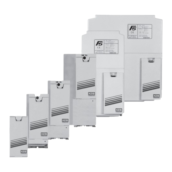
- Page 1 COMBIVERT Read Instruction manual part 1 first ! INSTRUCTION MANUAL Power Circuit 0.37...37 kW Mat. No. Rev. 00F50EB-K004...
- Page 3 GB - 3...
- Page 4 GB - 4...
-
Page 5: Table Of Contents
Table of Contents 1. General ..........................7 Preface ............................... 7 Validity and liability........................... 7 Copyright ............................8 1.4 Specified application ........................8 Product Description.......................... 8 Safety and operating instructions for drive converters .............. 10 1.7 Unit identification..........................11 Installation instructions ......................... 12 1.8.1 Cooling systems..........................12 1.8.2 Safety relay for „safety stop in accordance with EN954-1/ category 3“... - Page 6 Table of Contents GB - 6...
-
Page 7: General
Preface General Preface First we would like to welcome you as a customer of the company Karl E. Brinkmann GmbH and congratulation to the purchase of this product. You have decided for a product on highest technical niveau. The described hard- and software are developments of the Karl E. Brinkmann GmbH. The en- closed documents correspond to conditions valid at printing. -
Page 8: Copyright
The used semiconductors and components of KEB are developed and dimensioned for the use in industrial products. If the KEB COMBIVERT F5 is used in machines, which work under exceptional conditions or if essential functions, life-supporting measures or an extraordinary safety step must be fulfilled, the necessary reliability and security must be ensured by the ma- chine builder. - Page 9 Preface Features of the power circuits: • only slight switching losses due to IGBT • low noise development due to high switching frequency • extensive safety device for current, voltage and temperature • voltage and current monitoring in static and dynamic operation •...
-
Page 10: Safety And Operating Instructions For Drive Converters
Preface Safety and operating instructions for drive converters Safety and Operating Instructions for drive converters (in conformity with the Low-Voltage Directive 2006/95/EC) 1. General 4 Installation In operation, drive converters, depending on their degree of pro- The installation and cooling of the appliances shall be in accor- tection, may have live, uninsulated, and possibly also moving or dance with the specifications in the pertinent documentation. -
Page 11: Unit Identification
Preface 1.7 Unit identification 10 . F5 . C 1 B -3 A 0 A at frequency inverter: Cooling at servos: Motor cooling 0, 5, A, F Heat sink (standard) Self-cooling 1, B, G Flat rear External cooling 2, C, H Water-cooling system 3, D, I Convection... -
Page 12: Installation Instructions
• the power supply to the drive must be interrupted (double security) • no torque at the drive The KEB COMBIVERT F5 with safety relay fulfills the condition: no torque by a safe disconnec- tion of the driver signals for the power modules (IGBT). There is no voltage disconnection. -
Page 13: Control Cabinet Installation
Preface 1.8.3 Control cabinet installation Mounting distances Dimension Distance in mm Distance in inch 1) Distance to preceding elements in the cabinet door. Direction of the Front and side view of the coolant inlet cooling fins Coolant outlet Coolant inlet GB - 13... -
Page 14: Technical Data
Technical Data Technical Data Operating conditions Standard Standard/class Instructions EN 61800-2 Inverter-product standard: rated specifications Definition acc. EN 61800-5-1 Inverter-product standard: general safety max. 2000 m above sea level Site altitude With site altitudes over 1000 m a derating of 1 % per 100 m must be taken into consideration. -
Page 15: Technical Data Of The 230 V Class
The technical data are for 2- / 4-pole standard motors. With other pole numbers the inverter must be dimensioned onto the motor rated current. Contact KEB for special or medium frequency motors. Site altitude maximal 2000 m. With site altitudes over 1000 m a derating of 1 % per 100 m must be taken into con- sideration. - Page 16 The technical data are for 2- / 4-pole standard motors. With other pole numbers the inverter must be dimensioned onto the motor rated current. Contact KEB for special or medium frequency motors. Site altitude maximal 2000 m. With site altitudes over 1000 m a derating of 1 % per 100 m must be taken into consideration.
- Page 17 The technical data are for 2/4-pole standard motors. With other pole numbers the inverter must be dimensioned onto the motor rated current. Contact KEB for special or medium frequency motors. Site altitude maximal 2000 m. With site altitudes over 1000 m a derating of 1 % per 100 m must be taken into con- sideration.
-
Page 18: Technical Data Of The 400 V Class
The technical data are for 2/4-pole standard motors. With other pole numbers the inverter must be dimensioned onto the motor rated current. Contact KEB for special or medium frequency motors. Site altitude maximal 2000 m. With site altitudes over 1000 m a derating of 1 % per 100 m must be taken into con- sideration. - Page 19 The technical data are for 2/4-pole standard motors. With other pole numbers the inverter must be dimensioned onto the motor rated current. Contact KEB for special or medium frequency motors. Site altitude maximal 2000 m. With site altitudes over 1000 m a derating of 1 % per 100 m must be taken into con- sideration.
-
Page 20: Dc Supply
Technical data of the 400 V class DC supply The DC input current of the inverter is basically determined by the used motor. The data can be taken from the motor name plate. 230V class: √3 • motor rated voltage • motor rated current • motor cos φ ––––––––––––––––––––––––––––––––––––––––––––––––––––––––––––––––––––––––... -
Page 21: Dimensions And Weights
Technical Data - Dimensions and Weights Dimensions and Weights Ø F Ø F housing – – – – – – – – – * with submounted filter; C1 Operator housing Heat sink (standard) Heat sink with filter Flat rear Convection [kg] [kg] [kg]... -
Page 22: Terminal Strips Of The Power Circuit
Connection Terminals Terminal strips of the power circuit Attention! 230 V and 400 V-classes are possible All terminal strips meet the requirements on EN 60947-7-1 (IEC 60947-7-1) Housing size A Name Function Cable cross-section terminal no. U, V, W Motor side Line side Motor connection PA, PB... - Page 23 Connection Terminals Housing size G (without 15.200 V and 18.400 V) Name Function Cable cross-section terminal no. L1, L2, L3 3-phase mains connection U, V, W Motor connection ++, PB Connection for braking resistor ++, – – Connection for braking module, regenerating front T1 T2 end and supply units or DC voltage input 250…370 VDC (230 V class) 420…720 VDC (400 V class)
-
Page 24: Permissible Cable Cross-Sections And Tightening Torques Of The Terminals
Connection Terminals 2.5.1 Permissible cable cross-sections and tightening torques of the terminals permissible cross-section flexible with wire-end ferrule Tightening torque mm² AWG/MCM lb inch – – Screw M4 for ring thimble 20.5 2…4 3...5 – – Screw M4 for ring thimble GB - 24... -
Page 25: Connection Power Unit
3-ph. connection DC supply 250...370V DC (230V class) 420...720V DC (400V class) Legend Mains fuse Main contactor Mains choke Radio interference filter KEB COMBIVERT Motor choke or output filter (not at F5-M or F5-S) Motor Mounting plate GB - 25... - Page 26 Connection Power Unit External The function must be activated via the software of the control card (CP.28/Pn.12) in order temperature monitoring that an evaluation occurs at F5-B/C/G. Do not lay connection cable (also shielded) together with control cable ! F5-E/H/M/S: Thermostat relay Temperature sensor (PTC) In the motor cable, only per-...
-
Page 27: Annex A
Annex Annex A Overload characteristic Time [s] Characteristic 1 Load [%] 105 110 115 120 125 130 135 140 145 150 160 170 180 190 200 210 220 The characteristic declines device-dependently in this range (see unit identification). On exceeding a load of 105% the overload integrator starts. When falling below the integrator counts backwards. Error E.OL is triggered if the integrator achieves the inverter appropriate overload characteristic. -
Page 28: Protection In Accordance With Ul
Monthly Examine and clean extracted air filter and cooling air filter of the control cabinet. Examine function of the fans of the KEB COMBIVERT. The fans must be replaced in case of audible vibrations or squeak. Make a visual leak test of the cooling circuit for water-cooled inverters. -
Page 29: Shut Down
If the capacitor starts running with rated voltage, it is tried to build the oxide film abrupt again. This causes heat and gas and leads to the destruction of the capacitor. In order to avoid defectives, the KEB COMBIVERT must be started up depending on the storage period in accor- dance with the following specification: Storage period <... -
Page 30: Annex B
In this case the operator may need to take corresponding measures. B.1.2 UL Marking Acceptance according to UL is marked at KEB inverters with the adjacent logo on the type plate. To be conform according to UL for the use on the North American and Canadian Market the following instructions must be observed (original text of the UL): •... - Page 31 Notes GB - 31...
- Page 32 +49 5263 401-0 • fax: +49 5263 401-116 net: www.keb.de • mail: info@keb.de KEB worldwide… KEB Antriebstechnik Austria GmbH KEB (UK) Ltd. Ritzstraße 8 • A-4614 Marchtrenk 6 Chieftain Buisiness Park, Morris Close fon: +43 7243 53586-0 • fax: +43 7243 53586-21...
Need help?
Do you have a question about the Combivert F5 series and is the answer not in the manual?
Questions and answers