Table of Contents
Advertisement
Quick Links
Advertisement
Table of Contents

Related Manuals for AUMA SAEx 07.2-UW


Summary of Contents for AUMA SAEx 07.2-UW
- Page 1 Multi-turn actuators SAEx 07.2-UW SAEx 16.2-UW SAREx 07.2-UW SAREx 16.2-UW for continuous underwater use with actuator controls ACExC 01.2 Non-Intrusive Control Parallel Profibus DP Profinet Modbus RTU Modbus TCP/IP Foundation Fieldbus HART Operation instructions Assembly, operation, commissioning...
-
Page 2: Table Of Contents
This document contains information for assembly, commissioning and maintenance staff. Reference documents: Manual (Operation and setting) of actuator controls ACExC 01.2 Profibus DP Manual (Fieldbus device integration) of actuator controls ACExC 01.2 Profibus DP Reference documents are available on the Internet at: http://www.auma.com. Table of contents Page Safety instructions......................... - Page 3 8.1. Indications during commissioning 8.2. Indications in the display 8.2.1. Feedback signals from actuator and valve 8.2.2. Status indications according to AUMA classification 8.2.3. Status indications according to NAMUR recommendation 8.3. Indication lights of local controls Signals (output signals)......................9.1.
- Page 4 13.1. Technical data Multi-turn actuators 13.2. Technical data Actuator controls 13.3. Tightening torques for screws Spare parts..........................14.1. Multi-turn actuators SAEx 07.2-UW SAEx 16.2-UW/SAREx 07.2-UW SAREx 16.2-UW 14.2. Actuator controls ACExC 01.2 KT/KM 14.3. Actuator controls ACExC 01.2 KP/KPH 14.4.
-
Page 5: Safety Instructions
SAEx 07.2-UW SAEx 16.2-UW / SAREx 07.2-UW SAREx 16.2-UW Control unit: electronic (MWG) ACExC 01.2 Non-Intrusive Profibus DP Safety instructions Safety instructions 1.1. Prerequisites for the safe handling of the product The end user or the contractor must ensure that all legal requirements, directives,... -
Page 6: Range Of Application
1, 2, 21, and 22. If temperatures >40 °C are to be expected at the valve flange or the valve stem (e.g. due to hot media), please consult AUMA. Temperatures > 40 °C are not considered with regard to the non-electrical explosion protection. -
Page 7: Warnings And Notes
SAEx 07.2-UW SAEx 16.2-UW / SAREx 07.2-UW SAREx 16.2-UW Control unit: electronic (MWG) ACExC 01.2 Non-Intrusive Profibus DP Safety instructions 1.3. Warnings and notes The following warnings draw special attention to safety-relevant procedures in these operation instructions, each marked by the appropriate signal word (DANGER, WARNING, CAUTION, NOTICE). -
Page 8: Short Description
The AUMA Cloud is the driving element of the digital AUMA world, acting as interactive platform for efficient maintenance of AUMA actuators at moderate cost. The AUMA Cloud collects all device data of all actuators within one site and provides a clear overview at a glance. Detailed analysis provides valuable information on potential maintenance requirements. - Page 9 The AUMA Assistant App enables remote setting and remote diagnostics of AUMA AUMA Assistant App actuators via Bluetooth using either smartphone or tablet. The AUMA Assistant App can be downloaded free of charge from the Play Store (Android) or App Store (iOS). Figure 2: Link to AUMA Assistant App...
-
Page 10: Name Plate
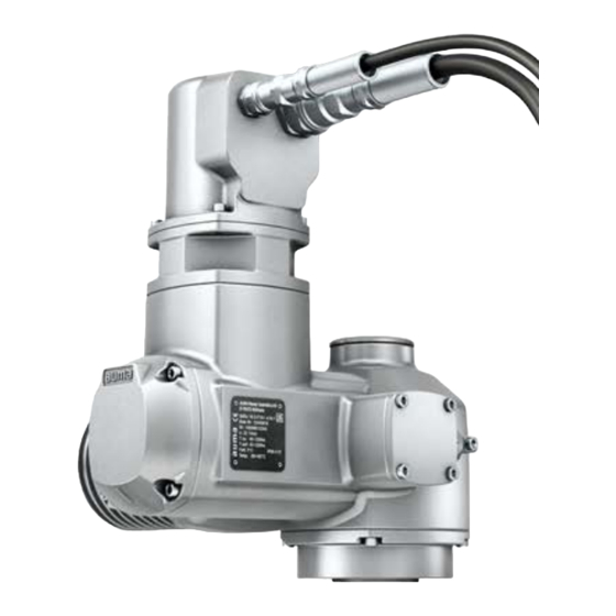
SAEx 07.2-UW SAEx 16.2-UW / SAREx 07.2-UW SAREx 16.2-UW Control unit: electronic (MWG) Name plate ACExC 01.2 Non-Intrusive Profibus DP Name plate Figure 3: Arrangement of name plates Actuator name plate Actuator controls name plate Motor name plate Additional plate, e.g. KKS plate (Power Plant Classification System) - Page 11 Figure 5: Actuator controls name plate (= manufacturer logo) Type designation Order number Serial number Actuator terminal plan Actuator controls terminal plan Mains voltage AUMA power class for switchgear Permissible ambient temperature Enclosure protection [10] Control [11] Data Matrix code Motor name plate Figure 6: Motor name plate (example) (= manufacturer logo);...
- Page 12 Threads for line bushings at electrical connection Not used Descriptions referring to name plate indications Type designation Table 1: Description of type designation actuator (in our example: SAEx 07.2-UW-F10) SAEx 07.2 -F10 SAEx Type SAEx = Multi-turn actuators for open-close duty Type SAREx = Multi-turn actuators for modulating duty 07.2...
- Page 13 The rated power (nominal power) of the actuator motor is indicated in kW on the motor name plate. For the assignment of the AUMA power classes to the nominal power of the motor types, refer to the separate electrical data sheets.
-
Page 14: Transport And Storage
Perform lift trial at low height to eliminate any potential danger e.g. by tilting. Figure 9: Example: Lifting the actuator Weights Table 6: Weights of multi-turn actuators SAEx 07.2-UW SAEx 16.2-UW / SAREx 07.2-UW SAREx 16.2- with 3-phase AC motors... -
Page 15: Storage
ADX... Refer to motor name plate Indicated weight includes AUMA NORM multi-turn actuator with 3-phase AC motor, electrical con- nection or plug/socket connector incl. cable glands (approx. 2.3 kg) as well as output drive type B1. For other output drive types, heed additional weights. Heed weight of cables if plug/socket connector is linked. -
Page 16: Assembly
SAEx 07.2-UW SAEx 16.2-UW / SAREx 07.2-UW SAREx 16.2-UW Control unit: electronic (MWG) Assembly ACExC 01.2 Non-Intrusive Profibus DP Assembly 5.1. Mounting position The product described in this document can be operated without restriction in any mounting position. 5.2. Mount actuator to valve Corrosion due to damage to paint finish and condensation! Touch up damage to paint finish after work on the device. -
Page 17: 5.2.1.1. Multi-Turn Actuator With Output Drive Type B: Mount
SAEx 07.2-UW SAEx 16.2-UW / SAREx 07.2-UW SAREx 16.2-UW Control unit: electronic (MWG) ACExC 01.2 Non-Intrusive Profibus DP Assembly 5.2.1.1. Multi-turn actuator with output drive type B: mount Figure 11: Mounting output drive types B Multi-turn actuator Valve/gearbox Valve/gearbox shaft Procedure Check if mounting flanges fit together. -
Page 18: Accessories For Assembly
SAEx 07.2-UW SAEx 16.2-UW / SAREx 07.2-UW SAREx 16.2-UW Control unit: electronic (MWG) Assembly ACExC 01.2 Non-Intrusive Profibus DP 5.3. Accessories for assembly 5.3.1. Handwheel temporarily mounted for setting tasks Figure 12: Version prepared for temporary handwheel operation (with protective cap) -
Page 19: Handwheel Permanently Mounted For Emergency Operation And Setting Tasks
SAEx 07.2-UW SAEx 16.2-UW / SAREx 07.2-UW SAREx 16.2-UW Control unit: electronic (MWG) ACExC 01.2 Non-Intrusive Profibus DP Assembly 5.3.2. Handwheel permanently mounted for emergency operation and setting tasks Figure 14: Version with permanently mounted handwheel (with bellows) For actuator in version with permanently mounted handwheel, the handwheel is provided for operation during setting tasks and for emergency operation of the actuator. -
Page 20: Electrical Connection
The pertaining wiring diagram/terminal plan (in German or English) is attached to the device in a weather-proof bag, together with these operation instructions. It can plan also be requested from AUMA (state order number, refer to name plate) or downloaded directly from the Internet (http://www.auma.com). Permissible networks The actuators are suitable for use in TN and TT networks with directly grounded star point for nominal voltages up to maximum 690 V AC. - Page 21 5.5 kW 63 A (g/R) I²t<5,000A²s The AUMA power class (A1, B1, ...) is indicated on the actuator controls name plate Consider the motor starting current (IA) (refer to electrical data sheet) when selecting the circuit breaker. We recommend tripping characteristics D or K for circuit breakers in accordance with IEC 60947-2.
- Page 22 SAEx 07.2-UW SAEx 16.2-UW / SAREx 07.2-UW SAREx 16.2-UW Control unit: electronic (MWG) Electrical connection ACExC 01.2 Non-Intrusive Profibus DP Fieldbus cable Table 11: Cable recommendation Only cables complying with IEC 61158 or IEC 61784, cable type A, may be used for Profibus DP wiring.
-
Page 23: Cable Installation Between Actuator Controls (Wall Bracket) And Actuator
The plant operator or the contractor are responsible for providing the required cable protection. The permissible cable length between actuator controls on wall bracket and the actuator amounts to 100 m maximum. Exclusively use AUMA “LSW” cable sets as connecting cables “LSW”! Table 12: Cable set LSW 81... - Page 24 SAEx 07.2-UW SAEx 16.2-UW / SAREx 07.2-UW SAREx 16.2-UW Control unit: electronic (MWG) Electrical connection ACExC 01.2 Non-Intrusive Profibus DP For LSW 82 cable set, the cover must be opened at wall bracket level and the cables must be connected to the terminals according to the terminal plan.
-
Page 25: Kt/Km Electrical Connection
SAEx 07.2-UW SAEx 16.2-UW / SAREx 07.2-UW SAREx 16.2-UW Control unit: electronic (MWG) ACExC 01.2 Non-Intrusive Profibus DP Electrical connection 6.3. KT/KM electrical connection Figure 20: KT/KM electrical connection Terminal carrier with screw-type/spring clamp terminals Connection frame Figure shows KT version... -
Page 26: Terminal Compartment: Open
SAEx 07.2-UW SAEx 16.2-UW / SAREx 07.2-UW SAREx 16.2-UW Control unit: electronic (MWG) Electrical connection ACExC 01.2 Non-Intrusive Profibus DP 6.3.1. Terminal compartment: open Figure 21: Open terminal compartment Cover (illustration shows KT version in type of protection Ex e) -
Page 27: Cable Connection
SAEx 07.2-UW SAEx 16.2-UW / SAREx 07.2-UW SAREx 16.2-UW Control unit: electronic (MWG) ACExC 01.2 Non-Intrusive Profibus DP Electrical connection 6.3.2. Cable connection Table 15: Terminal cross sections and tightening torques Designation Terminal cross sections Connection type Power contacts Flexible or solid:... - Page 28 SAEx 07.2-UW SAEx 16.2-UW / SAREx 07.2-UW SAREx 16.2-UW Control unit: electronic (MWG) Electrical connection ACExC 01.2 Non-Intrusive Profibus DP In case of a fault, electric shock due to presence of hazardous voltage if the PE conductor is NOT connected! Risk of death or serious injury! Connect all protective earth conductors.
-
Page 29: Fieldbus Cables: Connect
SAEx 07.2-UW SAEx 16.2-UW / SAREx 07.2-UW SAREx 16.2-UW Control unit: electronic (MWG) ACExC 01.2 Non-Intrusive Profibus DP Electrical connection 6.3.3. Fieldbus cables: connect 6.3.3.1. Fieldbus connection for line topology Figure 25: Line topology □ Channel 1: Further fieldbus devices follow ▣... - Page 30 SAEx 07.2-UW SAEx 16.2-UW / SAREx 07.2-UW SAREx 16.2-UW Control unit: electronic (MWG) Electrical connection ACExC 01.2 Non-Intrusive Profibus DP Connection with support terminals for line topology When using solid cables (single or multiple strands), additional support terminals must be used.The support terminals (terminal blocks) are mounted above the terminal carrier.
-
Page 31: Terminal Compartment: Close
SAEx 07.2-UW SAEx 16.2-UW / SAREx 07.2-UW SAREx 16.2-UW Control unit: electronic (MWG) ACExC 01.2 Non-Intrusive Profibus DP Electrical connection 6.3.4. Terminal compartment: close Figure 30: Close terminal compartment Cover (illustration shows KT version in type of protection Ex e) -
Page 32: Kp/Kph Electrical Connection
SAEx 07.2-UW SAEx 16.2-UW / SAREx 07.2-UW SAREx 16.2-UW Control unit: electronic (MWG) Electrical connection ACExC 01.2 Non-Intrusive Profibus DP 6.4. KP/KPH electrical connection Figure 31: KP and KPH electrical connection Screw-type terminals Plug-in frame (flameproof) Short description KP/KPH plug-in electrical connection with screw-type terminals for power and control contacts. -
Page 33: Terminal Compartment: Open
SAEx 07.2-UW SAEx 16.2-UW / SAREx 07.2-UW SAREx 16.2-UW Control unit: electronic (MWG) ACExC 01.2 Non-Intrusive Profibus DP Electrical connection 6.4.1. Terminal compartment: open Figure 32: Cover (figure shows KP version) Screws for cover O-ring Blanking plugs Cable gland (example) Flameproof frame The terminal compartment is designed in protection type Ex e (increased safety). -
Page 34: Cable Connection
SAEx 07.2-UW SAEx 16.2-UW / SAREx 07.2-UW SAREx 16.2-UW Control unit: electronic (MWG) Electrical connection ACExC 01.2 Non-Intrusive Profibus DP 6.4.2. Cable connection Table 17: Terminal cross sections and terminal tightening torques Designation Terminal cross sections Tightening torques Power contacts (U1, V1, W1) With small clamp washers: 1.1 Nm... -
Page 35: Fieldbus Cables: Connect
I or II) □ Channel 1: Further fieldbus devices will follow (standard) ▣ Channel 2: Further fieldbus devices will follow (AUMA redundancy I or II only) Last fieldbus device ■ Fieldbus cable from previous device (input) Fieldbus cable to next device (output) -
Page 36: Terminal Compartment: Close
SAEx 07.2-UW SAEx 16.2-UW / SAREx 07.2-UW SAREx 16.2-UW Control unit: electronic (MWG) Electrical connection ACExC 01.2 Non-Intrusive Profibus DP 6.4.4. Terminal compartment: close Figure 36: Close terminal compartment Cover (figure shows KP version) Screws for cover O-ring Blanking plugs... -
Page 37: Kes Electrical Connection
SAEx 07.2-UW SAEx 16.2-UW / SAREx 07.2-UW SAREx 16.2-UW Control unit: electronic (MWG) ACExC 01.2 Non-Intrusive Profibus DP Electrical connection 6.5. KES electrical connection Figure 37: KES electrical connection Terminal blocks Connection frame Short description KES plug-in electrical connection with terminal blocks for power and control contacts. -
Page 38: Terminal Compartment: Open
SAEx 07.2-UW SAEx 16.2-UW / SAREx 07.2-UW SAREx 16.2-UW Control unit: electronic (MWG) Electrical connection ACExC 01.2 Non-Intrusive Profibus DP 6.5.1. Terminal compartment: open Figure 38: Open terminal compartment Cover (illustration shows type of protection Ex e) Screws for cover... -
Page 39: Cable Connection
SAEx 07.2-UW SAEx 16.2-UW / SAREx 07.2-UW SAREx 16.2-UW Control unit: electronic (MWG) ACExC 01.2 Non-Intrusive Profibus DP Electrical connection 6.5.2. Cable connection Table 19: Terminal cross sections and terminal tightening torques Designation Terminal cross sections Tightening torques Power contacts (U, V, W) max. -
Page 40: Fieldbus Cables: Connect
I or II) □ Channel 1: Further fieldbus devices will follow (standard) ▣ Channel 2: Further fieldbus devices will follow (AUMA redundancy I or II only) Last fieldbus device ■ Fieldbus cable from previous device (input) Fieldbus cable to next device (output) -
Page 41: Terminal Compartment: Close
SAEx 07.2-UW SAEx 16.2-UW / SAREx 07.2-UW SAREx 16.2-UW Control unit: electronic (MWG) ACExC 01.2 Non-Intrusive Profibus DP Electrical connection 6.5.4. Terminal compartment: close Figure 42: Close terminal compartment Cover (illustration shows type of protection Ex e) Screws for cover... -
Page 42: Operation
SAEx 07.2-UW SAEx 16.2-UW / SAREx 07.2-UW SAREx 16.2-UW Control unit: electronic (MWG) Operation ACExC 01.2 Non-Intrusive Profibus DP Operation 7.1. Manual operation Actuators equipped with manual gearing can be operated via handwheel in manual operation. When switching on the motor, the manual drive will automatically be disengaged. -
Page 43: Motor Operation
SAEx 07.2-UW SAEx 16.2-UW / SAREx 07.2-UW SAREx 16.2-UW Control unit: electronic (MWG) ACExC 01.2 Non-Intrusive Profibus DP Operation 7.2. Motor operation Valve damage due to incorrect basic setting! Prior to electric actuator operation, perform the basic settings for “type of seating”... -
Page 44: Actuator Operation From Remote
SAEx 07.2-UW SAEx 16.2-UW / SAREx 07.2-UW SAREx 16.2-UW Control unit: electronic (MWG) Operation ACExC 01.2 Non-Intrusive Profibus DP 7.2.2. Actuator operation from remote Risk of immediate actuator operation when switching on! Risk of personal injuries or damage to the valve If the actuator starts unexpectedly: Immediately turn selector switch to 0 (OFF). -
Page 45: Menu Layout And Navigation
SAEx 07.2-UW SAEx 16.2-UW / SAREx 07.2-UW SAREx 16.2-UW Control unit: electronic (MWG) ACExC 01.2 Non-Intrusive Profibus DP Operation Table 20: Important push button functions for menu navigation Push buttons Navigation sup- Functions port on display Up ▲ Change screen/selection... -
Page 46: User Level, Password
SAEx 07.2-UW SAEx 16.2-UW / SAREx 07.2-UW SAREx 16.2-UW Control unit: electronic (MWG) Operation ACExC 01.2 Non-Intrusive Profibus DP the push buttons on the local controls have not been operated within 10 minutes or by briefly pressing C When entering the ID within the main menu, screens can be displayed directly (without Direct display via ID clicking through). -
Page 47: Password Entry
SAEx 07.2-UW SAEx 16.2-UW / SAREx 07.2-UW SAREx 16.2-UW Control unit: electronic (MWG) ACExC 01.2 Non-Intrusive Profibus DP Operation 7.4.1. Password entry Select desired menu and hold down push button for approx. 3 seconds. Display indicates the set user level, e.g Observer (1) Select higher user level via Up ▲... -
Page 48: Language In The Display
SAEx 07.2-UW SAEx 16.2-UW / SAREx 07.2-UW SAREx 16.2-UW Control unit: electronic (MWG) Operation ACExC 01.2 Non-Intrusive Profibus DP 7.5. Language in the display The display language can be selected. 7.5.1. Language change Display M0009 Language M0049 Set selector switch to position 0 (OFF). -
Page 49: Indications
If no entry is made over a longer period of time (approx. 1 minute), the display automatically returns to the first status indication. 8.2. Indications in the display Menus and functions depend on the actuator controls firmware version! Should menus or functions be unavailable, please contact the AUMA Service. -
Page 50: Feedback Signals From Actuator And Valve
SAEx 07.2-UW SAEx 16.2-UW / SAREx 07.2-UW SAREx 16.2-UW Control unit: electronic (MWG) Indications ACExC 01.2 Non-Intrusive Profibus DP The status bar (first row in the display) indicates the operation mode [1], the presence Status bar of an error [2] and the ID number [3] of the current display indication. - Page 51 SAEx 07.2-UW SAEx 16.2-UW / SAREx 07.2-UW SAREx 16.2-UW Control unit: electronic (MWG) ACExC 01.2 Non-Intrusive Profibus DP Indications The bar graph display appears after approx. 3 seconds. Figure 60: Torque allows to select the unit displayed (percent %, Newton metre Nm...
-
Page 52: Status Indications According To Auma Classification
Pause for operation in direction OPEN Pause for operation in directions OPEN and CLOSE 8.2.2. Status indications according to AUMA classification These indications are available if the parameter Diagnostic classific. M0539 is set to AUMA. Warnings (S0005) If a warning has occurred, the display shows S0005: the number of warnings occurred a blinking question mark after approx. -
Page 53: Status Indications According To Namur Recommendation
SAEx 07.2-UW SAEx 16.2-UW / SAREx 07.2-UW SAREx 16.2-UW Control unit: electronic (MWG) ACExC 01.2 Non-Intrusive Profibus DP Indications Not ready REMOTE (S0006) The S0006 display shows indications of the Not ready REMOTE group. If such an indication has occurred, the display shows S0006: the number of indications occurred a blinking crossbar after approx. - Page 54 SAEx 07.2-UW SAEx 16.2-UW / SAREx 07.2-UW SAREx 16.2-UW Control unit: electronic (MWG) Indications ACExC 01.2 Non-Intrusive Profibus DP Figure 69: Function check For further information, please also refer to <Corrective action>. Maintenance required (S0010) The S0010 indication shows maintenance indications according to NAMUR recommendation NE 107.
-
Page 55: Indication Lights Of Local Controls
SAEx 07.2-UW SAEx 16.2-UW / SAREx 07.2-UW SAREx 16.2-UW Control unit: electronic (MWG) ACExC 01.2 Non-Intrusive Profibus DP Indications 8.3. Indication lights of local controls Figure 72: Arrangement and signification of indication lights Marking with symbols (standard) Marking with figures 1... -
Page 56: Signals (Output Signals)
SAEx 07.2-UW SAEx 16.2-UW / SAREx 07.2-UW SAREx 16.2-UW Control unit: electronic (MWG) Signals (output signals) ACExC 01.2 Non-Intrusive Profibus DP Signals (output signals) 9.1. Signals via fieldbus Feedback signals via fieldbus can be configured. Configuration is possible for both data structure and data contents. -
Page 57: Analogue Signals (Analogue Outputs)
SAEx 07.2-UW SAEx 16.2-UW / SAREx 07.2-UW SAREx 16.2-UW Control unit: electronic (MWG) ACExC 01.2 Non-Intrusive Profibus DP Signals (output signals) 9.3. Analogue signals (analogue outputs) Analogue signals are only available if additional input signals are provided. Requirements Signal: E2 = 0/4... -
Page 58: Commissioning (Basic Settings)
SAEx 07.2-UW SAEx 16.2-UW / SAREx 07.2-UW SAREx 16.2-UW Control unit: electronic (MWG) Commissioning (basic settings) ACExC 01.2 Non-Intrusive Profibus DP Commissioning (basic settings) Set selector switch to position 0 (OFF). Information: The selector switch is not a mains switch. When positioned to 0 (OFF), the actuator cannot be operated. -
Page 59: Torque Switching: Set
SAEx 07.2-UW SAEx 16.2-UW / SAREx 07.2-UW SAREx 16.2-UW Control unit: electronic (MWG) ACExC 01.2 Non-Intrusive Profibus DP Commissioning (basic settings) Press Edit. Display indicates: ▶ Specialist (4) User login Up ▲ Down ▼ to select user: Information: Required user level: Specialist (4) or higher The symbols have the following meaning: black triangle: ▶... - Page 60 SAEx 07.2-UW SAEx 16.2-UW / SAREx 07.2-UW SAREx 16.2-UW Control unit: electronic (MWG) Commissioning (basic settings) ACExC 01.2 Non-Intrusive Profibus DP Up ▲ Down ▼ to select: CLOSE or OPEN ▶ Trip torque CLOSE ▶ Trip torque OPEN The black triangle ▶ indicates the current selection.
-
Page 61: Limit Switching: Set
SAEx 07.2-UW SAEx 16.2-UW / SAREx 07.2-UW SAREx 16.2-UW Control unit: electronic (MWG) ACExC 01.2 Non-Intrusive Profibus DP Commissioning (basic settings) 10.3. Limit switching: set Valve damage at valve/gearbox due to incorrect setting! When setting with motor operation: Stop actuator prior to reaching end of travel (press STOP push button). - Page 62 SAEx 07.2-UW SAEx 16.2-UW / SAREx 07.2-UW SAREx 16.2-UW Control unit: electronic (MWG) Commissioning (basic settings) ACExC 01.2 Non-Intrusive Profibus DP Set end position CLOSED again : Set end position CLOSED CMD0009with Information: The following description applies to actuators with handwheel.
-
Page 63: Test Run
SAEx 07.2-UW SAEx 16.2-UW / SAREx 07.2-UW SAREx 16.2-UW Control unit: electronic (MWG) ACExC 01.2 Non-Intrusive Profibus DP Commissioning (basic settings) 12. Make selection: Edit → back to step 9: Set end position CLOSED "once again" Esc → back to step 4; either set end position OPEN or exit the menu. -
Page 64: Direction Of Rotation: Check
SAEx 07.2-UW SAEx 16.2-UW / SAREx 07.2-UW SAREx 16.2-UW Control unit: electronic (MWG) Commissioning (basic settings) ACExC 01.2 Non-Intrusive Profibus DP 10.4.1. Direction of rotation: check Valve damage due to incorrect direction of rotation! If the direction of rotation is wrong, switch off immediately (press STOP). -
Page 65: Corrective Action
SAEx 07.2-UW SAEx 16.2-UW / SAREx 07.2-UW SAREx 16.2-UW Control unit: electronic (MWG) ACExC 01.2 Non-Intrusive Profibus DP Corrective action Corrective action 11.1. Faults during commissioning Table 23: Faults during operation/commissioning Fault Description/cause Remedy In spite of correct setting of mechan-... - Page 66 SAEx 07.2-UW SAEx 16.2-UW / SAREx 07.2-UW SAREx 16.2-UW Control unit: electronic (MWG) Corrective action ACExC 01.2 Non-Intrusive Profibus DP Table 25: Warnings and Out of specification Indication on display Description/cause Remedy Config. warning Collective signal 06: Press push button...
- Page 67 SAEx 07.2-UW SAEx 16.2-UW / SAREx 07.2-UW SAREx 16.2-UW Control unit: electronic (MWG) ACExC 01.2 Non-Intrusive Profibus DP Corrective action Warnings and Out of specification Indication on display Description/cause Remedy SIL fault SIL sub-assembly fault has occurred. Refer to separate Manual Functional Safety.
- Page 68 Selector switch is not in position REMOTE. Set selector switch to position REMOTE. Service active Operation via service interface (Bluetooth) and Exit service software. AUMA CDT service software. Disabled Actuator is in operation mode Disabled. Check setting and status of function <Local controls enable>.
-
Page 69: Fuses
SAEx 07.2-UW SAEx 16.2-UW / SAREx 07.2-UW SAREx 16.2-UW Control unit: electronic (MWG) ACExC 01.2 Non-Intrusive Profibus DP Corrective action Not ready REMOTE and Function check (collective signal 04) Indication on display Description/cause Remedy EMCY behav. active Operation mode EMERGENCY is active (EMER- Detect cause for EMERGENCY signal. -
Page 70: Fuse Replacement
SAEx 07.2-UW SAEx 16.2-UW / SAREx 07.2-UW SAREx 16.2-UW Control unit: electronic (MWG) Corrective action ACExC 01.2 Non-Intrusive Profibus DP 11.3.2. Fuse replacement 11.3.2.1. Replace fuses F1/F2 Information: Only valid for version with electrical connection of KES type, KT type or KL type Electric shock due to presence of hazardous voltage! Death or serious injury. -
Page 71: Motor Protection (Thermal Monitoring)
SAEx 07.2-UW SAEx 16.2-UW / SAREx 07.2-UW SAREx 16.2-UW Control unit: electronic (MWG) ACExC 01.2 Non-Intrusive Profibus DP Corrective action To replace defective fuses: Carefully loosen power supply unit [3] and pull out. (The fuses are on the equipped part of the power supply board.) Cable damage due to pinching! Risk of functional failures. -
Page 72: Servicing And Maintenance
Therefore, we recommend contacting our service. Only perform servicing and maintenance tasks when the device is switched off. AUMA AUMA offers extensive service such as servicing and maintenance as well as Service & Support customer product training. For the contact addresses, refer to our website (www.auma.com). -
Page 73: Disconnection From The Mains With Kt/Km Electrical Connection
SAEx 07.2-UW SAEx 16.2-UW / SAREx 07.2-UW SAREx 16.2-UW Control unit: electronic (MWG) ACExC 01.2 Non-Intrusive Profibus DP Servicing and maintenance 12.2.1. Disconnection from the mains with KT/KM electrical connection Figure 76: KT/KM electrical connection Cover Screws for cover O-ring... -
Page 74: Disconnection From The Mains With Kp/Kph And Kes Electrical Connection
Removing the plug: Remove electrical connection. Cover [1] and plug-in type frame [4] or connection frame [5] remain together. Seal open plug/socket connection, e.g. using AUMA protection cover and parking frame. Clean sealing faces of plug/socket connector and housing. Fitting the plug/socket connector: Preserve joint surfaces with an acid-free corrosion protection agent. -
Page 75: Disposal And Recycling
We recommend replacing the seals when changing the grease. After maintenance, perform leak tightness test at actuator and electrical connec- tions. The mobile PV 1691 leakage tester by AUMA can be used for leak tightness test. Perform visual inspection of actuator and mounted accessories. Ensure that Notes relating to main- no outside damage, changes or leakage of grease and oil are visible. - Page 76 SAEx 07.2-UW SAEx 16.2-UW / SAREx 07.2-UW SAREx 16.2-UW Control unit: electronic (MWG) Servicing and maintenance ACExC 01.2 Non-Intrusive Profibus DP Greases and oils are hazardous to water and must not be released into the environment. Arrange for controlled waste disposal of the disassembled material or for sep- arate recycling according to materials.
-
Page 77: Technical Data
Indication whether manual operation is active/not active via single switch (1 change-over contact) tion) Electrical connection The AUMA Ex plug/socket connector is part of the cable set with wall bracket which must be ordered separately and which is customised for connection. Terminal compartment additionally sealed against interior (double sealed) -
Page 78: Technical Data Actuator Controls
AUMA silver-grey (similar to RAL 7037) Option: Available colours on request Lifetime AUMA multi-turn actuators meet or exceed the lifetime requirements of EN 15714-2. Detailed information can be provided on request. Sound pressure level < 72 dB (A) Further information... - Page 79 The reversing contactors are designed for a lifetime of 2 million starts. For applications requiring a high number of starts, we recommend the use of thyristor units. For the assignment of AUMA power classes, please refer to electrical data on actuator. Control and feedback signals...
- Page 80 Enclosure protection in accordance IP68 with IEC 60529 According to AUMA definition, enclosure protection IP68 meets the following requirements: Depth of water: Maximum 8 m head of water Continuous immersion in water: maximal 96 hours For exact version, refer to actuator controls name plate.
-
Page 81: Tightening Torques For Screws
SAEx 07.2-UW SAEx 16.2-UW / SAREx 07.2-UW SAREx 16.2-UW Control unit: electronic (MWG) ACExC 01.2 Non-Intrusive Profibus DP Technical data 13.3. Tightening torques for screws Table 32: Tightening torques for screws Threads Tightening torque [Nm] Strength class A2-70/A4-70 A2-80/A4-80 1,015... -
Page 82: Spare Parts
SAEx 07.2-UW SAEx 16.2-UW / SAREx 07.2-UW SAREx 16.2-UW Control unit: electronic (MWG) Spare parts ACExC 01.2 Non-Intrusive Profibus DP Spare parts 14.1. Multi-turn actuators SAEx 07.2-UW SAEx 16.2-UW/SAREx 07.2-UW SAREx 16.2-UW... - Page 83 Spare parts Please state device type and our order number (see name plate) when ordering spare parts. Only original AUMA spare parts should be used. Failure to use original spare parts voids the warranty and exempts AUMA from any liability. Representation of spare parts may slightly vary from actual delivery.
-
Page 84: Actuator Controls Acexc 01.2 Kt/Km
SAEx 07.2-UW SAEx 16.2-UW / SAREx 07.2-UW SAREx 16.2-UW Control unit: electronic (MWG) Spare parts ACExC 01.2 Non-Intrusive Profibus DP 14.2. Actuator controls ACExC 01.2 KT/KM... - Page 85 Spare parts Please state device type and our order number (see name plate) when ordering spare parts. Only original AUMA spare parts should be used. Failure to use original spare parts voids the warranty and exempts AUMA from any liability. Representation of spare parts may slightly vary from actual delivery.
-
Page 86: Actuator Controls Acexc 01.2 Kp/Kph
SAEx 07.2-UW SAEx 16.2-UW / SAREx 07.2-UW SAREx 16.2-UW Control unit: electronic (MWG) Spare parts ACExC 01.2 Non-Intrusive Profibus DP 14.3. Actuator controls ACExC 01.2 KP/KPH... - Page 87 Spare parts Please state device type and our order number (see name plate) when ordering spare parts. Only original AUMA spare parts should be used. Failure to use original spare parts voids the warranty and exempts AUMA from any liability. Representation of spare parts may slightly vary from actual delivery.
-
Page 88: Actuator Controls Aumatic Acexc 01.2 Kes
SAEx 07.2-UW SAEx 16.2-UW / SAREx 07.2-UW SAREx 16.2-UW Control unit: electronic (MWG) Spare parts ACExC 01.2 Non-Intrusive Profibus DP 14.4. Actuator controls AUMATIC ACExC 01.2 KES... - Page 89 Spare parts Please state device type and our order number (see name plate) when ordering spare parts. Only original AUMA spare parts should be used. Failure to use original spare parts voids the warranty and exempts AUMA from any liability. Representation of spare parts may slightly vary from actual delivery.
-
Page 90: Exc Wall Bracket
SAEx 07.2-UW SAEx 16.2-UW / SAREx 07.2-UW SAREx 16.2-UW Control unit: electronic (MWG) Spare parts ACExC 01.2 Non-Intrusive Profibus DP 14.5. ExC wall bracket... - Page 91 Spare parts Please state device type and our order number (see name plate) when ordering spare parts. Only original AUMA spare parts should be used. Failure to use original spare parts voids the warranty and exempts AUMA from any liability. Representation of spare parts may slightly vary from actual delivery.
-
Page 92: Index
SAEx 07.2-UW SAEx 16.2-UW / SAREx 07.2-UW SAREx 16.2-UW Control unit: electronic (MWG) Index ACExC 01.2 Non-Intrusive Profibus DP Index Electrical connection Enclosure protection 10, 11, 13, 78, 80 Accessories for assembly Error - indication on display Actual value - indication on... - Page 93 SAEx 07.2-UW SAEx 16.2-UW / SAREx 07.2-UW SAREx 16.2-UW Control unit: electronic (MWG) ACExC 01.2 Non-Intrusive Profibus DP Index Main menu Range of application Mains voltage 11, 20 Rated voltage Maintenance 6, 72, 74 Recycling Maintenance required - indic- reductions...
- Page 94 SAEx 07.2-UW SAEx 16.2-UW / SAREx 07.2-UW SAREx 16.2-UW Control unit: electronic (MWG) Index ACExC 01.2 Non-Intrusive Profibus DP Wall bracket Warnings - indication on dis- play Wire diameter (fieldbus cable) Wiring diagram 13, 20 Year of production...
- Page 96 AUMA Riester GmbH & Co. KG P.O. Box 1362 DE 79373 Muellheim Tel +49 7631 809 - 0 Fax +49 7631 809 - 1250 info@auma.com www.auma.com Y009.518/003/en/1.21 For detailed information on AUMA products, refer to the Internet: www.auma.com...
Need help?
Do you have a question about the SAEx 07.2-UW and is the answer not in the manual?
Questions and answers