AUMA SAExC 07.1 Operation Instructions Manual
Electric multi-turn actuators with actuator controls for group i, category m2
Hide thumbs
Also See for SAExC 07.1:
- Operation instructions manual (76 pages) ,
- Operation instructions manual (88 pages)

Related Manuals for AUMA SAExC 07.1


Summary of Contents for AUMA SAExC 07.1
- Page 1 Electric multi-turn actuators SAExC 07.1 – SAExC 16.1 SARExC 07.1 – SARExC 16.1 with actuator controls AUMA MATIC AMExC 01.1 for group I, category M2 Operation instructions...
-
Page 2: Table Of Contents
Operation instructions These instructions valid for multi-turn actuators of the type range Scope of these instructions: SAExC 07.1 – SAExC 16.1/SARExC 07.1 – SARExC 16.1 with the actuator controls AMExC 01.1. These operation instructions are only valid for “clockwise closing”, i.e. - Page 3 Multi-turn actuators SAExC 07.1 – SAExC 16.1/ SARExC 07.1 – SARExC 16.1 Operation instructions with actuator controls AUMA MATIC AMExC 01.1 Page Setting the mechanical position indicator (option) Closing the switch compartment Actuator controls AUMA MATIC 20.1 Functions of the diagnosis LEDs on the interface board (standard version) 20.2...
-
Page 4: Safety Instructions
Multi-turn actuators SAExC 07.1 – SAExC 16.1/SARExC 07.1 – SARExC 16.1 with actuator controls AUMA MATIC AMExC 01.1 Operation instructions Safety instructions Range of application AUMA actuators are designed for the operation of industrial valves, e.g. globe valves, gate valves, butterfly valves and ball valves. -
Page 5: Short Description
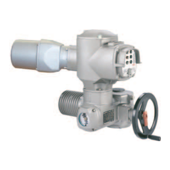
Multi-turn actuators SAExC 07.1 – SAExC 16.1/ SARExC 07.1 – SARExC 16.1 Operation instructions with actuator controls AUMA MATIC AMExC 01.1 Short description AUMA multi-turn actuators of the type range SAExC 07.1 – SAExC 16.1/SARExC 07.1 – SARExC 16.1 are driven by an electric motor and controlled by the actuator controls AUMA MATIC AMExC 01.1, which is included in the scope of delivery. -
Page 6: Technical Data
Multi-turn actuators SAExC 07.1 – SAExC 16.1/SARExC 07.1 – SARExC 16.1 with actuator controls AUMA MATIC AMExC 01.1 Operation instructions Technical data Features and functions Explosion protection Standard: IM2 Ex de or Ex de [ib] I IM2 c I Option:... - Page 7 Multi-turn actuators SAExC 07.1 – SAExC 16.1/ SARExC 07.1 – SARExC 16.1 Operation instructions with actuator controls AUMA MATIC AMExC 01.1 Rated power Refer to motor name plate Note: The controls is designed for the rated power of the actuator...
- Page 8 7) Cable length between actuator and AUMA MATIC max. 100 m. Not suitable for version with potentiometer in the actuator. Instead of the potentiometer, an RWG...
-
Page 9: Additional Information To The Wiring Diagram Legend
Multi-turn actuators SAExC 07.1 – SAExC 16.1/ SARExC 07.1 – SARExC 16.1 Operation instructions with actuator controls AUMA MATIC AMExC 01.1 Additional information to the wiring diagram legend Information A: A running indication is possible if blinker transmitter (S5) is installed (opening and closing of contacts). -
Page 10: Transport, Storage And Packaging
Multi-turn actuators SAExC 07.1 – SAExC 16.1/SARExC 07.1 – SARExC 16.1 with actuator controls AUMA MATIC AMExC 01.1 Operation instructions Transport, storage and packaging Transport For transport to place of installation, use sturdy packaging. Do not attach ropes or hooks to the handwheel for the purpose of lifting by hoist. -
Page 11: Mounting To Valve/Gearbox
Multi-turn actuators SAExC 07.1 – SAExC 16.1/ SARExC 07.1 – SARExC 16.1 Operation instructions with actuator controls AUMA MATIC AMExC 01.1 Mounting to valve/gearbox Prior to mounting the multi-turn actuator must be checked for damage. Damaged parts must be replaced by original spare parts. - Page 12 Multi-turn actuators SAExC 07.1 – SAExC 16.1/SARExC 07.1 – SARExC 16.1 with actuator controls AUMA MATIC AMExC 01.1 Operation instructions Finish machining of stem nut (output drive type A): Figure 5 Output drive type A Stem nut 80.3 80.01/80.02 80.2 The output drive flange does not have to be removed from the actuator.
-
Page 13: Mounting Positions Of The Local Controls
Multi-turn actuators SAExC 07.1 – SAExC 16.1/ SARExC 07.1 – SARExC 16.1 Operation instructions with actuator controls AUMA MATIC AMExC 01.1 Mounting positions of the local controls The mounting position of the local controls is designed according to the order. If, after mounting the actuator to the valve or the gearbox on site, the local controls is in an unfavourable condition, the mounting position can eas- ily be changed at a later date. -
Page 14: Electrical Connection
The wiring diagram applicable to the actuator is attached to the handwheel in a weather-proof bag, together with the operation instructions. In case the wiring diagram is not available, it can be obtained from AUMA (state com- mission no., refer to name plate) or downloaded directly from the Internet (www.auma.com). - Page 15 Multi-turn actuators SAExC 07.1 – SAExC 16.1/ SARExC 07.1 – SARExC 16.1 Operation instructions with actuator controls AUMA MATIC AMExC 01.1 Heater As standard, the control unit of the actuator is equipped with a heater to pre- vent condensation within the actuator. Unless ordered otherwise, the heater is internally supplied.
-
Page 16: Connection With Ex-Plug-In Terminal Connection (Kes)
Multi-turn actuators SAExC 07.1 – SAExC 16.1/SARExC 07.1 – SARExC 16.1 with actuator controls AUMA MATIC AMExC 01.1 Operation instructions Connection with Ex-plug-in terminal connection (KES) Before mains connection: Check whether type of current, supply voltage, Figure 11: Connection and frequency correspond to motor data (refer to name plate at motor). -
Page 17: Manual Operation
Multi-turn actuators SAExC 07.1 – SAExC 16.1/ SARExC 07.1 – SARExC 16.1 Operation instructions with actuator controls AUMA MATIC AMExC 01.1 Manual operation The actuator may be operated manually for purposes of setting and com- missioning and in case of motor failure or power failure. -
Page 18: Operation And Indications Of The Local Controls
Multi-turn actuators SAExC 07.1 – SAExC 16.1/SARExC 07.1 – SARExC 16.1 with actuator controls AUMA MATIC AMExC 01.1 Operation instructions 10. Operation and indications of the local controls Figure 18: Local controls Push buttons Indication lights Selector switch Selector switch... - Page 19 Multi-turn actuators SAExC 07.1 – SAExC 16.1/ SARExC 07.1 – SARExC 16.1 Operation instructions with actuator controls AUMA MATIC AMExC 01.1 Push buttons If the selector switch is in position local control (I), use the push buttons OPEN - STOP - CLOSE to operate the actuator locally.
-
Page 20: Opening The Switch Compartment
Multi-turn actuators SAExC 07.1 – SAExC 16.1/SARExC 07.1 – SARExC 16.1 with actuator controls AUMA MATIC AMExC 01.1 Operation instructions 11. Opening the switch compartment To be able to carry out the following settings (up to and including clause 18.), the switch compartment must be opened and, if installed, the indicator disc must be removed. -
Page 21: Setting The Limit Switching
Multi-turn actuators SAExC 07.1 – SAExC 16.1/ SARExC 07.1 – SARExC 16.1 Operation instructions with actuator controls AUMA MATIC AMExC 01.1 12. Setting the limit switching 12.1 Setting end position CLOSED (black section) Turn handwheel clockwise until valve is closed. -
Page 22: Setting The Duo Limit Switching (Option)
Multi-turn actuators SAExC 07.1 – SAExC 16.1/SARExC 07.1 – SARExC 16.1 with actuator controls AUMA MATIC AMExC 01.1 Operation instructions 13. Setting the DUO limit switching (option) Any application can be switched on or off via the two intermediate position switches. -
Page 23: Setting The Torque Switching
Multi-turn actuators SAExC 07.1 – SAExC 16.1/ SARExC 07.1 – SARExC 16.1 Operation instructions with actuator controls AUMA MATIC AMExC 01.1 14. Setting the torque switching 14.1 Setting The set torque must suit the valve! This setting must only be changed with the consent of the... -
Page 24: Test Run
Multi-turn actuators SAExC 07.1 – SAExC 16.1/SARExC 07.1 – SARExC 16.1 with actuator controls AUMA MATIC AMExC 01.1 Operation instructions 15. Test run Work at the open actuator under voltage must only be performed if it is assured that for the duration of the work there is no danger of explosion. -
Page 25: Checking The Setting Of The Limit Switching
Multi-turn actuators SAExC 07.1 – SAExC 16.1/ SARExC 07.1 – SARExC 16.1 Operation instructions with actuator controls AUMA MATIC AMExC 01.1 15.2 Checking the setting of the limit switching Set selector switch to position OFF (0) (figure 30). Figure 30: Selector switch OFF The controls’... -
Page 26: Setting The Potentiometer (Option)
Multi-turn actuators SAExC 07.1 – SAExC 16.1/SARExC 07.1 – SARExC 16.1 with actuator controls AUMA MATIC AMExC 01.1 Operation instructions 16. Setting the potentiometer (option) — For remote indication — Move valve to end position CLOSED. Turn potentiometer (E2) clockwise to the stop. -
Page 27: Setting The Electronic Position Transmitter Rwg (Option)
Multi-turn actuators SAExC 07.1 – SAExC 16.1/ SARExC 07.1 – SARExC 16.1 Operation instructions with actuator controls AUMA MATIC AMExC 01.1 17. Setting the electronic position transmitter RWG (option) — For remote indication or external control — After mounting the actuator on the valve, check setting and adjust, if neces- sary (refer to subclauses 17.1 or 17.2). -
Page 28: Setting 2-Wire System 4 - 20 Ma And 3-/4-Wire System 0 - 20 Ma
Multi-turn actuators SAExC 07.1 – SAExC 16.1/SARExC 07.1 – SARExC 16.1 with actuator controls AUMA MATIC AMExC 01.1 Operation instructions 17.1 Setting 2-wire system 4 – 20 mA and 3-/4-wire system 0 – 20 mA Connect voltage to electronic position transmitter. -
Page 29: Setting 3-/4- Wire System 4 - 20 Ma
Multi-turn actuators SAExC 07.1 – SAExC 16.1/ SARExC 07.1 – SARExC 16.1 Operation instructions with actuator controls AUMA MATIC AMExC 01.1 17.2 Setting 3-/4- wire system 4 – 20 mA Connect voltage to electronic position transmitter. Move valve to end position CLOSED. -
Page 30: Setting The Mechanical Position Indicator (Option)
Multi-turn actuators SAExC 07.1 – SAExC 16.1/SARExC 07.1 – SARExC 16.1 with actuator controls AUMA MATIC AMExC 01.1 Operation instructions 18. Setting the mechanical position indicator (option) Place indicator disc on shaft. Move valve to end position CLOSED. Turn lower indicator disc (figure 37) until symbol CLOSED is in align- ment with the mark on the cover (figure 38). -
Page 31: Actuator Controls Auma Matic
Multi-turn actuators SAExC 07.1 – SAExC 16.1/ SARExC 07.1 – SARExC 16.1 Operation instructions with actuator controls AUMA MATIC AMExC 01.1 20. Actuator controls AUMA MATIC During all work at the controls observe: Work at the open actuator under voltage must only be performed if it is assured that for the duration of the work there is no danger of explosion. -
Page 32: Programming The Logic Board
Multi-turn actuators SAExC 07.1 – SAExC 16.1/SARExC 07.1 – SARExC 16.1 with actuator controls AUMA MATIC AMExC 01.1 Operation instructions 20.2 Programming the logic board The type of seating – limit or torque seating – (switch S1-2 and switch S3-2, figure 41) must be determined by the valve manufacturer. -
Page 33: Emergency - Open And Emergency - Close Signal (Option)
Multi-turn actuators SAExC 07.1 – SAExC 16.1/ SARExC 07.1 – SARExC 16.1 Operation instructions with actuator controls AUMA MATIC AMExC 01.1 20.3 EMERGENCY - OPEN and EMERGENCY - CLOSE signal (option) digit in wiring diagram MSP … C, D, or P) -
Page 34: Electronic Positioner (Option)
Multi-turn actuators SAExC 07.1 – SAExC 16.1/SARExC 07.1 – SARExC 16.1 with actuator controls AUMA MATIC AMExC 01.1 Operation instructions 21. Electronic positioner (option) 21.1 Technical data Table 5: Technical data for positioner Command signal (input signal E1, set value) 0/4 –... -
Page 35: Setting Type Of Signal (Option)
Multi-turn actuators SAExC 07.1 – SAExC 16.1/ SARExC 07.1 – SARExC 16.1 Operation instructions with actuator controls AUMA MATIC AMExC 01.1 Figure 44: Positioner board A7 P9 (DE) S2-7 P7 (Sens) S3-7 P3 (0) P4 (max) Meas. points: MP2(+) MP1(–) Meas. -
Page 36: Setting Actuator Behaviour On Loss Of Signal
Multi-turn actuators SAExC 07.1 – SAExC 16.1/SARExC 07.1 – SARExC 16.1 with actuator controls AUMA MATIC AMExC 01.1 Operation instructions 21.2.2 Setting actuator behaviour on loss of signal In case of a loss of signal of nominal value E1 or actual value E2, the reac- tion of the actuator can be programmed via the switch S2-7. -
Page 37: Positioner Adjustment For End Position Closed (Standard Version)
Multi-turn actuators SAExC 07.1 – SAExC 16.1/ SARExC 07.1 – SARExC 16.1 Operation instructions with actuator controls AUMA MATIC AMExC 01.1 21.3 Positioner adjustment for end position CLOSED (standard version) Before beginning the setting of the positioner, it has to be ensured that the limit and torque switching of the actuator as well as the feedback have been set (clauses 16. -
Page 38: Positioner Adjustment For End Position Open (Standard Version)
Multi-turn actuators SAExC 07.1 – SAExC 16.1/SARExC 07.1 – SARExC 16.1 with actuator controls AUMA MATIC AMExC 01.1 Operation instructions 21.4 Positioner adjustment for end position OPEN (standard version) Run multi-turn actuator by pressing push button (local controls) to end position OPEN. - Page 39 Multi-turn actuators SAExC 07.1 – SAExC 16.1/ SARExC 07.1 – SARExC 16.1 Operation instructions with actuator controls AUMA MATIC AMExC 01.1 Figure 46: Cover plate for positioner Label with signal indication (in our example: E1 = 4 – 20 mA, E2 = 4 – 20 mA)
-
Page 40: Positioner Adjustment For End Position Open (Inverse Operation)
Multi-turn actuators SAExC 07.1 – SAExC 16.1/SARExC 07.1 – SARExC 16.1 with actuator controls AUMA MATIC AMExC 01.1 Operation instructions 21.6 Positioner adjustment for end position OPEN (inverse operation) In standard version the maximum input signal (E1 = 20 mA) results in opera- tion to end position OPEN. -
Page 41: Positioner Adjustment End Position Closed (Inverse Operation)
Multi-turn actuators SAExC 07.1 – SAExC 16.1/ SARExC 07.1 – SARExC 16.1 Operation instructions with actuator controls AUMA MATIC AMExC 01.1 21.7 Positioner adjustment end position CLOSED (inverse operation) Run actuator with push button (local controls) to end position CLOSED. -
Page 42: Positioner In Split Range Version (Option)
Multi-turn actuators SAExC 07.1 – SAExC 16.1/SARExC 07.1 – SARExC 16.1 with actuator controls AUMA MATIC AMExC 01.1 Operation instructions 21.8 Positioner in Split Range version (option) For Split Range, a modified version of the positioner is used. The standard version is not suitable for Split Range operation. - Page 43 Multi-turn actuators SAExC 07.1 – SAExC 16.1/ SARExC 07.1 – SARExC 16.1 Operation instructions with actuator controls AUMA MATIC AMExC 01.1 Figure 49: Positioner board A7, Split Range version P9 (DE) P7 (Sens) S2-7 P3 (0) P4 (max) S3-7 Meas. points...
-
Page 44: Timer (Option)
Multi-turn actuators SAExC 07.1 – SAExC 16.1/SARExC 07.1 – SARExC 16.1 with actuator controls AUMA MATIC AMExC 01.1 Operation instructions 22. Timer (option) The timer board is used to increase the operating time for the entire or any portion of the valve travel. -
Page 45: Setting Start And End Of Stepping Mode Via Duo Limit Switching (Option)
Multi-turn actuators SAExC 07.1 – SAExC 16.1/ SARExC 07.1 – SARExC 16.1 Operation instructions with actuator controls AUMA MATIC AMExC 01.1 22.2 Setting start and end of stepping mode via DUO limit switching (option) Start and end of stepping mode can also be set via external switches (use potential-free contacts). -
Page 46: Setting On And Off Times
Multi-turn actuators SAExC 07.1 – SAExC 16.1/SARExC 07.1 – SARExC 16.1 with actuator controls AUMA MATIC AMExC 01.1 Operation instructions 22.3 Setting ON and OFF times ON and OFF times can be set independently of each other between 1 – 30 seconds at the 4 potentiometers R10 to R13. -
Page 47: Fuses
Multi-turn actuators SAExC 07.1 – SAExC 16.1/ SARExC 07.1 – SARExC 16.1 Operation instructions with actuator controls AUMA MATIC AMExC 01.1 23. Fuses Flameproof enclosure! Before opening, ensure that no explosive gas and no voltage is present. When replacing fuses, only fuses according to table 13 may be used. -
Page 48: Motor Protection
Multi-turn actuators SAExC 07.1 – SAExC 16.1/SARExC 07.1 – SARExC 16.1 with actuator controls AUMA MATIC AMExC 01.1 Operation instructions 23.2 Motor protection In order to protect against overheating and impermissibly high temperatures at the actuator, PTC thermistors or thermoswitches are embedded in the motor winding. -
Page 49: Enclosure Protection Ip 68 (Option)
Multi-turn actuators SAExC 07.1 – SAExC 16.1/ SARExC 07.1 – SARExC 16.1 Operation instructions with actuator controls AUMA MATIC AMExC 01.1 24. Enclosure protection IP 68 (option) Definition According to EN 60 529, the conditions for meeting the requirements of enclosure protection IP 68 are to be agreed between manufacturer and user. -
Page 50: Maintenance
Multi-turn actuators SAExC 07.1 – SAExC 16.1/SARExC 07.1 – SARExC 16.1 with actuator controls AUMA MATIC AMExC 01.1 Operation instructions 25. Maintenance Regular inspection and maintenance (min. 3 year intervals) performed by qualified and trained personnel according to the European standard EN 60079-17 “Inspection and Main- tenance of Electrical Installations in Hazardous Areas”... -
Page 51: Lubrication
Multi-turn actuators SAExC 07.1 – SAExC 16.1/ SARExC 07.1 – SARExC 16.1 Operation instructions with actuator controls AUMA MATIC AMExC 01.1 We recommend additionally: If rarely operated, perform a test run about every 6 months. This ensures that the actuator is always ready to operate. -
Page 52: Spare Parts List Multi-Turn Actuator Saexc/Sarexc 07.1 - Saexc/Sarexc
Multi-turn actuators SAExC 07.1 – SAExC 16.1/SARExC 07.1 – SARExC 16.1 with actuator controls AUMA MATIC AMExC 01.1 Operation instructions 29. Spare parts list multi-turn actuator SAExC/SARExC 07.1 – SAExC/SARExC 16.1... - Page 53 Please state type and commission no. of the device (see name plate) when ordering spare parts. Only original AUMA spare parts should be used. Failure to use original spare parts voids the warranty and exempts AUMA from any lia- bility. Delivered spare parts may slightly vary from the representation.
-
Page 54: Spare Parts List Controls Amexc 01.1 With Terminal Connection (Kes)
Multi-turn actuators SAExC 07.1 – SAExC 16.1/SARExC 07.1 – SARExC 16.1 with actuator controls AUMA MATIC AMExC 01.1 Operation instructions 30. Spare parts list controls AMExC 01.1 with terminal connection (KES) - Page 55 Please state type and commission no. of the device (see name plate) when ordering spare parts. Only original AUMA spare parts should be used. Failure to use original spare parts voids the warranty and exempts AUMA from any lia- bility. Delivered spare parts may slightly vary from the representation.
-
Page 56: Exam Certificates
Multi-turn actuators SAExC 07.1 – SAExC 16.1/SARExC 07.1 – SARExC 16.1 with actuator controls AUMA MATIC AMExC 01.1 Operation instructions 31. EXAM certificates... - Page 57 Multi-turn actuators SAExC 07.1 – SAExC 16.1/ SARExC 07.1 – SARExC 16.1 Operation instructions with actuator controls AUMA MATIC AMExC 01.1...
- Page 58 Multi-turn actuators SAExC 07.1 – SAExC 16.1/SARExC 07.1 – SARExC 16.1 with actuator controls AUMA MATIC AMExC 01.1 Operation instructions...
- Page 59 Multi-turn actuators SAExC 07.1 – SAExC 16.1/ SARExC 07.1 – SARExC 16.1 Operation instructions with actuator controls AUMA MATIC AMExC 01.1...
- Page 60 Multi-turn actuators SAExC 07.1 – SAExC 16.1/SARExC 07.1 – SARExC 16.1 with actuator controls AUMA MATIC AMExC 01.1 Operation instructions...
- Page 61 Multi-turn actuators SAExC 07.1 – SAExC 16.1/ SARExC 07.1 – SARExC 16.1 Operation instructions with actuator controls AUMA MATIC AMExC 01.1...
-
Page 62: Declaration Of Conformity And Declaration Of Incorporation
Multi-turn actuators SAExC 07.1 – SAExC 16.1/SARExC 07.1 – SARExC 16.1 with actuator controls AUMA MATIC AMExC 01.1 Operation instructions 32. Declaration of Conformity and Declaration of Incorporation... -
Page 63: Index
Multi-turn actuators SAExC 07.1 – SAExC 16.1/ SARExC 07.1 – SARExC 16.1 Operation instructions with actuator controls AUMA MATIC AMExC 01.1 Index Ambient temperature Limit switching 21,22,25 Safety instructions Local controls Selector switch Logic board Self-retaining 19,32 Blinker transmitter Loss of signal... -
Page 64: Addresses
+49 7631 - 809-0 +49 711 - 34803 0 +49 7631 - 809 1250 +49 711 - 34803 34 riester@auma.com riester@wof.auma.com Certificate Registration No. 12 100/104 4269 www.auma.com www.auma.com For detailed information on AUMA products refer to the Internet: www.auma.com Y004.603/003/en/1.08 www.auma.com...
Need help?
Do you have a question about the SAExC 07.1 and is the answer not in the manual?
Questions and answers