Sign In
Upload
Download
Table of Contents
Contents
Add to my manuals
Delete from my manuals
Share
URL of this page:
HTML Link:
Bookmark this page
Add
Manual will be automatically added to "My Manuals"
Print this page
×
Bookmark added
×
Added to my manuals
Manuals
Brands
AUMA Manuals
Controller
SAVEx Series
Operation instructions manual
AUMA SAVEx Series Operation Instructions Manual
Multi-turn actuators
Hide thumbs
1
Table Of Contents
2
3
4
5
6
7
8
9
10
11
12
13
14
15
16
17
18
19
20
21
22
23
24
25
26
27
28
29
30
31
32
33
34
35
36
37
38
39
40
41
42
43
44
45
46
47
48
49
50
51
52
53
54
55
56
57
58
59
60
61
62
63
64
65
66
67
68
69
70
71
72
73
74
75
76
77
78
79
80
81
82
83
84
85
86
87
88
89
90
91
92
93
94
95
96
97
98
99
100
101
102
103
104
105
106
107
108
109
110
111
112
page
of
112
Go
/
112
Contents
Table of Contents
Bookmarks
Table of Contents
Table of Contents
1 Safety Instructions
Basic Information on Safety
Range of Application
Warnings and Notes
References and Symbols
2 Identification
Name Plate
Short Description
3 Transport, Storage and Packaging
Transport
Storage
Packaging
4 Assembly
Mounting Position
Handwheel Fitting
Multi-Turn Actuator: Mount to Valve/Gearbox
Output Drive Type a
4.3.1.1. Stem Nut: Finish Machining
4.3.1.2. Multi-Turn Actuator (with Output Drive Type A): Mount to Valve
Output Drive Types B
4.3.2.1. Multi-Turn Actuator with Output Drive Types B: Mount to Valve/Gearbox
Accessories for Assembly
Stem Protection Tube for Rising Valve Stem
Mounting Positions of Local Controls
Mounting Positions: Modify
5 Electrical Connection
Basic Information
KP/KPH Electrical Connection
Terminal Compartment: Open
Cable Connection
Fieldbus Cables: Connect
Terminal Compartment: Close
KES Electrical Connection
Terminal Compartment: Open
Cable Connection
Fieldbus Cables: Connect
Terminal Compartment: Close
KT/KM Electrical Connection
Terminal Compartment: Open
Cable Connection
Fieldbus Cables: Connect
Terminal Compartment: Close
External Earth Connection
Accessories for Electrical Connection
Actuator Controls on Wall Bracket
Parking Frame
Operation
Manual Operation
Engage Manual Operation
Manual Operation: Disengage
Motor Operation
Local Actuator Operation
Actuator Operation from Remote
Menu Navigation Via Push Buttons (for Settings and Indications)
Menu Layout and Navigation
User Level, Password
Password Entry
Password Change
Language in the Display
Language Change
Indications
Indications During Commissioning
Indications in the Display
Feedback Indications from Actuator and Valve
Status Indications According to AUMA Classification
Status Indications According to NAMUR Recommendation
Indication Lights of Local Controls
Optional Indications
Mechanical Position Indication Via Indicator Mark
Mechanical Position Indication (Self-Adjusting)
Signals (Output Signals)
Status Signals Via Output Contacts (Digital Outputs)
Assignment of Outputs
Coding the Outputs
Analogue Signals (Analogue Outputs)
Commissioning (Basic Settings)
Type of Seating: Set
Torque Switching: Set
Limit Switching: Set
Output Speed (Internal): Set
Fieldbus Address (Slave Address), Baud Rate, Parity and Monitoring Time: Set
Test Run
Direction of Rotation at Mechanical Position Indicator: Check
Direction of Rotation at Hollow Shaft/Stem: Check
Limit Switching: Check
Commissioning (Settings/Options in the Actuator)
Switch Compartment: Open/Close
Mechanical Position Indicator (Self-Adjusting)
Mechanical Position Indicator: Set
Gear Stage of the Reduction Gearing: Test/Set
Mechanical Position Indication Via Indicator Mark (Not Self-Adjusting)
Mechanical Position Indicator: Set
Gear Stage of the Reduction Gearing: Test/Set
Corrective Action
Faults During Operation/Commissioning
Fault Indications and Warning Indications
Signal "Motor Protection Tripped" (Via TMS Device)
Fuses
Fuses Within the Actuator Controls
Motor Protection (Thermal Monitoring)
Servicing and Maintenance
Preventive Measures for Servicing and Safe Operation
Disconnection from the Mains
Disconnection from the Mains with KP/KPH and KES Electrical Connection
Disconnection from the Mains with KT/KM Electrical Connection
Maintenance
Disposal and Recycling
Technical Data
Technical Data Multi-Turn Actuators
Technical Data Actuator Controls
Spare Parts
Multi-Turn Actuators Savex
Savex 16.2/Sarvex 07.2
Acvexc 01.2 KP/KPH Actuator Controls
Acvexc 01.2 KES Actuator Controls
Acvexc 01.2 KT/KM Actuator Controls
Certificates
Declaration of Incorporation and EU Declaration of Conformity
Index
Addresses
Advertisement
Quick Links
1
Electrical Connection
2
Basic Information
Download this manual
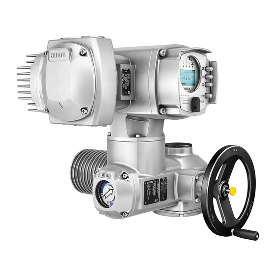
Multi-turn actuators
SAVEx 07.2
SAVEx 16.2
SARVEx 07.2
SARVEx 16.2
Control unit: electronic (MWG)
with actuator controls
ACVExC 01.2 Non-Intrusive
Control
Parallel
Profibus DP
Modbus RTU
Modbus TCP/IP
Foundation Fieldbus
HART
Operation instructions
Assembly, operation, commissioning
Table of
Contents
Previous
Page
Next
Page
1
2
3
4
5
Advertisement
Table of Contents
Need help?
Do you have a question about the SAVEx Series and is the answer not in the manual?
Ask a question
Questions and answers
Related Manuals for AUMA SAVEx Series
Control Systems AUMA ACV 01.2 Manual
Actuator controls (168 pages)
Controller AUMA ACVExC 01.2 Series Operation And Setting Manual
Actuator controls (144 pages)
Industrial Equipment AUMA SAVEx 07.2 Manual
Multi-turn actuators (116 pages)
Controller AUMA SAVEx 07.2 Operation Instructions Manual
Multi-turn actuators (116 pages)
Controller AUMA SAVEx 07.2 Operation Instructions Manual
Multi-turn actuators (100 pages)
Controller AUMA SAVEx 07.2 Operation Instructions Manual
Multi-turn actuators (100 pages)
Control Systems AUMA AC(V) 01.2 Manual
Actuator controls; profibus dp (92 pages)
Controller AUMA SA 07.2 Manual
Multi-turn actuators with actuator controls sfc version (24 pages)
Controller AUMA SA 07.2 Assembly Instructions
Square head for pit application (3 pages)
Controller AUMA SAV 07.2 Operation Instructions Manual
Multi-turn actuators (96 pages)
Controller AUMA SAV 07.2 Operation Instructions Manual
Multi-turn actuators control unit: electronic (mwg) with actuator controls acv 01.2 non-intrusive multiport valve version (92 pages)
Controller AUMA SAV Series Operation Instructions Manual
Multi-turn actuators (92 pages)
Controller AUMA SAV 07.6 Assembly Instructions
Square head for pit application (3 pages)
Controller AUMA SAV 10.2 Assembly Instructions
Square head for pit application (3 pages)
Controller AUMA SAV 14.2 Assembly Instructions
Square head for pit application (3 pages)
Controller AUMA SAEx Series Operation Instructions Manual
Multi-turn actuators, control unit: electronic (mwg) with actuator controls, acexc 01.2 non-intrusive (104 pages)
This manual is also suitable for:
Sarvex series
Savex 07.2
Savex 07.6
Savex 10.2
Savex 14.2
Savex 14.6
...
Show all
Savex 16.2
Sarvex 07.2
Sarvex 07.6
Sarvex 10.2
Sarvex 14.2
Sarvex 14.6
Sarvex 16.2
Save 07.2/ady 23 series
Sarve 07.2 series
Save 07.6/ady 24 series
Sarve 07.6 series
Save 10.2/ady 28 series
Sarve 10.2 series
Save 14.2/ady 51 series
Sarve 14.2 series
Save 14.6/ady 56 series
Sarve 14.6 series
Save 16.2/ady 82 series
Sarve 16.2 series
Acvexc 01.2
Table of Contents
Print
Rename the bookmark
Delete bookmark?
Delete from my manuals?
Login
Sign In
OR
Sign in with Facebook
Sign in with Google
Upload manual
Upload from disk
Upload from URL


Need help?
Do you have a question about the SAVEx Series and is the answer not in the manual?
Questions and answers