
Related Manuals for Novatech Bitronics M87X Series


Summary of Contents for Novatech Bitronics M87X Series
- Page 1 M87X SERIES MEASUREMENT SYSTEM Monitoring and Recording IED Manual August 15, 2018 ML0021 Document Revision R © 2018 by Bitronics, LLC...
-
Page 3: Table Of Contents
TABLE OF CONTENTS FIRMWARE VERSION ............................. vii M87x MANUAL SET ............................ix INSTALLATION AND MAINTENANCE ......................x WARRANTY AND ASSISTANCE ........................x AUTHORIZED REPRESENTATIVE IN THE EUROPEAN UNION ..............xi COPYRIGHT NOTICE ............................xi ... - Page 4 4.5 Energy (1-Cycle Update) ........................36 4.6 Frequency (1-Cycle Update) ......................... 37 4.7 Demand Measurements (1-Second Update) ..................37 4.7.1 Ampere and Fundamental Ampere Demand ................. 38 4.7.2 Volt Demand ..........................38 4.7.3 Power Demands (Total Watts, VARs, and VAs) ................39 ...
- Page 5 5.4.5 IEEE Long File Naming Convention ....................63 5.4.6 Voltage Fluctuation Table (VFT) File ....................65 5.4.7 Sequence of Events (SOE) File ...................... 67 5.4.8 Sequence of Events Recorder (SER) File ..................67 5.5 M87x File System ..........................68 ...
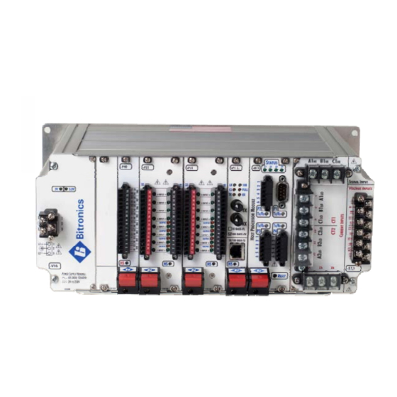
- Page 6 6.3.2 Physical ............................84 6.4 Power Supply and Protective Ground (Earth) Connections ..............85 6.5 Overcurrent Protection .......................... 85 6.6 Supply/Mains Disconnect ........................85 7.0 SIGNAL INPUT MODULE S10 - S12, S1C (M871), S13 - S17, S2C (M872) .......... 86 7.1 Introduction ............................
- Page 7 9.10.6 Disassembly of the P33 Module ....................129 9.10.7 Digital Output Board (803) Jumper Settings ................129 10.0 TRANSDUCER INPUT MODULE P40 ....................131 10.1 Introduction ............................131 10.2 Features ............................132 10.3 Specifications ............................ 133 ...
-
Page 8: Firmware Version
FIRMWARE VERSION The following table provides the most recent firmware and software versions. For best results, the Configurator version used should match with the firmware version. A complete list of firmware and software versions is provided on the 70 Series Utilities CD. NOTE: Host firmware versions 3.0x require 70 Series IEDs with 64 MB SDRAM. - Page 9 Firmware Versions Bios Host Utilities Release Description Version Firmware Firmware Configurator Date M87x Product Release: Added 1mHz accuracy on M87x. Improved poll rate to 100ms for a single P40 transducer inputs module. Fault distance configuration is changed. Time sync with respect to DNP master is changed from the DNP master jamming the time to asking the master what time to jam.
-
Page 10: M87X Manual Set
Firmware Versions Bios Host Utilities Release Description Version Firmware Firmware Configurator Date M87x Product Release: Support 1.35 M871 4.16 4.16 4.16 8/29/17 for S2C split core option 1.36 M872 1.35 M871 Maintenance Upgrade 4.17 4.17 4.17 4/5/18 1.36 M872 Windows XP Support for 1.35 M871 4.17 4.18... -
Page 11: Installation And Maintenance
CERTIFICATION Bitronics LLC certifies that the calibration of our products is based on measurements using equipment whose calibration is traceable to the United States National Institute of Standards Technology (NIST). INSTALLATION AND MAINTENANCE Bitronics LLC products are designed for ease of installation and maintenance. As with any product of this nature, installation and maintenance can present electrical hazards and should be performed only by properly trained and qualified personnel. -
Page 12: Authorized Representative In The European Union
AUTHORIZED REPRESENTATIVE IN THE EUROPEAN UNION NovaTech Europe BVBA Kontichsesteenweg 71 2630 Aartselaar Belgium T +32.3.458.0807 F +32.3.458.1817 info.europe@novatechweb.com COPYRIGHT NOTICE This manual is copyrighted and all rights are reserved. The distribution and sale of this manual is intended for the use of the original purchaser or his agents. This document may... - Page 13 The following are trademarks or registered trademarks of Systems Integration Specialists Company, Inc. (SISCO): SISCO MMS-EASE Lite AX-S4MMS The following are trademarks or registered trademarks of General Software, Inc.: General Software the GS logo EMBEDDED BIOS Embedded DOS The following are trademarks or registered trademarks of the PCI Industrial Computer Manufacturers Group: CompactPCI PICMG...
-
Page 14: Safety Section
SAFETY SECTION This Safety Section should be read before commencing any work on the equipment. Health and safety The information in the Safety Section of the product documentation is intended to ensure that products are properly installed and handled in order to maintain them in a safe condition. - Page 15 Voltage and current connections should be made using insulated crimp terminations to ensure that terminal block insulation requirements are maintained for safety. To ensure that wires are correctly terminated, the correct crimp terminal and tool for the wire size should be used. Before energizing the equipment, it must be grounded (earthed) using the protective ground (earth) terminal, or the appropriate termination of the supply plug in the case of plug connected equipment.
- Page 16 installing the Power Supply Module (Vxx) or the Signal Input Module (S1x). All connections to a module must be removed before removing the module. Do not attempt to install a module with signals connected. Fiber optic communication Where fiber optic communication devices are fitted, these should not be viewed directly. Optical power meters should be used to determine the operation or signal level of the device.
-
Page 17: Description
1.0 DESCRIPTION 1.1 Introduction The M87x family of monitoring and recording IEDs with SubCycle technology is a major breakthrough in power measurement technology. The M87x IEDs were designed to expand the limits of range, speed, and accuracy of measurement, speed of communications, and modularity. - Page 18 (Refer to Section 7 on Signal input modules) Input Signals (S10, S11, S12, S1C) CT Current Configuration 4 Inputs. 3 Phase Currents and 1 Neutral. Inputs (S10) Nominal 5Aac Peak Current Linear to 100A symmetrical (141A peak) at all rated temperatures. Overload 30Aac continuous.
- Page 19 Input Signals (S10, S11, S12, S1C) Frequency 15-70Hz VT (PT) AC Configuration 8 Inputs, Measures 2 Buses, 3 or 4 Wire. Voltage Inputs Nominal 120Vac (S10, S11, System Voltage Intended for use on nominal system voltages up to 480V rms phase-to-phase (277V rms S12) Terminals phase-to-neutral).
- Page 20 Input Signals (S13, S14, S15, S16, S17, S2C) CT Current Configuration 6 Inputs. 2 sets of 3 Phase Currents Inputs (S14) Nominal 1Aac/5Aac Peak Current Linear to 20A symmetrical (28A peak) at all rated temperatures. Overload 30Aac continuous. Withstands 400Aac for 2 seconds. Isolation 2500Vac, minimum.
- Page 21 Input Signals (S13, S14, S15, S16, S17, S2C) Burden 0.0016VA @ 1Arms, 60Hz (0.0016ohms @ 60Hz). Configuration 6 Inputs. 3 Phase Currents from 2 Lines with different peak current ranges. CT Current Configuration 6 Inputs. 2 sets of 3 Phase Currents Inputs (S2C);...
- Page 22 Voltage AC: Better than 0.1% of reading (20 to 425V rms, input-to-case). DC (AUX Inputs): +/- 0.2V (24 to 250Vdc, input-to-case) Current (S10, S13, Better than 0.1% of reading +/- 500μA (0.5A to 100.0A), S16 bus 2) Better than 0.1% of reading +/- 1mA (0.05A to 0.5A). Current (S11, S14, Better than 0.1% of reading +/- 100μA (0.5A to 20.0A), S16 bus 1, S17 bus...
- Page 23 Physical Connections Current (S10, Terminal block with 10-32 Studs for current inputs. Use ring lugs sized for #10 stud. (Signal Input S11, S12) Accepts #10-16 AWG (5.3-1.3mm ) wire. Recommended Torque: 16 In-Lbs, 1.81 N-m. Modules) Current inputs are connected to the output from the secondary of permanently installed Current Transformers (CTs).
- Page 24 -P40 Transducer Input Module Inputs 8 bi-directional, jumper selectable for voltage or current range. 0 – 10V Voltage Range Overload Range: -12.5 V to +12.5 Vdc Resolution: 0.381 mV Input Resistance: 10KΩ 0 – 1mA Current Range Overload Range: -2.5 mA to +2.5 mA Resolution: 0.0763 μA Input Resistance:...
- Page 25 Definitions: Installation Category (Overvoltage Category) III: Distribution Level, fixed installation, with smaller transient overvoltages than those at the primary supply level, overhead lines, cable systems, etc. Pollution: Any degree of foreign matter, solid, liquid, or gaseous that can result in a reduction of electric strength or surface resistivity of the insulation.
-
Page 26: Standards And Certifications
1.4 Standards and Certifications 1.4.1 Revenue Accuracy The M87x exceeds the accuracy requirements of ANSI C12.20 and IEC 60687. The accuracy class of the instrument to each standard is determined by the selected Signal Input Module. Module Nominal Certification Current S10, S13, S1C, ANSI C12.20, 0.5CA S16 bus 2... - Page 27 CSA C22.2 NO. 61010-2-030-12-CAN/CSA, Edition 1, Issue Date 2012/05/01, SAFETY REQUIREMENTS FOR ELECTRICAL EQUIPMENT FOR MEASUREMENT, CONTROL, AND LABORATORY USE - PART 2-030: PARTICULAR REQUIREMENTS FOR TESTING AND MEASURING CIRCUITS. If applicable, the CE mark must be prominently marked on the case label. ...
- Page 28 Group 1, Class A Frequency: 30 - 1000 MHz EN 55011 is applicable for the following EMC product and generic standards: IEC/EN 60255-26: 2013 + AC: 2013 (supercedes IEC/EN 60255-25: 2000, EN 61000-6-4: 2007 + A1:2011 (IEC date 2010) AC Powerline Conducted Emissions (Applicable on VT inputs - Bus1/ Bus 2 and AUX PWR (Universal Hi Range AC/DC Power supply) Basic EMC emissions standard (AC powerline conducted emissions):...
- Page 29 Electrical Fast Transient / Burst Immunity EN 61000-4-4: 2012 (supersedes EN 61000-4-4: 2004 + A1:2010, which superceded IEC61000-4-4: 1995) Burst Frequency: 5 kHz Amplitude, Input AC Power Ports: Severity Level 4; Amplitude ± 4 kV Amplitude, Signal Ports: Severity Level 3; Amplitude ± 2 kV Amplitude, Telecom Ports (Ethernet): ±...
- Page 30 biphenyls (PBB), polybrominated diphenyl ethers (PBDE), and 0.01% for cadmium, or qualify for an exemption to the limits as defined in Annex III or Annex IV of the RoHS Directive. Bitronics LLC certifies that the object(s) of declaration meet(s) the material requirements of the RoHS Directive 2011/65/EU, except where an exemption is allowed by the Directive.
-
Page 31: Housing And Backplane
2.0 HOUSING AND BACKPLANE The M87x chassis is a modular-by-board design, with a rugged aluminum housing specifically designed to meet the harsh conditions found in utility and industrial applications. The chassis features a passive backplane, an embedded and fully compatible CompactPCI (cPCI) bus section and proprietary signal input and analog (DSP) processor sections. - Page 32 Figure 2 - Mounting and Overall Dimensions (C07A5) ML0021 August 15, 2018 Copyright 2018 Bitronics, LLC...
- Page 33 13.45" (342) ø 0.25" 2.33" (59) 5.20" (132) 2.33" (59) 0.27" (6.9) 0.23" (5.7) 13.00" (330) Figure 3 - Mounting and Overall Dimensions (C12A8 and C10A7) ML0021 August 15, 2018 Copyright 2018 Bitronics, LLC...
-
Page 34: Installation
2.1 Installation WARNING - INSTALLATION AND MAINTENANCE SHOULD ONLY BE PERFORMED BY PROPERLY TRAINED OR QUALIFIED PERSONNEL. 2.2 Initial Inspection Bitronics instruments are carefully checked and "burned in" at the factory before shipment. Damage can occur however, so please check the instrument for shipping damage as it is unpacked. -
Page 35: Removal And Installation Of Modules
2.7 Removal and Installation of Modules All active circuitry is located on removable modules. Hot Swap modules may be installed and removed under power. Refer to the appropriate section or manual to determine if the particular module is Hot Swap compatible. For all other modules, remove all power from the unit before installing or removing any module. -
Page 36: Host / Analog-Digital Signal Processor Module H11/H12 And A10
3.0 HOST / ANALOG-DIGITAL SIGNAL PROCESSOR MODULE H11/H12 AND A10 The Host/Analog-Digital Signal Processor Module is an assembly consisting of two sections: the Host board and the Analog-Digital Signal Processor board. 3.1 Host board The Host CPU module consists of a 486-class microprocessor, four communications ports and a CompactPCI master bridge. -
Page 37: Standard Serial Ports (P2, P3, P4)
ip - Set Internet Protocol (IP) address information in "dotted decimal" format. The IP address defaults to "192.168.0.254". subnet – Set the Subnet mask. The Subnet mask defaults to "255.255.255.0". router – Set the Gateway (Router) address. The Gateway (Router) address defaults to "192.168.0.1". -
Page 38: Diagnostic Status Led's (S1, S2, S3, S4)
snapping the ferrite closed. Tie RS-485 cable shields (pin 5) to earth ground at one point in system. The recommended torque rating for the terminal block wire fasteners on ports P2-P4 is 2.2 In-Lbs, 0.25 N-m. 3.1.1c Diagnostic Status LED’s (S1, S2, S3, S4) There are four LED’s on the front panel: S1, S2, S3, and S4. - Page 39 Type the command "connect 01" (use the actual address assigned) to establish communications with the device in Zmodem protocol using RS485. This command will not be echoed back as you type it. After striking the enter key, the device will return a command prompt (for example c:\>, e:\data>, c:\config>, etc.) Once communications are established, you can now use the command-line interface, exactly as you would with a direct RS232 connection, to control the device (services supported by Zmodem protocol...
- Page 40 Figure 3 - Typical RS-232 & IRIG-B Cable Wiring ML0021 August 15, 2018 Copyright 2018 Bitronics, LLC...
- Page 41 Figure 4 – M870D RS-232 Cable Wiring Please note that the M870D detached display has been replaced by the D650 display ML0021 August 15, 2018 Copyright 2018 Bitronics, LLC...
- Page 42 Figure 4B - Typical RS-232 Wiring for D650 Display ML0021 August 15, 2018 Copyright 2018 Bitronics, LLC...
- Page 43 Figure 5 - Typical RS-485 Cable Wiring Please note that the M870D detached display has been replaced by the D650 display ML0021 August 15, 2018 Copyright 2018 Bitronics, LLC...
- Page 44 Figure 5B - Typical RS-485 Cable Wiring D650 Display and AOC ML0021 August 15, 2018 Copyright 2018 Bitronics, LLC...
- Page 45 ML0021 August 15, 2018 Copyright 2018 Bitronics, LLC...
- Page 46 Figure 6 - Host Port Signal Assignment ML0021 August 15, 2018 Copyright 2018 Bitronics, LLC...
-
Page 47: Self-Test Modes
3.1.2 Self-Test Modes The M87x has several self-tests built in to assure that the instrument is performing accurately. Refer to the appropriate protocol manual for details on how to retrieve the self-test information. The following table lists possible faults that would be detected by the self-tests, how the fault is indicated, the effects of the fault and any necessary corrective actions. -
Page 48: System Clock
3.1.3 System Clock The M87x has an internal System Clock with a capacitor backed RAM (typical data retention of 7 days at room temperature) when no power is applied to the unit. The clock is located on the Host board. The time settings may be changed via the Serial Port (P1) or various communication protocols. -
Page 49: Measurements
4.0 MEASUREMENTS Basic measurement quantities are calculated and updated every 1/4 cycle. These quantities include RMS Amperes and RMS Volts. Watts, VARs, VAs, Power Factor, all harmonic-based measurements (such fundamental-only quantities), Energy, Frequency, and Phase Angle are updated every cycle. Note: For all of the following measurements, it is important to keep in mind that the specific protocol used to access the data may affect the data that is available, or the format of that data. -
Page 50: Power Factor (1-Cycle Update)
are sampled simultaneously (including currents), these signals can be easily combined to form true Phase-to-Phase and Phase-to-Neutral differential measurements with extremely low amplitude and phase errors. It also allows accurate calculation of Bus-to-Bus differential voltages and angles. Each sample is corrected for offset and gain using factory calibration values stored in non-volatile memory on the board. -
Page 51: Geometric Va Calculations
In any connection type, the Total Watts and Total VARs is the arithmetic sum of the per- element Watts and VARs. The sign conventions are shown in Figure 7 (pg. 33). When used on 2-element systems, the reference phase voltage (typically phase B) input, is connected to the Neutral voltage input, and effectively causes one of the elements to be zero. -
Page 52: Equivalent Va Calculations
There is also a relationship to the Total Power Factor, which is described in Section 4.3. Total Power Factor calculations using the Arithmetic VA method will still indicate a "1" on a system with phase amplitude imbalance, but not with canceling leading and lagging loads. For example, on a system with a lagging load on one phase and an equal leading load on another phase, the value of the Arithmetic VAs will not change relative to a balanced system, but the Total Power Factor will be less than "1". -
Page 53: Frequency (1-Cycle Update)
4.6 Frequency (1-Cycle Update) Frequency is calculated every cycle for every input but the Auxiliary Voltages. The M87x monitors the change in Phase Angle per unit time using the Phase Angle measurement for the fundamental generated by the FFT. The System Frequency is the frequency of the input used for synchronizing the sampling rate (Section 3.2.2). -
Page 54: Ampere And Fundamental Ampere Demand
the traditional value of T is 15 minutes, although the M87x can accommodate other demand intervals (Section 4.7.7). The M87x generates a demand value using modern microprocessor technology in place of heating and cooling circuits, it is therefore much more accurate and repeatable over a wide range of input values. -
Page 55: Power Demands (Total Watts, Vars, And Vas)
4.7.3 Power Demands (Total Watts, VARs, and VAs) Present Total Watt, VAR, and VA Demands are calculated via the instantaneous measurement data. The Total VA Demand calculation type is based on the instantaneous Total VA calculation type (Section 4.4) Upon power-up, all Present Total Watt, VAR, and VA Demands are reset to the average of the stored Maximum and Minimum values. -
Page 56: Harmonic Measurements (1-Cycle Update)
32-bit number, some protocols may place further restrictions on the Demand Interval due to limitations on numerical format. Please refer to the appropriate protocol manual for details. 4.8 Harmonic Measurements (1-Cycle Update) M87x instruments continually sample all inputs at 128 samples per cycle, and compute a 128-point Fast Fourier Transform (FFT) every cycle for each input. -
Page 57: Fundamental Current (1-Cycle Update)
100 Amp load (if the Denominator was set at 100 Amps). In the M87x, Current Demand Distortion is implemented using Equation 3. The TDD equation is similar to Harmonic Distortion (Equation 2), except that the denominator in the equation is a user-defined number. -
Page 58: Fundamental Watts / Volt-Amperes (Vas) / Vars (1-Cycle Update)
(which is the denominator), and the result will be the actual RMS magnitude of the selected harmonic. Fundamental Volts and Amps can be used in conjunction to obtain Fundamental VAs, and when used with Displacement Power Factor can yield Fundamental Watts and Fundamental VARs. -
Page 59: Resistance, Reactance, Impedance (1-Cycle Update)
4.8.10 Resistance, Reactance, Impedance (1-Cycle Update) These measurements are calculated for each phase from the fundamental values of voltage and current. The Impedance value, combined with the voltage-to-current phase angle, gives the polar form of the impedance. The Resistance and Reactance represent the rectangular form of the Impedance. -
Page 60: Flicker
The current unbalance is calculated similarly using the current components. 100% 4.12 Flicker Flicker measurements are measured and evaluated according to IEC61000-4-15. Specific settings for Flicker are found on the “Flicker” page (previously named "Power Quality" tab) of the Configurator. The Nominal System Frequency should be selected appropriately for the system in the ”Instrument Transformer Ratio”... -
Page 61: Soelog Output
Fault Type: One point representing the fault type is available on Mx71 (Two points on Mx72 models). The user is able to select Fault Type if it is of interest when creating a user-configurable point list. The index number will be determined by where the point falls within the point list. - Page 62 analysis calculations and the peak fault current. The following measurements have been added: Measurement Modbus DNP3 Fault Type Bus 1 Modbus register DNP Analog Input Fault Distance XAN1 Modbus register DNP Analog Input Fault Distance XBN1 Modbus register DNP Analog Input Fault Distance XCN1 Modbus register DNP Analog Input...
-
Page 63: List Of Available Measurements
4.14 List of Available Measurements Please note that not all measurements are available in every M87x model (i.e. neutral current in M871 only, second set of current measurements and corresponding power, energy, etc. only in M872) Available Measurements Accrued Digital IO Module #0-6, Input 1-16 K-factor Amps B (1 and 2) Accrued Digital IO Module #0-6, Output 1-8 K-factor Amps C (1 and 2) - Page 64 Available Measurements Demand Volts Bus2 AN, BN, CN, AB, BC, CA Slip Freq. Volts A Bus1-Bus2 Demand Watts A, B, C, Total Slip Freq. Volts B Bus1-Bus2 Digital IO Module #0-6 Debounce Time Slip Freq. Volts C Bus1-Bus2 Digital IO Module #0-6 Input Point 1-16 SNTP Time Sync Digital IO Module #0-6 Output Point 1-8 Symmetrical comp.
- Page 65 Available Measurements Harmonic, Individual, Bus1, Volts A (1...63) Volts Aux1-Gnd, Aux2-Gnd, Aux1-Aux2 Harmonic, Individual, Bus1, Volts AB (1...63) Volts Bus1 AN, BN, CN, NG, AB, BC, CA Harmonic, Individual, Bus1, Volts B (1...63) Volts Bus2 AN, BN, CN, NG, AB, BC, CA Harmonic, Individual, Bus1, Volts BC (1...63) Watt-Hrs Normal (1 and 2) Harmonic, Individual, Bus1, Volts C (1...63)
-
Page 66: Functional Description
5.0 FUNCTIONAL DESCRIPTION 5.1 Passwords The M87x has implemented the standard Bitronics password scheme. There are three different access levels: Level 0: This access level provides read-only access to all settings and data, thus preventing modification of information that affects system security. The factory default password for level 0 is “AAAA”;... - Page 67 will appear in grey indicating the IEC61850 IED Configurator is the active tool. Only the 70 Series Configurator allows the user to select which configurator tool loads the IP and SNTP addresses. The configuration files are stored in the M87x directory c:\Config. The 70 Series Configurator will generate the IED Capability Description (ICD) file and automatically store it on the M87x in directory c:\Config.
-
Page 68: Triggering
5.3 Triggering Triggers can be configured in the 70 Series to initiate several different actions: Waveform Recorders Disturbance Recorders Digital Outputs Virtual Outputs SOE Entries Resetting of various measurements (Demands, Energy, etc.) Up to 120 triggers can be specified, of the following types: 5.3.1 Threshold Trigger Any measurement can be used to trigger a Waveform Recorder or Disturbance Recorder, or create an entry in the SOE log. - Page 69 Configuration of Hysteresis Settings For example: Suppose an alarm contact is intended to close when the frequency exceeds 60.3 Hz. Frequency is generally regulated very tightly about 60 Hz, so except for the significant transients that the setting is intended to capture, it would not be unusual for the frequency to dwell for a prolonged time near 60.3 Hz, fluctuating by only an insignificant amount but crossing the threshold many times (see illustration below, on the right half of the trace).
-
Page 70: Digital Input Trigger
Hysteresis may be used to constrain chatter in any of the Actions listed on the Recorder Triggers page (i.e. recorders, contacts, GOOSE messages, SOE Log entries, etc.) It may also be combined with a setting in the “Min Duration (ms)” column to prevent triggering on short-duration transients when a trigger might only be desired in connection with steady- state events;... -
Page 71: Manual Trigger
5.3.4 Manual Trigger Refer to the appropriate protocol manual for information. Manual Triggers may also be activated through BiView using Telnet, Zmodem, or under Modbus or DNP3 protocols (depending on what register set/ point list is chosen). When a manual trigger is initiated, it bypasses the standard trigger setup, and directly initiates the action specified by that command. -
Page 72: Periodic Triggers
Here, the first three conditions are logically “anded” together to drive Virtual Output 2. VO2, in turn, is configured to initiate a fault distance calculation on B1. Line to line fault distances are calculated when more than one of the A1, B1, C1 events are triggered. 5.3.8 Periodic Triggers Four independent periodic triggers are available that can be used to initiate all of the actions listed in section 5.3 above. -
Page 73: Recording
point will transition from 0 to 1 at the timers scheduled activation. It will hold at 1 briefly and then return to 0. These 'Periodic Trigger' points can then be used to trigger any of the actions selected. 5.4 Recording The M87x has five different methods of recording data. - Page 74 user. If additional triggers occur within the post-trigger period, the waveform record will be extended for the selected number of post-trigger cycles. Optionally, the user can choose to disable re-triggering. There is a limit of 2000 cycles (approximately 33.3 seconds at 60Hz) for each waveform record.
-
Page 75: Default Frequency Setting For Waveform Recorder
that selecting the 256 sample per cycle sampling rate disables all measurements associated with bus 2 voltages (Volts A2, B2, and C2) and auxiliary voltages (Volts Aux1- Gnd, Aux2-Gnd, and AuxDiff). Because the sampling rate is synchronized with the system frequency, the sample rate (in samples per second) will vary with frequency. -
Page 76: Retrieving And Deleting Waveform Recorder Files
power is removed from the M87x, the relay will revert to the default state. Assigning the digital outputs to indicate that a waveform record has been created must be performed by using the 70 Series Configurator. See Section 9 for information concerning output "Normally Open"... -
Page 77: Indicating Disturbance Records With Digital Outputs
Please note how the convention for determining time resolution in oscillography records (WR1, WR2) in samples per cycle is not relevant to long-time disturbance records (DR2, DR2), where RMS values are plotted using a sample rate measured in an integer number of cycles for each sample. -
Page 78: Trend Recorder
5.4.3 Trend Recorder The M87x stores the values of a user-configurable set of up to 230 parameters every log interval. The default setting of this interval is 0 minutes, which disables the Trend Recorder. This interval can be changed from 1 to 720 minutes (12 hrs.) in 1-minute increments. -
Page 79: Comtrade Zip Files
Retriever software programs. These are user-selectable binary or ASCII format files. The files are stored as compressed .zip files to increase storage and decrease user download times. These files may be retrieved and deleted from the instrument using the available communications protocols. - Page 80 When the long filename feature is enabled, the Disturbance Recorder and Waveform Recorder functions of the IED will create IEEE C37.232-2007 compatible names for all generated Comtrade files. Note, that in all cases the IED compresses and stores Comtrade files within a Zip file. Generation of Comtrade files for the Trend Recorder function is handled by the BiView software application.
-
Page 81: Voltage Fluctuation Table (Vft) File
User 1 Identity page 'Location' Limited to 64 characters User 2 Original Zip file name Such as DR1_0010 or WR2_0003 Extension CFG or DAT 5.4.6 Voltage Fluctuation Table (VFT) File The 70 Series IEDs are capable of creating a VFT file, which is used in conjunction with an external software package for monitoring Sags and Swells. - Page 82 specifies. On the way up, the threshold is passed at the value + 1% nominal. For Swells, the threshold is passed going up on the value the user specifies. On the way down, the threshold is passed at the value – 1% nominal. The Voltage Fluctuation Table consists of 2 files:.
-
Page 83: Sequence Of Events (Soe) File
5.4.7 Sequence of Events (SOE) File The M87x creates a record, in chronological order, of all events that occur, including: Triggers Health Check status errors Change of state of status inputs and outputs Creation of files Change of configuration Setting of clock Record of Boot up The SOE.LOG file is an ASCII text format file, and typically can be up to 5000 lines. -
Page 84: M87X File System
9, 02/08/17, 10:37:26.855, 0, Hinkson_Creek_substation, DIO#0 Input 1, Close 10, 02/08/17, 10:37:26.859, 0, Hinkson_Creek_substation, DIO#0 Input 2, 0 11, 02/08/17, 10:37:26.863, 0, Hinkson_Creek_substation, DIO#0 Input 3, 0 12, 02/08/17, 10:37:26.863, 0, Hinkson_Creek_substation, DIO#0 Input 4, 0 13, 02/08/17, 10:37:26.863, 0, Hinkson_Creek_substation, Breaker 5 (DIO_0 Input5), 0 14, 02/08/17, 10:37:26.876, 0, Hinkson_Creek_substation, Breaker 6 (DIO_0 Input6), 0 15, 02/08/17, 10:37:26.880, 0, Hinkson_Creek_substation, Breaker 7 (DIO_0 Input7), _OPEN_ 16, 02/08/17, 10:37:26.880, 0, Hinkson_Creek_substation, Breaker 8 (DIO_0 Input8), 0 17, 02/08/17, 10:38:09.217, 0, Hinkson_Creek_substation, Breaker 6 (DIO_0 Input6), 1 18, 02/08/17, 10:38:09.256, 0, Hinkson_Creek_substation, Breaker 6 (DIO_0 Input6), 0 19, 02/08/17, 10:38:09.443, 0, Hinkson_Creek_substation, Breaker 6 (DIO_0 Input6), 1 20, 02/08/17, 10:38:09.577, 0, Hinkson_Creek_substation, Breaker 6 (DIO_0 Input6), 0 21, 02/08/17, 10:38:18.439, 0, Hinkson_Creek_substation, Breaker 5 (DIO_0 Input5), 1 22, 02/08/17, 10:38:18.523, 0, Hinkson_Creek_substation, Breaker 5 (DIO_0 Input5), 0 23, 02/08/17, 10:38:18.585, 0, Hinkson_Creek_substation, Breaker 5 (DIO_0 Input5), 1 24, 02/08/17, 10:38:18.586, 0, Hinkson_Creek_substation, Breaker 5 (DIO_0 Input5), 0 25, 02/08/17, 10:38:18.588, 0, Hinkson_Creek_substation, Breaker 5 (DIO_0 Input5), 1 26, 02/08/17, 10:38:18.590, 0, Hinkson_Creek_substation, Breaker 5 (DIO_0 Input5), 0 27, 02/08/17, 10:38:19.455, 0, Hinkson_Creek_substation, DIO#0 Input 2, 1 28, 02/08/17, 10:38:19.615, 0, Hinkson_Creek_substation, DIO#0 Input 2, 0 29, 02/08/17, 10:38:21.369, 0, Hinkson_Creek_substation, DIO#0 Input 2, 1 30, 02/08/17, 10:38:21.540, 0, Hinkson_Creek_substation, DIO#0 Input 2, 0 31, 02/08/17, 10:38:23.979, 0, Hinkson_Creek_substation, Breaker 7 (DIO_0 Input7), ____CLOSED____ **** End of File **** 5.5 M87x File System Files are stored in the M87x on internal drives labeled "c:" and "d:". In addition the host module contains optional compact flash memory which is accessible as drive "e:". -
Page 85: Introduction To Ftp
5.5.1a Introduction to FTP FTP protocol is a standard component of the Internet protocol suite and is used to transfer files between computer systems. Every Windows/Unix/Linux operating system contains an FTP Client program that allows simple access to FTP Servers such as the M87x. FTP is accessed from the command prompt (sometimes referred to as the DOS prompt). -
Page 86: Zmodem, Telnet, And Command Line Interface
of "c:config" and the password. Note that the FTP protocol does not allow access above the root directory. The M87x will remotely restart if the file "c:\upload\restart.now" is written. Restart begins about 12 seconds after the file has been created. It is recommended that FTP be operated in passive mode. -
Page 87: Assigning Pulse Outputs To Energy Values
Service Port/Zmodem Commands display off receive type exit reset trigger dr1 chp1 getlog router trigger dr2 chp2 Goose* send trigger wv1 serial trigger wv2 date setlog nsap software vio point dio point password status whoami pulse subnet display on reboot time Note: * This command is for UCA Goose only and is now referred to as GSSE. -
Page 88: Introduction To Irig Standards
such that two devices half a world apart could be synchronized to within fractions of a second if each is connected to an accurate local time master. There are several vendors who manufacturer these master time devices and there are many standardized time synchronization protocols. -
Page 89: Carrier/Resolution
Converter, part number M870-MODIRIGBCV, is necessary when connecting an IRIG-B signal of Amplitude Modulated format to one of the serial ports, P2, P3, or P4, on the M87x. 5.7.2c Carrier/Resolution There are six IRIG Carrier/Resolutions: 0 - No Carrier/Index Count Interval 1 - 100 Hz/10 ms 2 - 1 kHz/1 ms 3 - 10 kHz/0.1 ms... -
Page 90: M87X Irig-B Time Qualifier
year. The control bits and straight binary seconds portion of the IRIG pulse stream are ignored. The M87x transducer compares its present time to the IRIG time and stores the delta time error. These errors are calculated every IRIG frame (every second) and are accumulated into a sample buffer until the sample buffer is full. -
Page 91: Methods Of Automatic Clock Adjustments
If the M87x is connected to an IRIG master that is not IEEE-1344 compatible and the year reported by the M87x’s clock is incorrect, the IRIG Driver may also set the M87x’s day incorrectly (due to leap year) when it tries to synchronize the device time to the IRIG time. The time, however, will still synchronize correctly. -
Page 92: Permanent Irig-B Source Connection
5.7.6b Permanent IRIG-B Source Connection Having a permanently connected IRIG-B source provides the most accurate M87x clock. In addition to correcting the frequency for the crystal error, the M87x will constantly receive corrections to compensate for any drift that may still occur. This provides for a typical clock error of less than 10 microseconds. -
Page 93: Frequency Lock Stage
The M87x enters the Frequency Lock Mode after completing the first IRIG-B clock correction. The M87x’s clock is typically synchronized to within 1 millisecond of the true IRIG-B time after the Time Lock Stage is completed. 5.7.7c Frequency Lock Stage The M87x enters the Frequency Lock Stage of synchronization when it receives the third valid clock correction value from the IRIG-B interface. -
Page 94: Modulated Irig-B
selected Port must be configured for IRIG-B via the 70 Series Configurator software utility. To connect the IRIG-B master to a Port (Figure 3, pg. 22): - Connect the IRIG-B signal to terminals 2 and 4. - Connect the IRIG-B signal common to terminal 6. - Terminal 5 provides a connection to earth ground via a 100Ω... -
Page 95: Time Sync & Setting
synchronization. If necessary, first increase the Max Skew setting from 5 μsec to 8 – 10 μsec. If this does not help it may be necessary to reduce the Quality Factor from 0.7 to 0.5 or less. 5.8 Time Sync & Setting The 70 Series IED utilizes an on-board clock to time stamp communications, SOE Log entries, and data samples in the Waveform, Disturbance, and Trend Recorders. -
Page 96: Uca) Network Time Synchronization - Time Synchronization Over Ethernet
and Requested DNP are ignored. It should be noted that the IED host is not able to distinguish between the Modulated and Unmodulated IRIG-B signals applied to the input port. Demodulation is accomplished by a dedicated circuit. The host processor makes no determination as to which type of external IRIG-B signal is applied. -
Page 97: Using The M87X With A Bitronics Analog Output Converter
5.9 Using the M87x with a Bitronics Analog Output Converter The M87x may be used with any of the Bitronics AOC units (NAO8101, NAO8102, NAO8103, or NAO8104). The AOC may be connected to any of the three Host Serial Ports P2, P3, or P4 (Section 3.1.1). The serial port must be configured for the appropriate protocol and register set for the AOC that will be connected. -
Page 98: Error Recovery
notifications will be sent out each port configured for notifications. 5.10.4 Error Recovery There is no provision to confirm that a message has been successfully transmitted to an end user or device. There may be a busy signal, an answering machine may take the call, or another device may be using the phone line. -
Page 99: Power Supply V10
6.0 POWER SUPPLY V10 Figure 8 - Power Supply Connections 6.1 Introduction The V10 power supply can operate from any voltage between 20-300Vdc or 55-275Vac (45-65Hz). It is therefore possible to power the M87x with AC or DC station power or an auxiliary VT, provided the voltage remains above 55Vac or 20Vdc. -
Page 100: Environmental
Maximum Output Power and Current (5V and 3.3V supplies are independent): Min Interruption Nominal Max Output Power Max Output Current Ride-Through* 3.3V Total 3.3V 2.5ms 24Vdc 12.5W 12.5W 3.75A 2.5A 6.5ms 48Vdc 17.5W 17.5W 5.3A 3.5A 10ms 69Vac 17.5W 17.5W 5.3A 3.5A 35ms... -
Page 101: Power Supply And Protective Ground (Earth) Connections
6.4 Power Supply and Protective Ground (Earth) Connections Power and chassis ground is applied to three screws on a barrier strip on the front of the Power Supply input module. Connection of the chassis ground is required (see Section 2.3). There are two chassis ground points that MUST be connected to Earth Ground. -
Page 102: Signal Input Module S10 - S12, S1C (M871), S13 - S17, S2C (M872)
7.0 SIGNAL INPUT MODULE S10 - S12, S1C (M871), S13 - S17, S2C (M872) 7.1 Introduction The Signal Input Module provides the terminal blocks, current transformers, and voltage input dividers for the signals to be measured. Compensation for normal variations in input circuits is achieved by storing calibration constants in non-volatile memory (EEPROM), which resides on the Signal Input Board. -
Page 103: Specifications
7.3 Specifications Input Signals (S10, S11, S12, S1C) CT Current Configuration 4 Inputs. 3 Phase Currents and 1 Neutral. Inputs (S10) Nominal 5Aac Peak Current Linear to 100A symmetrical (141A peak) at all rated temperatures. Overload 30Aac continuous. Withstands 400Aac for 2 seconds. Isolation 2500Vac, minimum. - Page 104 Input Signals (S10, S11, S12, S1C) VT (PT) AC Configuration 8 Inputs, Measures 2 Buses, 3 or 4 Wire. Voltage Inputs Nominal 120Vac (S10, S11, System Voltage Intended for use on nominal system voltages up to 480V rms phase-to-phase (277V rms S12) Terminals phase-to-neutral).
- Page 105 Input Signals (S13, S14, S15, S16, S17, S2C) Inputs (S14) Nominal 1Aac/5Aac Peak Current Linear to 20A symmetrical (28A peak) at all rated temperatures. Overload 30Aac continuous. Withstands 400Aac for 2 seconds. Isolation 2500Vac, minimum. Burden 0.0016VA @ 1A rms, 60Hz (0.0016Ω @ 60Hz)/0.04VA @ 5A rms, 60Hz. Frequency 15-70Hz CT Current...
- Page 106 Input Signals (S13, S14, S15, S16, S17, S2C) Configuration 6 Inputs. 3 Phase Currents from 2 Lines with different peak current ranges. CT Current Configuration 6 Inputs. 2 sets of 3 Phase Currents Inputs (S2C); Nominal 5Aac External, Split Peak Current Linear to 100A symmetrical (141A peak) at all rated temperatures.
- Page 107 Voltage AC: Better than 0.1% of reading (20 to 425V rms, input-to-case). DC (AUX Inputs): +/- 0.2V (24 to 250Vdc, input-to-case) Current (S10, S13, Better than 0.1% of reading +/- 500μA (0.5A to 100.0A), S16 bus 2) Better than 0.1% of reading +/- 1mA (0.05A to 0.5A). Current (S11, S14, Better than 0.1% of reading +/- 100μA (0.5A to 20.0A), S16 bus 1, S17 bus...
- Page 108 Physical Connections Current (S10, Terminal block with 10-32 Studs for current inputs. Use ring lugs sized for #10 stud. (Signal Input S11, S12) Accepts #10-16 AWG (5.3-1.3mm ) wire. Recommended Torque: 16 In-Lbs, 1.81 N-m. Modules) Current inputs are connected to the output from the secondary of permanently installed Current Transformers (CTs).
-
Page 109: Current Input (Ct) Connections
7.4 Current Input (CT) Connections The current input terminal block for units with internal CTs features 10-32 terminals (M871) or 8-32 screws (M872) to assure reliable connections. Current from the inputs flow through the current transformers via #12 AWG SIS, 600V wire, and crimped ring-lugs with brazed seams. -
Page 110: Voltage Input (Vt) Connections
Signal Input Module S2C Used with Split-Core CTs on M872 7.5 Voltage Input (VT) Connections The voltage terminal block is removable after unscrewing the mounting screws on the ends of the block. Voltage signals are measured using a 7.5MΩ resistor divider with a continuous voltage rating of 7kV. -
Page 111: Current Measurements
7.6 Current Measurements The M871 has four current inputs, and the M872 has 6 current inputs, with an internal CT on each channel. These inputs can read to a maximum of 100A (symmetrical), or 141A , for the S10 and S13 and S16 (bus 2) input modules under all temperature and PEAK input frequency conditions. -
Page 112: Calibration
User Phase Correction is used to adjust for known phase errors in the system. User Phase Correction is measured in degrees from -180 to 180. The default value is "0". When a User Phase Correction is entered, it will have an effect on Watts and VARs, Fundamental Watts and VARs, PF and Displacement PF, and the phase angles reported for fundamental values. - Page 113 ML0021 August 15, 2018 Copyright 2018 Bitronics, LLC...
- Page 114 Figure 9 - Signal Connections (M871) ML0021 August 15, 2018 Copyright 2018 Bitronics, LLC...
- Page 115 Figure 9 - Signal Connections (M871) ML0021 August 15, 2018 Copyright 2018 Bitronics, LLC...
- Page 116 Figure 9 - Signal Connections (M871) ML0021 August 15, 2018 Copyright 2018 Bitronics, LLC...
- Page 117 Figure 9 - Signal Connections (M871) ML0021 August 15, 2018 Copyright 2018 Bitronics, LLC...
- Page 118 Figure 9 - Signal Connections (M871) ML0021 August 15, 2018 Copyright 2018 Bitronics, LLC...
- Page 119 Figure 9 - Signal Connections (M871) ML0021 August 15, 2018 Copyright 2018 Bitronics, LLC...
- Page 120 BUS (POTENTIALS COMMON TO BOTH FEEDERS) VOLTAGE VOLTAGE “Reference” potentials VR1 and VR2 are intended for synch- check across the respective feeder- breakers. VRN1 VRN2 BUS 1 BUS 2 CURRENT CURRENT A B C A B C LOAD LOAD 2-Element 3-Wire (Delta) configured for Dual Feeder Common Bus BUS (POTENTIALS COMMON TO BOTH FEEDERS) “Reference”...
- Page 121 VOLTAGE VOLTAGE BUS 1 BUS 2 CURRENT CURRENT 2-Element 3-Wire (Delta) configured for Breaker-and-a-Half (current connections shown) VOLTAGE VOLTAGE BUS 1 BUS 2 A B C A B C LINE 1 CURRENT CURRENT LINE 2 2-Element 3-Wire (Delta) configured for Breaker-and-a-Half (voltage connections shown) Figure 9 - Signal Connections (M872) ML0021 August 15, 2018...
- Page 122 VOLTAGE VOLTAGE BUS 1 BUS 2 CURRENT CURRENT 3-Element 4-Wire (Wye) configured for Breaker-and-a-Half (current connections shown) VOLTAGE VOLTAGE BUS 1 BUS 2 A B C N A B C N LINE 1 CURRENT CURRENT LINE 2 3-Element 4-Wire (Wye) configured for Breaker-and-a-Half (voltage connections shown) Figure 9 - Signal Connections (M872) ML0021 August 15, 2018...
- Page 123 VOLTAGE VOLTAGE BUS 1 BUS 2 A B C N A B C N LINE 1 CURRENT CURRENT LINE 2 2½ Element (Wye) configured for Breaker-and-a-Half (voltage connections shown, with B-phase missing) Current connections are the same as for 3-element 4-wire (wye) shown on the preceding page. When configuring the unit, set the VT ratio for the missing phase equal to 0.
-
Page 124: Ethernet Module P10, P11, P12 Or E1, E3 Option With H12 Host
8.0 ETHERNET MODULE P10, P11, P12 OR E1, E3 OPTION WITH H12 HOST 8.1 Introduction The CompactPCI high-speed Ethernet interface is available as an option for the M87x as either a stand-alone module when used with the H11, or consolidated with the H12 host module (H12E1 or H12E3). -
Page 125: Features
192.168.0.254 / 255.255.255.0 / 192.168.0.1 and for OSI with an NSAP of: 49 00 01 42 49 09 01 01 The 70 Series IEDs use the following port numbers for each type of protocol: PROTOCOL PORT NUMBER 20000 (TCP, UDP) FTP (recommend passive mode) 20, 21 (TCP) Modbus... -
Page 126: Environmental
Indicator LEDs: P1x: Link, 10/100Mb, Collision, Duplex, Transmit, Receive E1: Activity, Link; E3: Activity, Duplex Bus Interface: Standard 5V CompactPCI Backplane Power Requirements: 50mA @ 3.3Vdc and 500mA @ 5Vdc (supplied from backplane) Hot Swap (P1x only): Complies with Hot Swap specification PICMG 2.1 R1.0 for Basic Hot Swap (requires Host Processor re-boot). -
Page 127: Cabling
8.8 Cabling The Ethernet interface uses a RJ-45 connector for copper interfaces and ST connectors for the optional fiber interfaces. "Straight-through" copper cables rated Category 5 (Cat5) or above up to 100 meters (328 feet) in length can be used The cable used for the P1x modules MUST be 100Ω... -
Page 128: Software Configuration
duplex links cannot have collisions). Collisions are an expected part of normal half-duplex Ethernet operations and the hardware transparently retries up to 16 times to send the message. If collisions occur more often than about once per second, it indicates a very heavily loaded network which is probably delivering messages late. - Page 129 Once a link is established, the link type is tested. If the link was established through auto- negotiation, which did not provide an indication of duplex capability, it is set according to the user configuration as described in the previous section. ML0021 August 15, 2018 Copyright 2018 Bitronics, LLC...
-
Page 130: Jumper Settings (P1X)
8.13.1 Jumper Settings (P1x) The jumper block allows setting of the Ethernet card to emulate less capable equipment or to force speed and/or duplex of the network interface. For most systems, the factory default (no jumpers) will provide the best connection. Use of other modes should be done only after careful consideration. -
Page 131: Troubleshooting
8.13.2 Troubleshooting If the Link LED fails to illuminate, this is an indication that there is trouble with the connection and communication will not proceed without solving the problem. If a copper connection is used between the M87x and the hub/switch, check the following items: Verify that the connectors are fully engaged on each end. -
Page 132: Physts Register Contents (P1X)
8.13.3 PHYSTS Register Contents (P1x) The Ethernet software driver supplies to the upper protocol layers a modified copy of the PHYSTS register of the PHY controller chip at the time a link is established. Many of the bits in the register are of no use to the M87x user. Bit 0 is the least significant bit. DESCRIPTION 1=Auto-negotiation enabled for the M87x 1=Link partner auto-negotiable, 0=network hub/switch does not support auto-negotiation... -
Page 133: Statistics Gathered By Ethernet Driver
8.13.4 Statistics Gathered by Ethernet Driver The Ethernet driver gathers various statistics (stats) on transmit and receive activity. These can be useful to diagnose network problems or to simply determine network loading. The stats are gathered into a contiguous group of 4-byte unsigned integers. The first integer represents the number of receive stats. -
Page 134: Digital Input / Output Module P30A, P31, P33
9.0 DIGITAL INPUT / OUTPUT MODULE P30A, P31, P33 9.1 Introduction The high speed Digital I/O module features 8 (P30A) or 16 (P31) inputs that are fully isolated from each other and the case. The terminals of 4 of these are shared with 4 output relays. -
Page 135: Specifications
9.3 Specifications Inputs: 8 (P30A) or 16 (P31) uni-directional, isolated inputs (4 are shared with output relays ) jumper selectable for voltage range. Input terminals have internal 510V clamp. Low Input Voltage Range Input Range: 0 to 100Vdc Threshold Voltage: 15V dc +/-1V (at 25C) Input Resistance: 33kΩ... -
Page 136: Environmental
Input / Output Capacitance, any Terminal to Case: 1400pF Power Supply Requirements: 3.3Vdc, 5Vdc, +/-12Vdc (supplied from backplane) Hot Swap: P30A, P31 complies with Hot Swap specification PICMG 2.1 R1.0 for Basic Hot Swap (requires Host Processor re-boot) 9.4 Environmental Operating Temperature: -40C to 70C Relative Humidity:... -
Page 137: P31
The I/O Board contains the analog input and isolation circuitry, output relay and drive circuitry, as well as input protection and EMI/RFI suppression. 9.7.2 P31 The P31 Digital I/O Module consists of four circuit boards, the CompactPCI Interface Board (692), the LED Daughterboard (717), and two I/O Boards (693 supports pins 1-16, and 716 for pins 17-32). -
Page 138: Debounce Time Setting
The output relays can be completely disabled on a per-channel basis enabling the safe operation of the first four inputs if desired. See section 9.10.4. 9.9 Debounce Time Setting The Digital Input Module can filter the inputs to compensate for “chattering” relays, etc. The debounce time may be set using the 70 Series Configurator software, via the various protocols. - Page 139 Figure 11 - Simplified Input / Output Circuitry and Terminal Assignment P30A, P31 ML0021 August 15, 2018 Copyright 2018 Bitronics, LLC...
- Page 140 Figure 12 – Simplified Output Circuitry and Terminal Assignment P33 ML0021 August 15, 2018 Copyright 2018 Bitronics, LLC...
-
Page 141: Setting Digital I/O Module Jumpers
9.10 Setting Digital I/O Module Jumpers 9.10.1 Disassembly of the P30A Module To set the jumpers on either board of the Digital I/O Module, the boards must first be separated: 1. Remove the three screws as shown: Figure 13 - P30A Module Disassembly 2. -
Page 142: Compactpci Tm Interface Board (692) Jumper Settings
relays, there is no need to remove PCB 716, and you may skip this step. Otherwise, (for access to the range jumpers for input points 9-16) remove the two screws indicated in Figure 14. Locate P8 (the 16 pin array connecting PCB 716 to PCB 692) and gently pry the pins from the header. -
Page 143: I/O Board (693) Jumper Settings
Figure 15 – P7 Jumper Location 9.10.4 I/O Board (693) Jumper Settings There are several jumpers for setting the input range and threshold on the I/O board and for the normal state of the output relay contacts. The board and jumper locations are shown in Figures 16 and 17. - Page 144 Range Jumpers, input points 1-4 Range Jumpers, input points 5-8 Figure 16 - Jumper Locations for Digital Input / Output Module (693) Range Jumpers, input points 9-16 Figure 17 - Jumper Locations for Digital Input / Output Module (716) ML0021 August 15, 2018 Copyright 2018 Bitronics, LLC...
-
Page 145: Health Status Digital Output Setting (Optional Assignment Of Digital Output 1 Of Module 0)
A - Normally Open B - Normally Closed C- Relay Disconnected (Storage) Figure 18 - Relay Output Configuration Jumper 9.10.5 Health Status Digital Output Setting (Optional assignment of Digital Output 1 of Module 0) Digital Output 1 of Module 0 may be assigned to operate when the value of the Health variable is <1. - Page 146 A - Normally Open - Default B - Normally Closed Figure 19 - Relay Output Configuration Jumper ML0021 August 15, 2018 Copyright 2018 Bitronics, LLC...
-
Page 147: Transducer Input Module P40
10.0 TRANSDUCER INPUT MODULE P40 10.1 Introduction The Transducer Input Module features 8 separate inputs each with two terminals, one which provides a unique return path for each input. This permits the inputs configured as current inputs to be series connected to multiple transducer input devices and inputs configured as voltage inputs to be parallel connected to multiple transducer input devices. -
Page 148: Features
Figure 20 - Terminal Assignment 10.2 Features Each input has jumper selectable ranges for support of 0 to (+/-)10 volt, 0 to (+/-)1mA, and 4-20mA transducer input formats. All input terminals protected with internal transient limiting devices and spark gap ... -
Page 149: Specifications
10.3 Specifications Inputs: 8 bi-directional, jumper selectable for voltage or current range. Input terminals have internal transorb clamp and 90V spark gap protection. 0 – 10V Voltage Range Overload Range: -12.5 V to +12.5 Vdc Resolution: 0.381 mV Input Resistance: 10KΩ... -
Page 150: Physical
10.5 Physical Connections: Removable Terminal Blocks, accepts #16-28AWG (1.4- 0.09mm) wire. Recommended Torque Rating is 2.2 In- Lbs, 0.25 N-m. Standard 0.150" (3.81mm) header socket accepts other standard terminal types. Recommended Wire: Twisted pair, solid core wire (preferred), or stranded wire with the use of “bootlace ferrules,”... - Page 151 Input # 8 Input # 7 Input # 6 Input # 5 Input # 4 Input # 3 Input # 2 Input # 1 Figure 21 – P40 Input Type Jumper Locations Each input has two configurable jumper blocks. One jumper block configures the hardware (the actual input circuitry), the other jumper control block configures the firmware and software driver (informs drivers of the status of the hardware selection).
-
Page 152: Transducer Input Scaling Configuration
10.8.2 Transducer Input Scaling Configuration The floating point values for the Transducer Input points on all present Transducer Input Modules will appear in the M87x floating point database. By default, values for Transducer Inputs configured as voltage inputs will be in volts and values for Transducer Inputs configured as currents will be in milliamps. - Page 153 Figure 23 – 70 Series Configurator Software Transducer Input Configuration Screen Suppose the device connected to input 5 is a temperature transducer with an output range from 4 to 20mA that corresponds to a temperature of 0 to 100 degrees C. Configuring the 4mA setting to report as 0 and the 20mA setting to report as 100 will scale the value in the M87x database to the primary units of the transducer.
-
Page 154: Appendix A - Cross Triggering
APPENDIX A - CROSS TRIGGERING Cross-Triggering There are many possible uses for the Input / Output functions available from 70 Series Recorders, but Cross-Triggering deserves special attention since it is prerequisite to the application of distributed recording. Intelligent Electronic Devices (IEDs) like microprocessor-based relays or 70 Series Recorders are generally used to measure the electrical parameters associated with a particular load, such as a feeder for example. - Page 155 these methods to fit the constraints of any particular application. An exhaustive description of all possible variations is not practical, but it is useful to provide an example of each method in a typical application. ML0021 August 15, 2018 Copyright 2018 Bitronics, LLC...
- Page 156 Example 1. Discrete Digital I/O: Please refer to Figure A1 for wiring, Figure A2 through A4 for configuration, and Figure 11, section 9.9 for the pin-out of the Digital I/O cards and internal resistor values that are not shown in Figure A1. Note: Standard Digital I/O cards (P30A and P31) incorporate an internal parallel current path on all digital outputs which conducts through a resistance even when the output contacts are open.
- Page 157 resistor is required to prevent shorting (+) to (-) when digital outputs operate. It may be advisable, however, to place one pull-down resistor (R , in Figure A1) between the switched and negative conductors to prevent chatter on the inputs. Acceptable values for depend on the application, but something in the 100kΩ...
- Page 158 Figure A 3 Figure A4 shows the action taken when a cross-trigger on Digital Input 5 is sensed. In general, receiving a cross-trigger from another device should have the same effect as triggering on something sensed directly by the IED. Figure A 4 ML0021 August 15, 2018...
- Page 159 Example 2. Ethernet, using GOOSE: GOOSE is a function defined within the context of the IEC-61850 standard but there is no requirement to make use of any other aspect of 61850 just to use GOOSE for cross- triggering 70 Series IEDs. Due to the level of multi-vendor support for IEC-61850, cross- triggering between 70 Series IEDs, microprocessor based relays, and other devices may be an advantage of using GOOSE for cross-triggering.
- Page 160 The following steps illustrate a typical configuration: 1. In the 70 Series Configurator, Figure A5 shows how any event of interest measured directly by an M871 is configured to initiate an oscillography recording and make an SOE Log entry. (Only Phase-A Amps is shown, but the Trigger window scrolls vertically and can hold up to 120 separate independent events.) Figure A 5 The condition “Waveform Recorder 1 Started”...
- Page 161 Figure A 6 When a cross-trigger is received from another unit, it comes in the form of a GOOSE subscription (set up in the IED Configurator in step 7, below). GOOSE subscriptions are represented in the 70 Series Configurator by binary inputs that can be used to trigger WR1 and make an entry in the SOE Log.
- Page 162 Figure A 8 Note: In order to be used for GOOSE publication, the Dataset must be defined under System\LLN0 as shown in Figure A9. Figure A 9 The second step in publication is defining a GOOSE message, Figure A10. Up to eight independent GOOSE publications may be defined for each device.
- Page 163 Figure A 10 Each IED only needs to publish one GOOSE to cross-trigger any number of other devices. When setting up subscriptions, however, the device must subscribe to every other device from which a cross-trigger may be expected. For example, in a substation with four inter-triggered M871 units, each unit would publish one and subscribe to three GOOSE messages.
- Page 164 Figure A 11 The IED Configurator makes it relatively simple to configure subscriptions when the MCL files for all devices are open at the same time and the GOOSE publications have already been configured on each of the other devices. See Figure A12. By clicking on the Browse button, a window appears allowing the user to select the status point (green dot shown in Figure A12).
- Page 165 Figure A 12 Under Destination Parameters (see Figure A11 near bottom) verify that the pull-down menu labeled Evaluation Expression indicates Pass through. This completes the configuration settings for GOOSE subscription. ML0021 August 15, 2018 Copyright 2018 Bitronics, LLC...
- Page 166 Example 3. Ethernet, using GSSE: The GSSE service, as defined by IEC-61850, is identical to what has been called GOOSE in connection with UCA2.0 in past years. In order to reduce confusion as far as possible, all previous references to GOOSE in the UCA context have been replaced by the expression GSSE in 70 Series documentation because IEC-61850 supersedes UCA as a communications standard.
- Page 167 directly by an M871 is configured to initiate an oscillography recording and make an SOE Log entry. (Only Phase-A Amps is shown, but the Trigger window scrolls vertically and can hold up to 120 separate independent events.) Figure A 13 The condition “Waveform Recorder 1 Active”...
- Page 168 condition since it transitions from 0 to 1 when the recorder starts then returns to 0 (its initialized state) when the recording is completed. Therefore, no deliberate step is necessary to re-initialize a soft bit, as was required for “Waveform Recorder 1 Started” in step 2 of Example 2.
- Page 169 Figure A 16 ML0021 August 15, 2018 Copyright 2018 Bitronics, LLC...
-
Page 170: Appendix B - Firmware Version History
APPENDIX B - FIRMWARE VERSION HISTORY v1.11 New feature additions include user selection of measurements for the Trend Recorder, user selection of overwrite mode for file storage, and user selection of binary or ASCII Comtrade formats. Firmware changes have been made to correct a time set error encountered during daylight savings... - Page 171 APPENDIX B Firmware Version History v2.05 New features - Support for new Mx72 hardware (dual bus signal inputs). - Support for new P40 module (transducer inputs). - Added the following new measurements: bus 2 currents, bus 2 power, bus 2 energy, bus 2 demands, unbalanced, transducer inputs. - Added voltage fluctuation table - Improved SOE log including adding user’s message - Support CT wiring of CBA.
- Page 172 Simplified configuration for distance-to-fault measurement Improved transducer input data update rate Improved accuracy on frequency measurement to 1mHz Increased waveform capture length of individual file V3.03 Maintenance Upgrade V3.04 New Product Release Added Peak Fault Current Measurements Added Virtual I/O into Disturbance Recorders Added support of control characters for text/SMS messages Improved password security V3.05...
- Page 173 V4.13 Added SER .csv file; maintenance upgrade V4.15 Maintenance upgrade V4.16 Support for S2C Split-Core Option V4.17 Maintenance upgrade ML0021 August 15, 2018 Copyright 2018 Bitronics, LLC...
- Page 174 ML0021 August 15, 2018 Copyright 2018 Bitronics, LLC...
- Page 175 Declaration of Conformity (for CE marked models of M87x) The Declaration of Conformity, DOC B001 that appears in this manual is applicable for M87x models that are CE marked. The CE mark, if applicable, will be located on the case label found on the side of the product.
- Page 176 ML0021 August 15, 2018 Copyright 2018 Bitronics, LLC...
- Page 177 ML0021 August 15, 2018 Copyright 2018 Bitronics, LLC...
- Page 178 ML0021 August 15, 2018 Copyright 2018 Bitronics, LLC...
- Page 179 ML0021 August 15, 2018 Copyright 2018 Bitronics, LLC...
- Page 180 Revision Date Changes 05/01/2009 Update Bitronics Name, Logo, cover page E. DeMicco 9/25/2009 Updates per New Firmware release: Updated frequency accuracy R. Fisher specification in 1.3 &, 7.3; Updated standards in 1.4.2; Updated P40 Transducer input module poll rate specification in 10.3, 10.8.3, & Figure 21.
- Page 181 ML0021 August 15, 2018 Copyright 2018 Bitronics, LLC...
- Page 182 ML0021 August 15, 2018 Copyright 2018 Bitronics, LLC...
- Page 183 ML0021 August 15, 2018 Copyright 2018 Bitronics, LLC...
- Page 184 Bitronics LLC 261 Brodhead Road, Bethlehem, PA. 18017 ML0021 August 15, 2018 Copyright 2018 Bitronics, LLC (610) 997-5100 Fax (610) 997-5450 www.novatechweb.com/bitronics...
Need help?
Do you have a question about the Bitronics M87X Series and is the answer not in the manual?
Questions and answers