Sign In
Upload
Manuals
Brands
Novatech Manuals
Measuring Instruments
Bitronics M87X Series
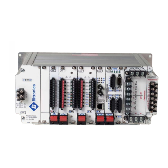
Novatech Bitronics M87X Series Manuals
Manuals and User Guides for Novatech Bitronics M87X Series. We have
1
Novatech Bitronics M87X Series manual available for free PDF download: Manual
Novatech Bitronics M87X Series Manual (184 pages)
Brand:
Novatech
| Category:
Measuring Instruments
| Size: 9 MB
Table of Contents
Table of Contents
3
Firmware Version
8
M87X MANUAL SET
10
Installation and Maintenance
11
Warranty and Assistance
11
Authorized Representative in the European Union
12
Copyright Notice
12
Trademarks
12
Safety Section
14
Description
17
Introduction
17
Features
17
Specifications
17
Standards and Certifications
26
Revenue Accuracy
26
Environment
26
Housing and Backplane
31
Installation
34
Initial Inspection
34
Protective Ground/Earth Connections
34
Instrument Mounting
34
Surge Protection
34
Cleaning
34
Removal and Installation of Modules
35
Host / Analog-Digital Signal Processor Module H11/H12 and A10
36
Host Board
36
Serial Port/Front Panel Board
36
Service Port (P1)
36
Standard Serial Ports (P2, P3, P4)
37
Diagnostic Status Led's (S1, S2, S3, S4)
38
RS485 Connections
38
Self-Test Modes
47
System Clock
48
A10 Analog-Digital Signal Processor Board
48
Calibration
48
Instantaneous Measurement Principles
48
Sampling Rate and System Frequency
48
Measurements
49
Current (1/4-Cycle Update)
49
Neutral and Residual Current (1/4-Cycle Update)
49
Voltage Channels (1/4-Cycle Update)
49
Power Factor (1-Cycle Update)
50
Watts / Volt-Amperes (Vas) / Vars (1-Cycle Update)
50
Geometric VA Calculations
51
Arithmetic VA Calculations
51
Equivalent VA Calculations
52
Energy (1-Cycle Update)
52
Frequency (1-Cycle Update)
53
Demand Measurements (1-Second Update)
53
Ampere and Fundamental Ampere Demand
54
Volt Demand
54
Power Demands (Total Watts, Vars, and Vas)
55
Voltage THD Demand
55
Current TDD Demand
55
Demand Resets
55
Demand Interval
55
Harmonic Measurements (1-Cycle Update)
56
Voltage Distortion (THD) (1-Cycle Update)
56
Current Distortion (THD and TDD) (1-Cycle Update)
56
Fundamental Current (1-Cycle Update)
57
Fundamental Neutral Current (M871 Only) (1-Cycle Update)
57
Fundamental Voltage (1-Cycle Update)
57
Fundamental Watts / Volt-Amperes (Vas) / Vars (1-Cycle Update)
58
K-Factor (1-Cycle Update)
58
Displacement Power Factor (1-Cycle Update)
58
Phase Angle (1-Cycle Update)
58
Resistance, Reactance, Impedance (1-Cycle Update)
59
Slip Frequency (1-Cycle Update)
59
Individual Phase Harmonic Magnitudes and Phase Angles (1-Cycle Update)
59
Temperature (1-Second Update)
59
Symmetrical Components (1-Cycle Update)
59
Supply Voltage and Current Unbalance (1-Cycle Update)
59
Flicker
60
Fault Analysis
60
Line Parameters
60
Peak Current
60
Status Indication and Reset
60
SOELOG Output
61
Protocol Output
61
List of Available Measurements
63
Functional Description
66
Passwords
66
Configuration
66
Triggering
68
Threshold Trigger
68
Trigger Hysteresis
68
Digital Input Trigger
70
Edge and Level Triggers
70
Manual Trigger
71
Logical Combinations of Triggers
71
Cross Triggering Multiple 70 Series Units (Inter-Triggering)
71
Fault Distance Triggers
71
Periodic Triggers
72
Recording
73
Waveform Recorder
73
Default Frequency Setting for Waveform Recorder
75
Indicating Waveform Records with Digital Outputs
75
Retrieving and Deleting Waveform Recorder Files
76
Disturbance Recorders
76
Indicating Disturbance Records with Digital Outputs
77
Retrieving and Deleting Disturbance Recorder Files
77
Trend Recorder
78
Retrieving Trend Records
78
Comtrade Format
78
Comtrade ZIP Files
79
IEEE Long File Naming Convention
79
Voltage Fluctuation Table (VFT) File
81
Sequence of Events (SOE) File
83
Sequence of Events Recorder (SER) File
83
M87X File System
84
FTP Server
84
Introduction to FTP
85
M87X FTP Implementation
85
Zmodem, TELNET, and Command Line Interface
86
Assigning Pulse Outputs to Energy Values
87
Irig-B
87
Overview
87
Introduction to IRIG Standards
88
Time Code Format (Rate Generation)
88
Format Designation
88
Carrier/Resolution
89
Coded Expressions
89
M87X IRIG-B Implementation
89
M87X IRIG-B Receiver
89
M87X IRIG-B Decoder
89
M87X IRIG-B Time Qualifier
90
Determining the Correct Year
90
Methods of Automatic Clock Adjustments
91
Types of M87X Clock Synchronization
91
Frequency Adjustments and Free Wheeling
91
Permanent IRIG-B Source Connection
92
Stages of IRIG-B Synchronization and Accuracy
92
Power-Up Stage
92
Time Lock Stage
92
Frequency Lock Stage
93
Final Lock Stage
93
Notes on Operation
93
IRIG-B Electrical Specifications
93
IRIG-B Port Wiring Instructions
93
Demodulated)
93
Modulated IRIG-B
94
Setup Instructions for Use of the M87X Modulated IRIG-B Converter
94
Wave, Amplitude Modulated, IRIG-B Master)
94
Time Sync & Setting
95
Time Sync Status Registers
95
Manual Time Setting by Command-Line Instruction
95
Unsolicited DNP Time Set (DNP Master Sets the IED Clock)
95
IRIG-B Time Sync (Time-Synchronization Via Dedicated IED Port)
95
UCA) Network Time Synchronization - Time Synchronization over Ethernet
96
SNTP (Simple Network Time Protocol) - Time Synchronization over Ethernet
96
Using the M87X with a Bitronics Analog Output Converter
97
Automatic Event Notification
97
Email Notifications
97
Serial Notifications
97
Data Sent
97
Error Recovery
98
Example
98
Control Characters
98
Power Supply V10
99
Introduction
99
Features
99
Specifications
99
Environmental
100
Physical
100
Power Supply and Protective Ground (Earth) Connections
101
Overcurrent Protection
101
Supply/Mains Disconnect
101
Signal Input Module S10 - S12, S1C (M871), S13 - S17, S2C (M872)
102
Introduction
102
Features
102
Specifications
103
Current Input (CT) Connections
109
Voltage Input (VT) Connections
110
Overcurrent Protection for Voltage Input (VT) Connections
110
Current Measurements
111
Neutral Current (Residual Current) for WYE Connections
111
Voltage Measurements
111
Changing Transformer Ratios
111
User (External Transformer) Gain and Phase Correction
111
Calibration
112
Installation and Calibration for the S1C Option
112
Ethernet Module P10, P11, P12 or E1, E3 Option with H12 Host
124
Introduction
124
Features
125
Specifications (for P1X Modules Unless Otherwise Noted)
125
Environmental
126
Physical
126
Hot Swap (HS) Compatibility (P1X Modules)
126
Hardware Configuration
126
Cabling
127
Connections
127
Troubleshooting the Connection
127
Indicators
127
Software Configuration
128
Technical Details
128
Jumper Settings (P1X)
130
Troubleshooting
131
PHYSTS Register Contents (P1X)
132
Statistics Gathered by Ethernet Driver
133
Digital Input / Output Module P30A, P31, P33
134
Introduction
134
Features
134
Specifications
135
Environmental
136
Physical
136
Hot Swap (HS) Compatibility
136
Description
136
P30A
136
P31
137
P33
137
System Design Considerations
137
Input / Output Impedance
137
Input Assignments
137
Debounce Time Setting
138
Setting Digital I/O Module Jumpers
141
Disassembly of the P30A Module
141
Disassembly of the P31 Module
141
Compactpci TM Interface Board (692) Jumper Settings
142
I/O Board (693) Jumper Settings
143
Health Status Digital Output Setting (Optional Assignment of Digital Output 1 of Module 0)
145
Disassembly of the P33 Module
145
Digital Output Board (803) Jumper Settings
145
Transducer Input Module P40
147
Introduction
147
Features
148
Specifications
149
Environmental
149
Physical
150
Hot Swap (HS) Compatibility
150
Description
150
System Design Considerations
150
Input Type Jumper Settings
150
Transducer Input Scaling Configuration
152
Setting the Data Update Rate (Poll Rate) for P40 Transducer Inputs
152
Appendix A - Cross Triggering
154
Appendix B - Firmware Version History
170
Advertisement
Advertisement
Related Products
Novatech Bitronics M65 Series
Novatech Bitronics M650
Novatech Bitronics 50 Series
Novatech Bitronics M660
Novatech Bitronics M663
Novatech Bitronics M661
Novatech MC9200 Series
Novatech SCILogex MX-T6-Pro
Novatech SCILogex MX-T6-S
Novatech 1635
Novatech Categories
Measuring Instruments
Transmitter
Controller
Synthesizer
Transducer
More Novatech Manuals
Login
Sign In
OR
Sign in with Facebook
Sign in with Google
Upload manual
Upload from disk
Upload from URL