
Related Manuals for H3C SR6602-X1 AC


Summary of Contents for H3C SR6602-X1 AC
- Page 1 H3C SR6602-X Routers Installation Guide New H3C Technologies Co., Ltd. http://www.h3c.com.hk Document version: 6PW105-20170323...
- Page 2 , H3CS, H3CIE, H3CNE, Aolynk, Care, , IRF, NetPilot, Netflow, SecEngine, SecPath, SecCenter, SecBlade, Comware, ITCMM and HUASAN are trademarks of New H3C Technologies Co., Ltd. All other trademarks that may be mentioned in this manual are the property of their respective owners Notice The information in this document is subject to change without notice.
- Page 3 Preface The H3C SR6602-X Routers Installation Guide includes eight chapters, which describe the hardware features of the H3C SR6602-X Routers and provide examples to help you install the router. This preface includes the following topics about the documentation: • Audience.
- Page 4 Convention Description Multi-level menus are separated by angle brackets. For example, File > Create > > Folder. Symbols Convention Description An alert that calls attention to important information that if not understood or followed WARNING! can result in personal injury. An alert that calls attention to important information that if not understood or followed CAUTION: can result in data loss, data corruption, or damage to hardware or software.
- Page 5 Obtaining documentation To access the most up-to-date H3C product documentation, go to the H3C website at http://www.h3c.com.hk To obtain information about installation, configuration, and maintenance, click http://www.h3c.com.hk/Technical_Documents...
-
Page 6: Table Of Contents
Contents Preparing for installation ···································································· 1 Safety recommendations ············································································································· 1 Safety symbols ··················································································································· 1 General safety recommendations ··························································································· 1 Electricity ··························································································································· 1 Laser safety ······················································································································· 1 Router moving ···················································································································· 2 Examining the installation site ······································································································· 2 ... - Page 7 Connecting a serial port cable ······························································································ 30 Logging in to the router and configuring basic settings ··························· 31 Login methods ························································································································ 31 Logging in through the console port ····························································································· 31 Preparation ······················································································································ 31 Setting up a configuration environment ·················································································· 31 ...
- Page 8 Power module failures ··············································································································· 59 Fan failures ···························································································································· 60 Fan tray is absent ·············································································································· 60 ALM LED is red ················································································································· 60 HIM/MIM failures······················································································································ 61 Configuration system problems ··································································································· 61 No terminal display ············································································································ 61 ...
- Page 9 Numbering interfaces ················································································································ 90 Example ································································································································ 91 Index ··························································································· 92 ...
-
Page 10: Preparing For Installation
Always verify that the power has been disconnected. Laser safety The H3C SR6602-X routers are Class 1 laser devices. WARNING! • Do not stare into any fiber port when the router has power. The laser light emitted from the optical fiber may hurt your eyes. -
Page 11: Router Moving
Router moving When you move an SR6602-X router, follow these guidelines: • Move and unpack the router carefully to avoid router damage. • Use a safety hand truck when you move a heavy device or multiple devices. • Before you move the router, remove all the cables, USB devices, mounting brackets, and cable management brackets. -
Page 12: Altitude
Altitude Table 3 Altitude requirements Item Altitude Operating altitude –60 m (–196.85 ft) to 4 km (2.49 miles) Storage altitude –60 m (–196.85 ft) to 4.5 km(2.8 miles) Cleanliness Dust buildup on the chassis might result in electrostatic adsorption, which causes poor contact of metal components and contact points, especially when indoor relative humidity is low. -
Page 13: Esd Prevention
Figure 1 Airflow (SR6602-X1) • Make sure there is enough space (greater than 10 cm (3.94 in)) around the air intake and outlet vents on the router for good ventilation. • Make sure the installation site has a good cooling system. ESD prevention CAUTION: •... -
Page 14: Emi
Figure 2 Attaching an ESD wrist strap (1) ESD wrist strap (2) Lock (3) Alligator clip All electromagnetic interference (EMI) sources, from outside or inside of the switch and application system, adversely affect the switch in the following ways: • A conduction pattern of capacitance coupling. -
Page 15: Power Supply
A minimum of 65 mm (2.56 in) Width—440 mm (17.32 in) between the front rack posts and the • Depth—566 mm (22.28 in) • SR6602-X1 AC front door. 480 mm (18.90 in) for the • • SR6602-X2 AC A minimum of 533 mm (20.98 in) -
Page 16: Accessories
Accessories Front mounting 3 m (9.84 ft) Console cable Rear mounting bracket and cable Load-bearing grounding cable (supplied with bracket (supplied management screw (supplied (supplied with router) with router) bracket (supplied with router) router) with router) Rubber feet M6 screw Cage nuts ESD wrist strap Cable tie... -
Page 17: Installing The Router
Installing the router NOTE: The fan tray, power modules, FIPs, and interface modules are hot swappable. Installation flow Figure 3 SR6602-X installation flow Check before installation Follow these guidelines to prepare for installing an SR6602-X router: • Make sure you have read “Preparing for installation”... -
Page 18: Unpacking The Router
Unpacking the router Unpack the router as shown in Figure Figure 4 Unpacking the router Installing the router in a 19-inch rack Before you install the router to a rack, wear an ESD wrist strap. For how to wear an ESD wrist strap, “ESD prevention.”... -
Page 19: Grounding The Router
Figure 7 Installing the front mounting brackets and load-bearing screws Install the router to the rack. CAUTION: This task requires at least two people. Figure 8 Installing the router to the rack Move the router to an appropriate location in Attach the front mounting brackets to the the rack front rack posts... -
Page 20: Connecting The Grounding Cable
To install the ring terminal: Cut the grounding cable as appropriate for connecting to the grounding strip, and strip 5 mm (0.20 in) of insulation sheath by using a wire stripper. Insert the bare metal part through the black insulation covering into the end of the ring terminal. Crimp the metal part of the cable to the ring terminal with a crimper. -
Page 21: Installing A Power Module
Table 7 Connecting the grounding cable Installing a power module Before you install a power module, make sure the power switch is off and the router is well grounded. The procedures for installing an AC power module and a DC power module are the same. The following uses an AC power module as an example. -
Page 22: Installing A Fip Module
NOTE: • For the power module LED description, see “Appendix B LEDs.” • An AC power module and a DC power module cannot be installed on the same router. Installing a FIP module NOTE: Before you install a FIP module, make sure the ejector levers are in the open position away from the FIP module panel. -
Page 23: Installing A Mim
To install a HIM: Locate the slot to install the HIM on the FIP module. A HIM occupies two slots of the FIP module. Loosen the captive screws on a filler panel with a Phillips screwdriver, and then use a flat-blade screwdriver to prize the filler panel to remove it from the router. -
Page 24: Installing A Cf Card
Installing a CF card Press the spring clip at the right of the CF card cover to open it. Figure 14 Open the CF card cover Press the ejector button next to the CF card slot. Insert the CF card into the slot and make sure it does not project from the slot. -
Page 25: Connecting The Power Cord
Connecting the power cord Connecting an AC power cord Make sure the router is well grounded, and the power switch on the router is in the OFF position. Pull the bail latch upwards. Connect one end of the AC power cord to the AC-input power receptacle on the router. Pull the bail latch down to secure the plug to the power receptacle. - Page 26 Figure 19 Tighten the screws Connect the two wires at the other end of the power cord to a DC power source.
-
Page 27: Connecting The Router To The Network
Connecting the router to the network Connecting the AUX cable Overview An AUX console cable is an 8-core shielded cable, with a crimped RJ-45 connector at one end for connecting to the AUX port of the router, and DB-25 and DB-9 male connectors at the other end for connecting to the serial port of the modem. -
Page 28: Connecting An Ethernet Cable
Connecting an Ethernet cable Overview 10/100 Mbps Ethernet uses category-5 twisted pair cables, while 1000 Mbps Ethernet uses category-5 enhanced or category-6 twisted pair cables. Twisted pair cables include straight-through cables and crossover cables. Category-5 cables provide a transmission frequency of 100 MHz for voice and data transmission; they are mainly used in 100Base-T and 10Base-T networks. -
Page 29: Making An Ethernet Cable
Table 8 Straight-through cable pinouts Pinout No. Orange/white Orange/white Orange Orange Green/white Green/white Blue Blue Blue/white Blue/white Green Green Brown/white Brown/white Brown Brown Table 9 Crossover cable pinouts Pinout No. Orange/white Green/white Orange Green Green/white Orange/white Blue Blue Blue/white Blue/white Green Orange Brown/white... -
Page 30: Connecting An Ethernet Cable
Connecting an Ethernet cable Plug one end of an Ethernet twisted pair cable into the copper Ethernet port (RJ-45 port) to be connected on the router and the other end of the cable into the Ethernet port of the peer device. The 10/100/1000Base-T copper ports of the router support MDI/MDI-X auto-sensing. -
Page 31: Fiber Cable Overview
Figure 25 SFP+ transceiver module Fiber cable overview You can use an optical fiber to connect a fiber Ethernet port or 10 Gbps Ethernet port. In addition, an optical fiber can connect fiber ports on interface modules. Optical fibers feature low loss and long transmission distance. Optical fibers can be classified into single mode fibers and multi-mode fibers. -
Page 32: Connecting A Fiber Cable
• The SR6602-X supports LC fiber cables only. • Some cards of the H3C SR6602-X router provide shielded covers for the fiber ports (such as SFP ports). Before using such fiber ports, remove the shielded covers. Keep the shielded covers properly. -
Page 33: Connecting An E1/T1 Cable
Figure 27 Connecting a fiber cable Connecting an E1/T1 cable E1/T1 cable overview E1 cable You can use an 8E1 interface cable to connect to MIM-8E1(75)/MIM-8E1(75)-F modules. Figure 28 8E1 splitter cable NOTE: The coaxial connector and 75-ohm E1 adapter cable are optional accessories, and must be purchased separately if needed. -
Page 34: Connecting An E1/T1 Cable
T1 cable You can use an 8T1 interface cable to connect to MIM-8T1/MIM-8T1-F modules. Figure 29 8T1 splitter cable CAUTION: • When connecting the interface cable, pay attention to the mark on the interface to avoid wrong insertion, which may damage the interface module or even the router. •... - Page 35 Figure 30 Connect an E1 75-ohm cable • If you want to extend the cable, connect each BNC connector of the E1 75-ohm cable to one end of a coaxial connector, and connect the remote device to the other end of the coaxial connector through an E1 75-ohm adapter cable.
-
Page 36: Connecting A Ce3/Ct3 Cable
Figure 33 Connecting an 8T1 cable Connecting a CE3/CT3 cable CE3/CT3 cable overview You can use a CE3/CT3 interface cable to connect the MIM-1CE3 and MIM-1CT3 modules. Figure 34 E3/T3 cable CAUTION: As a best practice, install a special lightning protector at the input end of the E3/T3 cables to protect them against lightning strikes more efficiently when they are routed outdoors. -
Page 37: Connecting A Serial Port Cable
Figure 35 Connecting a CE3/CT3 cable Connecting a serial port cable Overview You can use a serial port cable to connect to the MIM-2SAE/MIM-4SAE/MIM-8SAE module. Select a serial port cable according to the link type. Figure 36 V.24 DTE cable Figure 37 V.24 DCE cable... - Page 38 Figure 38 V.35 DTE cable Figure 39 V.35 DCE cable Pos.28 Pos.1 Figure 40 X.21 DTE cable Pos.1 Pos.1 Pos.15 Pos.28 Figure 41 X.21 DCE cable Figure 42 RS449 DTE cable...
-
Page 39: Connecting A Serial Port Cable
Figure 43 RS449 DCE cable Figure 44 RS530 DTE cable Figure 45 RS530 DCE cable Connecting a serial port cable Check port type of the peer device and choose the synchronous serial interface cable of correct type. Plug the D28 end of the synchronous serial interface cable into the D28 interface of the SAE interface module. -
Page 40: Logging In To The Router And Configuring Basic Settings
Logging in to the router and configuring basic settings Login methods The following login methods are available for you to log in to the router: • Logging in through the console port, which is the most common way to log in to a router and also the prerequisite for configuring other login methods. -
Page 41: Setting Terminal Parameters
Figure 46 Connecting the console cable Setting terminal parameters To set terminal parameters, for example, on a Windows XP HyperTerminal: Select Start > All Programs > Accessories > Communications > HyperTerminal. The Connection Description dialog box appears. Enter the name of the new connection in the Name field and click OK. Figure 47 Connection description for the HyperTerminal Select the serial port to be used from the Connect using list, and click OK. - Page 42 Figure 48 Setting the serial port used by the HyperTerminal connection Set Bits per second to 9600, Data bits to 8, Parity to None, Stop bits to 1, and Flow control to None, and click OK. Figure 49 Setting the serial port parameters Select File >...
- Page 43 Figure 50 HyperTerminal window On the Settings tab, set the emulation to VT100 and click OK. Figure 51 Setting terminal emulation in aaa Properties dialog box...
-
Page 44: Verification Before Power-On
Press Ctrl+D to access BASIC-BOOTWARE MENU Press Ctrl+T to start memory test Booting Normal Extend BootWare..**************************************************************************** H3C SR66 Routers BootWare, Version 1.12 **************************************************************************** Copyright (c) 2004-2012 Hangzhou H3C Technologies Co., Ltd. Compiled Date : Nov 14 2012 CPU Type : P4080 CPU L1 Cache... -
Page 45: Logging In To The Router Through Telnet/Ssh
Connect the AUX port to the configuration terminal by using the console cable. Then you can log in to the router through the AUX port. NOTE: For more information about how to log in to the router through the AUX port, see H3C SR6600 Router Series Fundamentals Configuration Guide. Displaying the initial configuration After you log in to the router for the first time, use the display current-configuration command to display the initial configuration of the router. -
Page 46: Configuring Basic Settings
H3C domain default enable system domain system access-limit disable state active idle-cut disable self-service-url disable user-group system group-attribute allow-guest interface NULL0 interface GigabitEthernet0/0/0 interface GigabitEthernet0/0/1 interface GigabitEthernet0/0/2 interface GigabitEthernet0/0/3 interface M-GigabitEthernet0/0/0 load xml-configuration user-interface con 0 user-interface aux 0... - Page 47 Step Command Remarks ip route-static dest-address { mask | mask-length } { next-hop-address | interface-type By default, the preference of a interface-number static route is 60, tag is 0, and no [ next-hop-address ] | description is configured. Specify a static route vpn-instance Do not specify the permanent d-vpn-instance-name...
-
Page 48: Replacement Procedures
Replacement procedures Safety recommendations Always wear an ESD wrist strap or ESD gloves when replacing the modules. When operating a pluggable module, such as a FIP module, memory module, CF card, or HIM/MIM, follow these guidelines: Ensure good alignment with the slot to avoid damage to the module during installation or removal. -
Page 49: Replacing A Him
To replace a FIP module, for example, FIP-20: Determine the FIP module to be removed. This section takes the FIP module in slot 3 as an example. Use a Philips screwdriver to loosen the captive screws of the FIP module to be removed until all spring pressure is released. -
Page 50: Replacing A Mim
Figure 54 Pulling the HIM out of the slot If you do not install a new HIM in the slot, install a blank panel. To install a new HIM, see “Installing a HIM.” Replacing a MIM NOTE: To replace a MIM module when the router is running, perform the remove slot slot-number command and then unplug the module. -
Page 51: Replacing A Transceiver Module
Press the ejector button next to the CF card. The ejector button moves outward so that it projects from the panel. Figure 56 Press the ejector button Press the ejector button again. This ejects the CF card partially out of its slot. Pull the CF card out of its slot. -
Page 52: Replacing A Fan Tray
Remove the optical fibers from the transceiver module. Pivot the clasp down to the horizontal position. Holding the handle of the transceiver module, gently pull the transceiver module out. Figure Insert the plastic plug to the removed transceiver module, and put the transceiver module into its original shipping materials. -
Page 53: Replacing A Memory Module
H3C for permission. Otherwise, H3C shall not be liable for any consequence caused thereby. • Use the memory modules provided by H3C only. Otherwise, the router may be unable to operate properly. -
Page 54: When To Replace A Memory Module
Figure 62 Memory module slot (1) Release latch (2) Memory module slot When to replace a memory module Memory modules are removable components of the router. You need to replace a memory module in the following situations: • More memory is needed to upgrade the application program. •... - Page 55 Figure 63 Opening the chassis cover Replacing a memory module CAUTION: Align the polarization notch of the memory module with the key in the connector when you insert a memory module. Figure 64 Replacing a memory module...
-
Page 56: Hardware Management And Maintenance
Comware Software, Version 5.20, A2605 Copyright (c) 2004-2011 Hangzhou H3C Tech. Co., Ltd. All rights reserved. H3C SR6602-X uptime is 0 week, 0 day, 0 hour, 1 minute Slot 0: SR6602-X2 uptime is 0 week, 0 day, 0 hour, 1 minute... -
Page 57: Displaying The Detailed Information About A Module
multiple functional modules of the router. This command displays the output of the display clock, display version, display device, and display current-configuration commands. • To save the operational statistics of each functional module of the router, type y when the system prompts you to save or display the diagnostic information. -
Page 58: Displaying The Electrical Label Information Of A Module
MAC address, and vendor name. <Sysname> display device manuinfo Slot 0: DEVICE_NAME:SR6602-X2 DEVICE_SERIAL_NUMBER:NONE MAC_ADDRESS:NONE MANUFACTURING_DATE:2011-12-12 VENDOR_NAME:H3C Slot 1: DEVICE_NAME:RT-FIP-20 DEVICE_SERIAL_NUMBER:NONE MAC_ADDRESS:NONE MANUFACTURING_DATE:2011-12-12 VENDOR_NAME:H3C Use the display device manuinfo slot slot-number command to display the electrical label information of the module in the specified slot. -
Page 59: Displaying The Cpu Usage Of A Module
Field Description MAC address of the router or interface module: • An MPU has a MAC address. MAC_ADDRESS • A service module does not have a MAC address, and the field is displayed as NONE. MANUFACTURING_DATE Manufacturing data of the router or interface module VENDOR_NAME Vendor name The operation is not supported... -
Page 60: Displaying The Cf Card Information
Displaying the CF card information Use the display device cf-card command to display the CF card information. <Sysname> display device cf-card Slot No. Dev No. Status Size(M) ----------------------------------------------- Normal Absent Table 16 Output description Field Description Slot No Slot number of the CF card Device number of the CF card: •... -
Page 61: Displaying The Alarming Thresholds Of A Module
Field Description The power supply state: • Normal—The power supply is operating properly. State • Absent—The power supply is not in position. • Fault—The power supply fails. Displaying the alarming thresholds of a module When the router is operating, too high a temperature and too low a temperature of a module affect the normal operation of the router. -
Page 62: Configuring A Combo Interface
Output queue : (FIFO queuing : Size/Length/Discards) 0/1024/0 Last clearing of counters: Never Last 5 seconds input rate 0.00 bytes/sec, 0 bits/sec, 0.00 packets/sec Last 5 seconds output rate 0.00 bytes/sec, 0 bits/sec, 0.00 packets/sec Input: 0 packets, 0 bytes, 0 no buffers 0 broadcasts, 0 multicasts, 0 pauses 0 errors, 0 runts, 0 giants 0 crc, 0 align errors, 0 overruns... -
Page 63: Displaying Transceiver Module Information And Alarming Information
The system outputs alarm information for you to locate and troubleshoot faults of transceiver modules. For the H3C-customized transceiver modules, the system can also monitor the key parameters, such as temperature, voltage, laser bias current, TX power, and RX power. When these parameters are abnormal, you can take corresponding measures to prevent transceiver module faults. -
Page 64: Solving System Faults
] NOTE: For more information about the transceiver module displaying commands, see H3C SR6600 Router Series Command References. Solving system faults Solving system faults When the system detects faults (such as system instruction faults, invalid addresses, data overflow,... -
Page 65: Rebooting The Router
Table 20 To save the current configuration of the router: Purpose Command Remarks Save the current configuration to the specified file, but the save file-url Use either configuration file will not be set as the file for the next startup command Save the current configuration to the root directory of the storage Available in any... - Page 66 CAUTION: • If the main system software image file does not exist, do not use the reboot command to reboot the router. Specify the main system software image file first, and then reboot the router. • The precision of the rebooting timer is 1 minute. One minute before the rebooting time, the router prompts “REBOOT IN ONE MINUTE”...
-
Page 67: Troubleshooting
When the system is over-temperature. In this case, the system displays the following output: %Dec 7 11:17:01:436 2011 H3C DRVMSG/3/TEMP_ALARM: CPU temperature is greater than alarm upper limit in slot 0, index is 0. To solve the problem, check the output (such as the system temperature, insufficient available power,... -
Page 68: Fip Module Failure
If the cause cannot be located in the steps above and the problem persists, record the above information, and contact your local sales agent. Table 21 Router status LED description Status Remarks The power module is not in position. Steady green The power module is supplying power properly. -
Page 69: Fan Failures
Fan tray is absent After the router is booted, the following information may appear on the configuration terminal: #Dec 9 09:57:12:560 2011 H3C DEVM/1/FAN STATE CHANGES TO FAILURE: Trap 1.3.6.1.4.1.25506.8.35.12.1.6<hh3cfanfailure>: fan ID is 1 %Dec 9 09:57:12:560 2011 H3C DEVM/3/FAN_ABSENT: Fan 1 is absent. -
Page 70: Him/Mim Failures
To solve the problem, check whether any foreign object has entered the fan tray. If the cause cannot be located in the steps above and the problem persists, contact your local sales agent. HIM/MIM failures When a HIM/MIM is plugged while the router is running, the following information may appear on the configuration terminal: %Dec 30 09:54:10:264 2011 66mcp DRVICOUT/1/DrvIcOutStr: Card in Slot 4 Sublot 2 can not be recognized ! -
Page 71: No Response From The Serial Port
Make sure the Bits per second field is set to 9600 kbps. An incorrect bits per second may also cause the configuration terminal to display garbled characters. No response from the serial port If the serial port gives no response, verify that the serial port settings are correct. NOTE: For more information about the serial port settings, see “Setting terminal... - Page 72 Press Ctrl+D to access BASIC-BOOTWARE MENU Press Ctrl+T to start memory test Booting Normal Extend BootWare..**************************************************************************** H3C SR66 Routers BootWare, Version 1.12 **************************************************************************** Copyright (c) 2004-2012 Hangzhou H3C Technologies Co., Ltd. Compiled Date : Dec 26 2012 CPU Type : P4080 CPU L1 Cache...
-
Page 73: Dealing With Console Login Password Loss When Password Recovery Capability Is Enabled
The router starts up with empty configuration. To use the configuration in the next-startup configuration file, load the file in system view. <H3C> system-view [H3C] configuration replace file startup.cfg Current configuration will be lost, save current configuration? [Y/N]:n Info: Now replacing the current configuration. Please wait... -
Page 74: Dealing With User Privilege Level Password Loss When Password Recovery Capability Is Enabled
[H3C-ui-console0] authentication-mode password [H3C-ui-console0] set authentication password cipher 123456 To make the settings take effect after a reboot, save the running configuration to the next-startup configuration file. [H3C] save Dealing with user privilege level password loss when password recovery capability is enabled Reboot the router to access the EXTEND-BOOTWARE menu, and then enter 8. -
Page 75: Dealing With Password Loss When Password Recovery Capability Is Disabled
%Dec 7 11:49:16:436 2011 H3C DRVMSG/3/TEMP_WARNING: Environment temperature is greater than warning upper limit in slot 0, index is 1. #Dec 7 11:49:20:444 2011 H3C DEVM/1/BOARD TEMPERATURE UPPER:... -
Page 76: Interface Module, Cable, And Connection Failure
If the temperature inside the module still reaches the critical temperature threshold, power off the router immediately and contact your local sales agent. NOTE: For more information about the display environment command, see H3C SR6600 Router Series Fundamentals Command Reference. Interface module, cable, and connection failure After an HIM/MIM is installed and the router is powered on, the LEDs on the HIM/MIM panel may indicate abnormal operation. -
Page 77: Software Upgrade Failures
Software upgrade failures No response from the serial port The serial port gives no response. To solve the problem, check whether the serial port settings are correct (whether the Bits per second field is set to 9600 kbps). NOTE: For more information about the serial port settings, see “Setting terminal parameters.”... -
Page 78: Application File Missing Errors
550 Error: File xxx does not exist FTP: Error Writing Local File(Screen). To solve this problem, type the correct file name. The configuration of the network port is incorrect. FTP: Unrecognized host or wrong IP address! To solve this problem, configure the network port correctly, and make sure the network port is up and you can successfully ping the FTP server from the network port. -
Page 79: Appendix A Chassis Views And Technical Specifications
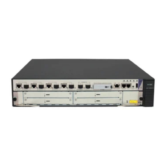
Appendix A Chassis views and technical specifications The H3C SR6602-X Router Series is a line of high-performance centralized product, which includes the SR6602-X1 and SR6602-X2. Chassis views Figure 66 SR6602-X1 front view (1) 1000 Mbps Ethernet port (2) CF card slot (CF CARD) -
Page 80: Dimensions And Weights
Figure 67 SR6602-X2 front view (1) 1000 Mbps Ethernet port (2) 10 Gbps Ethernet port (3) CF card slot (CF CARD) (4) CF card LED (5) Status LED (6) USB port (7) Reset button (RESET) (8) Auxiliary port (AUX) (9) Console port (CONSOLE) (10) Management Ethernet port (MANAGEMENT) (11) FIP slot (slot 1) Figure 68 SR6602-X1/X2 rear view... -
Page 81: Storage Media
Power modules specifications Each H3C SR6602-X router provides two power module slots, PWR1 and PWR2 on its rear panel, and is shipped with a filler panel on PWR2. You can install one or two power modules for the router as needed. -
Page 82: Ac Power Module
AC power module Figure 69 AC power module appearance (1) AC-input power receptacle (2) Power input status LED (3) Power output status LED (4) Handle (5) Power switch Table 27 AC power module specifications Item Specification Model PSR300-12A Rated voltage range 100 VAC to 240 VAC;... -
Page 83: Fan Tray Specifications
Table 28 DC power module specifications Item Specification Model PSR300-12D1 Rated voltage range –60 VDC to –48 VDC Maximum input current 10 A Maximum power 300 W Fan tray specifications Figure 71 Fan tray (1) Handle Table 29 Fan tray specifications Item Specification Model... -
Page 84: Console Port
Table 30 Port and slot specifications Item Description Console port AUX port USB port • SR6602-X1—Four GE combo interfaces Ethernet port • SR6602-X2—Four combo interfaces and two 10 GE ports CF card slot Interface module slot 1, supports FIP-10/20 Console port Table 31 Console port specifications Item Specification... -
Page 85: Combo Interface
Item Specification Interface type Automatic MDI/MDI-X Ethernet_II Frame format Ethernet_SNAP 10 Mbps, half/full-duplex Interface speed and duplex mode 100 Mbps, half/full-duplex 1000 Mbps, full-duplex Combo interface Copper Ethernet port Table 34 Copper Ethernet port specifications Item Specification Connector RJ-45 Interface type Automatic MDI/MDI-X Ethernet_II Frame format... - Page 86 Table 36 Transceiver modules for the SFP ports Max. Central Transmission Model Connector Optical fiber transmission wavelength rate distance 62.5/125 µm SFP-FE-SX- 2 km (1.24 1310 nm multi-mode 155 Mbps MM1310-A miles) optical fiber 9/125 µm 15 km SFP-FE-LX- 1310 nm single-mode 155 Mbps SM1310-A...
-
Page 87: 10 Gbps Ethernet Port
NOTE: • Use transceiver modules for the fiber ports provided by H3C only. The router might be incompatible with transceiver modules from other vendors. The system generates an alarm when a transceiver module from another vendor is installed. • The BIDI modules must be used in pairs. For example, if you install the SFP-GE-LX-SM1310-BIDI in the local port, you must install the SFP-GE-LX-SM1490-BIDI in the peer port. - Page 88 FIP-10 Front panel Figure 72 FIP-10 front panel (1) Slot 4 (2) Slot 3 (3) OPEN BOOK mark (4) Status LED (RUN) (5) Slot 1 (6) Slot 2 The OPEN BOOK mark indicates that the operator must read the following sections before working with the FIP: Table 39 References for FIP operations Operation...
-
Page 89: Interface Modules
Ethernet, POS, and E1. NOTE: • No interface modules are supplied with the router. Purchase them yourself. • An interface module must be installed on a FIP. • For information about interface module specifications, see H3C SR6600 Routers Interface Module Guide. -
Page 90: Appendix B Leds
The system is accessing the CF card. In this state, (yellow/green) Flashing green do not remove the CF card. Steady yellow It is a non H3C CF card. The power module is not in position. Steady green The power module is supplying power properly. PWR1... -
Page 91: Sr6602-X2 Panel Leds
Status Description The system is operating properly and there is no alarm. A fault has occurred. In this state, check the system Steady red log immediately. (red) The system is seriously faulty. An immediate action Flashing fast at 8 Hz is needed. - Page 92 The system is accessing the CF card. In this state, (yellow/green) Flashing green do not remove the CF card. Steady yellow It is a non H3C CF card. The power module is not in position. Steady green The power module is supplying power properly. PWR1...
-
Page 93: Fip Leds
Status Description No link is present. Steady green A 1000 Mbps link is present. Data is being received or transmitted at 1000 SFP0 through Flashing green Mbps. SFP3 (yellow/green) Steady yellow A 100 Mbps link is present. Flashing yellow Data is being received or transmitted at 100 Mbps. No link is present. -
Page 94: Him/Mim Leds
HIM/MIM LEDs For description of HIM/MIM LEDs, see H3C SR6600 Routers Interface Module Guide. Power module LEDs Figure 78 AC power module LED Table 44 AC power module LED description Status Description No power is input or the power module has an input problem. -
Page 95: Appendix C Cable Management
Appendix C Cable management When an SR6602-X router is mounted in a 19-inch standard rack, the interface cables are routed through the cable management brackets, bound at cabling racks on chassis sides, and then routed up or down, depending on the available equipment room condition. The power cables run along the two sides of the chassis and out of the chassis either from the chassis top or the raised floor depending on the equipment room conditions (power distribution cabinet, lightning protection box, and connector strip, etc.) of the exchange office. - Page 96 Figure 80 Correct and incorrect cable binding • The cable bend radius at connectors must be at least 5 times the cable diameter, and must be at least twice the cable diameter away from the connectors. • Route different types of cables (for example, power cables, and signal cables) separately. If they are close to one another, cross them over one another.
- Page 97 Figure 82 Binding the cables • Route, bind, and attach excess cables for easy, safe maintenance activities and proper operations. • Do not tie the power cables to the slide rails. • When you connect a cable to an articulated part, for example, when you connect a grounding cable to a cabinet door, leave enough slack in cables and make sure they are not stressed from any movement of the part.
-
Page 98: Cable Routing Example
Cable bundle diameter (mm) Space between bundles (mm) 200 to 300 • Do not tie cables or bundles in a knot. • The metal parts of the crimped cold-pressed terminal blocks (such as circuit breaker) cannot protrude beyond the blocks. Cable routing example Cables on an SR6602-X router can be routed as shown in Figure... -
Page 99: Appendix D Arranging Slots And Numbering Interfaces
Appendix D Arranging slots and numbering interfaces Slot arrangement The router provides many types of interfaces, such as console, AUX, GigabitEthernet, serial (synchronous), POS, and E1 ports. This chapter describes how these interfaces are numbered. Figure 85 Slot arrangement on the SR6602-X1 Figure 86 Slot arrangement on the SR6602-X2 NOTE: Figure 85... - Page 100 • X—Number of the slot where the FIP resides. Different HIMs/MIMs on the same FIP have the same slot number X. • Y—Sub-slot number, the number of the slot where the HIM/MIM resides on the FIP. Different interfaces on the same HIM/MIM have the same sub-slot number Y. •...
- Page 101 Index A C D E F G H I L N P R S U Accessories,7 HIM/MIM failures,61 Application file missing errors,69 HIM/MIM LEDs,85 Available slots for FIP-10/FIP-20,90 Installation flow,8 Cable management guidelines,86 Installing a CF card,15 Cable routing example,89 Installing a FIP module,13 Chassis...
- Page 102 Safety recommendations,1 Storage media,72 Safety recommendations,39 Saving the current configuration of the router,55 Unpacking the router,9 Slot arrangement,90 Software upgrade failures,68 Solving system faults,55...
Need help?
Do you have a question about the SR6602-X1 AC and is the answer not in the manual?
Questions and answers