Table of Contents
Advertisement
Advertisement
Table of Contents

Related Manuals for 2N IP Force


Summary of Contents for 2N IP Force
- Page 1 ® 2N IP Force Security IP Intercom Installation Manual Version: 2.13 www.2n.cz...
- Page 2 2N TELEKOMUNIKACE a.s. administers the FAQ database to help you quickly find information and to answer your questions about 2N products and services. On www. faq.2n.cz you can find information regarding products adjustment and instructions for optimum use and procedures „What to do if...".
- Page 3 The 2N TELEKOMUNIKACE a.s. is the holder of the ISO 9001:2009 certificate. All development, production and distribution processes of the company are managed by this standard and guarantee a high quality, technical level and professional aspect of all our products.
-
Page 4: Table Of Contents
2.4 Extending Module Connection 2.5 Button Tags 3. Function and Use 3.1 Configuration 3.2 Control 3.3 Maintenance 3.4 Downloads 4. Technical Parameters 5. Supplementary Information 5.1 Troubleshooting 5.2 Directives, Laws and Regulations 5.3 General Instructions and Cautions 2N TELEKOMUNIKACE a.s., www.2n.cz 4/117... -
Page 5: Product Overview
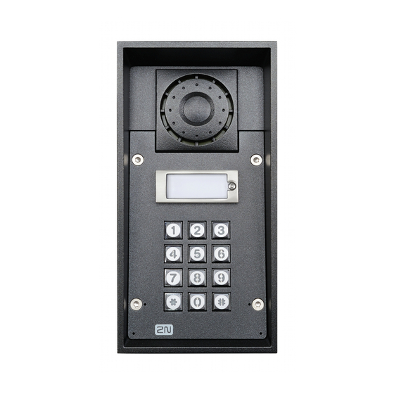
® IP Force can be equipped with a numerical keypad to be used as a code lock for lock switch activating or telephone/subscriber number dialling. 2N TELEKOMUNIKACE a.s., www.2n.cz 5/117... - Page 6 Audio codecs (G.711, G.729, G.722, L16/16kHz) HTTP server for configuration SNTP client for time synchronisation with server RTSP server for video streaming SMTP client for e-mail sending TFTP client for automatic configuration and firmware update 2N TELEKOMUNIKACE a.s., www.2n.cz 6/117...
- Page 7 TFTP client for automatic configuration and firmware update 2N TELEKOMUNIKACE a.s., www.2n.cz 7/117...
-
Page 8: Components And Associated Products
1.1 Components and Associated Products ® IP Force Components and Associated Products: 2N TELEKOMUNIKACE a.s., www.2n.cz 8/117... - Page 9 Basic Units One-Button 2N Part No. 9151101W 1 button Axis Part No. 01336-001 control of two electric locks possibility of connecting additional switch 10 W loudspeaker, IP69K Part No. 9151101CW IP69K 1 button camera 10 W loudspeaker, IP69K extra robust version...
- Page 10 One-Button 2N Part No. 9151101CHW IP69K Axis Part No. 01337-001 1 button HD camera 10 W loudspeaker, IP69K extra robust version control of two electric locks possibility of connecting additional switch 2N Part No. 9151101RPW 1 button, pictograms, Axis Part No. 01335-001...
- Page 11 10 W loudspeaker, IP69K 2N Part No. 1 button, pictograms, 9151101CHRPW with HD camera, Axis Part No. 01334-001 possibility of connecting card reader control of two electric locks possibility of connecting additional switch 10 W loudspeaker, IP69K 2N TELEKOMUNIKACE a.s., www.2n.cz 11/117...
- Page 12 One-Button 2N Part No. 9151101KW 10 W loudspeaker, IP69K Axis Part No. 01338-001 1 button keypad control of two electric locks possibility of connecting additional switch Part No. 9151101CKW 10 W loudspeaker, IP69K 1 button keypad camera control of two electric locks possibility of connecting additional switch 2N TELEKOMUNIKACE a.s., www.2n.cz...
- Page 13 Two-Button 2N Part No. 2 buttons 9151102CHRW HD camera Axis Part No. 01340-001 possibility of connecting card reader control of two electric locks possibility of connecting additional switch 10 W loudspeaker, IP69K 2N TELEKOMUNIKACE a.s., www.2n.cz 13/117...
- Page 14 10 W loudspeaker, IP69K 2N Part No. 9151102RW 2 buttons Axis Part No. 01341-001 possibility of connecting card reader control of two electric locks...
- Page 15 Two-Button Part No. 9151102-X1 2 buttons 10W loudspeaker, IP69K 2 buttons with „INFO“ and „SOS“ labels anti-vandal buttons made of stainless steel note: Customization available per request 2N TELEKOMUNIKACE a.s., www.2n.cz 15/117...
- Page 16 Four-Button 2N Part No. 9151104W 10 W loudspeaker, IP69K Axis Part No. 01342-001 4 buttons control of two electric locks possibility of connecting additional switch Part No. 9151104CW 10 W loudspeaker, IP69K 4 buttons camera control of two electric locks possibility of connecting additional switch 2N TELEKOMUNIKACE a.s., www.2n.cz...
- Page 17 Four-Button 2N Part No. 9151104CHW 10 W loudspeaker, IP69K Axis Part No. 01343-001 4 buttons HD camera control of two electric locks possibility of connecting additional switch ® IP Force is designed for outdoor applications and requires no additional roof. W- including Part Nos.
- Page 18 Axis Part No. 01348-001 Dimension: 132 x 223 x 83 mm 2N Part No. 9151002 Plasterboard flush mounting box Axis Part No. 01349-001 Dimension: 237 x 129 x 70 mm Hole: 237 x 118 mm 2N TELEKOMUNIKACE a.s., www.2n.cz 18/117...
- Page 19 Mounting Accessories 2N Part No. 9151005 Gooseneck stand Axis Part No. 01351-001 Height 120 cm (47 inch) to the top of the intercom Part No. 9151007 Gooseneck stand double Height 115 cm (45”) and 203 cm (80”) 2N TELEKOMUNIKACE a.s., www.2n.cz...
- Page 20 2N Part No. 9151006 Installation adapter (US only) Axis Part No. 01352-001 2N Part No. 9151018 Security screws Axis Part No. 01345-001 An alternative that is safer than regular screws. Torx with a pin. Supplied with the appropriate handle. 2N TELEKOMUNIKACE a.s., www.2n.cz...
- Page 21 On the panel’s display not only can you find out who is at the door, but also start a conversation with the visitor, open the lock or turn on the light in the entrance hall. 2N TELEKOMUNIKACE a.s., www.2n.cz 21/117...
- Page 22 Touchscreen and keyboard control. Part No. 91378358 Grandstream GXV3275 VoIP telephone Axis Part No. 01421-001 GXV3275 is the successor to the popular GXV3175 model, which allows comfortable video calls in the IP network. Touchscreen control. 2N TELEKOMUNIKACE a.s., www.2n.cz 22/117...
- Page 23 BEFO 11211MB with mechanical blocking 12 V / 230 mA DC low consumption Enables mechanically close or open the lock. When opened, the lock is open all the time. When closed, it behaves as standart electrical lock. 2N TELEKOMUNIKACE a.s., www.2n.cz 23/117...
- Page 24 The failsafe lock is closed when electricity is switched on. When electricity is interrupted, the lock is opened. It contains a built-in contact to indicate whether the door is open or closed. FAQ: Electric locks – Difference between locks in 2N IP intercom accesories 2N TELEKOMUNIKACE a.s., www.2n.cz 24/117...
- Page 25 Part No. 91341481E Stabilised 12 V / 2 A power supply needs to be used when no PoE is available. Part No. 932928 For external power supply of the lock with 12 V AC voltage. 2N TELEKOMUNIKACE a.s., www.2n.cz 25/117...
- Page 26 Another two switches, two logical inputs and a Wiegand interface are available. It is ® compatible with the IP Force two-button and pictogram models. It also includes a security switch to signal when the front panel is opened. 2N TELEKOMUNIKACE a.s., www.2n.cz 26/117...
- Page 27 DESFire EV1, Mini, Plus S&X, Ultralight, Ultralight C ISO/IEC 14443B CEPAS, HID iCLASS JIS X 6319 Felica ISO/IEC 18092 SmartPhone with ® Android 5.0 and higher with 2N Mobile Key application 2N Part No. 9151031 Internal RFID card reader 13.56 MHz NFC ®...
- Page 28 EV1, Mini, Plus S&X, Ultralight, Ultralight C ISO/IEC 14443B CEPAS, HID iCLASS JIS X 6319 Felica ISO/IEC 18092 SmartPhone with NFC/HCE support, since Android version 4.3 2N Part No. 9159010 ® Security Relay Axis Part No. 01386-001 A handy add-on that significantly enhances...
- Page 29 Standalone IP device which can be controlled HTTP commands sent by 2N IP intercom, which can thus control devices on unlimited distance. Part No. 9134165E RFID card, type EM4100, 125 kHz Part No. 9134166E RFID fob, type EM4100, 125 kHz 2N TELEKOMUNIKACE a.s., www.2n.cz 29/117...
- Page 30 2N Part No. 9134173 Mifare Classic 1k RFID card, 13.56 MHz Axis Part No. 01384-001 2N Part No. 9159050 ® Induction Loop Axis Part No. 01391-001 An induction loop transmits sound wirelessly from the 2N IP intercom to the earphones of people with hearing disabilities and enables them to hear and perceive sounds better.
- Page 31 2N Part No. 9134174 Mifare Classic 1k RFID fob, 13.56 MHz Axis Part No. 01385-001 Part No. 9159014EU/US/UK ® 2Wire (set of 2 adaptors and power source for EU/US /UK) ® 2Wire converter allows you to use existing wiring (2 wires) from your original door bell or door intercom to connect any IP device.
- Page 32 2N Part No. 9159012 Magnetic door contact Axis Part No. 01388-001 (suitable for Internal RFID card reader) Set for installation on a door, enabling the status of door opening to be ascertained. Used when the intercom is used for door protection, to detect when the door is not closed or forced open.
- Page 33 ISO/IEC 14443A Mifare Classic 1k & 4k, DESFire EV1, Mini, Plus S&X, Ultralight, Ultralight C ISO/IEC 14443B CEPAS, HID iCLASS JIS X 6319 Felica ISO/IEC 18092 SmartPhone with NFC /HCE support, since Android version 4.3 (2N® Mobile Key app required) EMarine 2N TELEKOMUNIKACE a.s., www.2n.cz 33/117...
- Page 34 External secured RFID card reader for connection to PC using a USB interface. Suitable for system administration and adding 13.56 MHz, 125 kHz cards and Android platform devices supporting NFC/HCE using 2N IP ® intercom web interface or the Access Commander application.
- Page 35 2N Part No. Enhanced Security 9137908 Axis Part No. 01379-001 2N Part No. Gold 9137909 Axis Part No. 01380-001 2N Part No. InformaCast 9137910 Axis Part No. 01381-001 2N Part No. 9137915 Axis Part No. 01382-001 2N TELEKOMUNIKACE a.s., www.2n.cz 35/117...
- Page 36 Refer to the Configuration Manual for 2N IP intercoms, Subs. 3.2 Function Licensing for details. For more accessories and particular advice please contact your local distributor of 2N products. FAQ: Induction loop – How to connect it with 2N IP intercoms 2N TELEKOMUNIKACE a.s., www.2n.cz 36/117...
-
Page 37: Terms And Symbols
Warning Always abide by this information to prevent damage to the device. Caution Important information for system functionality. Useful information for quick and efficient functionality. Note Routines or advice for efficient use of the device. 2N TELEKOMUNIKACE a.s., www.2n.cz 37/117... -
Page 38: Description And Installation
2. Description and Installation Here is what you can find in this section: 2.1 Before You Start 2.2 Mechanical Installation 2.3 Electric Installation 2.4 Extending Module Connection 2.5 Button Tags 2N TELEKOMUNIKACE a.s., www.2n.cz 38/117... - Page 39 P Force Installation Manual 1x mounting template 1x A5 transparent name plate foil 1x spare name tag 1x grounding connector with the screw 4x (5 x 90) mm screws 4x "intelligent" (8 x 50) mm dowels 2N TELEKOMUNIKACE a.s., www.2n.cz 39/117...
-
Page 40: Mechanical Installation
You can purchase the flush mounting box in advance and hire an installation professional to make the basic installation work. Moreover, the mounting box helps you align the intercom vertically (with a deviation of up to 2°). 2N TELEKOMUNIKACE a.s., www.2n.cz 40/117... - Page 41 When the proper mounting instructions are not met, water might get in and destroy the electronics. It is because the intercom circuits are under continuous voltage and water infiltration causes an electro-chemical reaction. The manufacturer's warranty shall be void for products damaged in this way! 2N TELEKOMUNIKACE a.s., www.2n.cz 41/117...
- Page 42 Flush Mounting – Classic Bricks What You Need: The brick flush mounting box, Part No. 9151001 Hole: (132 x 223 x 83) mm 2N TELEKOMUNIKACE a.s., www.2n.cz 42/117...
- Page 43 We recommend to seal the frame – wall gap with a silicone or another sealant to avoid wall dampening as a result of water leakage. Do not complete mounting until you have finished electrical installation. Be sure keep strictly the hole dimensions while mounting the device into classic bricks. 2N TELEKOMUNIKACE a.s., www.2n.cz 43/117...
- Page 44 Suppose that all the required cables have been carried into the drilled hole. Now follow the instructions applicable for classic brick flush mounting. However, remember that thermally insulated walls show less strength than classic brick walls. 2N TELEKOMUNIKACE a.s., www.2n.cz 44/117...
- Page 45 Note that the external side of the bricks gets damaged by cutting and the dowels cannot practically be fixed into the thin internal part of the bricks. Therefore, use the brick flush mounting box and follow the instructions included therein. 2N TELEKOMUNIKACE a.s., www.2n.cz 45/117...
- Page 46 Wall Mounting What You Need: ® Just your IP Force unit Wall (surface) mounting is used where flush mounting is inapplicable (in concrete and steel structures, entry barrier columns, etc.). The frame is not used. 2N TELEKOMUNIKACE a.s., www.2n.cz 46/117...
- Page 47 Insert the plugs in the unused bushings and tighten the bushing nuts carefully. Do not complete mounting until you have finished electrical installation. Where cables lead along the surface, use the bushings included in the delivery. 2N TELEKOMUNIKACE a.s., www.2n.cz 47/117...
- Page 48 Big bushing: for two cables of the diameter of 5–6 mm (UTP cable), or, upon insert replacement, for one thick cable/tube of the diameter of up to 14 mm. Small bushing: for one cable of the diameter of 5–8 mm. 2N TELEKOMUNIKACE a.s., www.2n.cz 48/117...
- Page 49 1. Unscrew the big bushing nut completely. 2. Remove the sealing including the cover from the bushing. Cut either of the components as shown in the figures. 3. Put the bushing nut on the cable and insert the sealing. 2N TELEKOMUNIKACE a.s., www.2n.cz 49/117...
- Page 50 5. Pull the cable connector though the bushing body into the intercom and clip it into the motherboard connector. 6. Move the sealing including the cover along the cable as far as the bushing body, or add a plug if necessary. 7. Replace and tighten the nut. 2N TELEKOMUNIKACE a.s., www.2n.cz 50/117...
-
Page 51: Electric Installation
X5 – Button 1 SW1 – Reset button (version 555v3 and higher) X6 – Configuration jumpers X7 – Induction loop output X8 – Extending module (RFID card reader or additional switch) X10 – Buttons 1 through 4 2N TELEKOMUNIKACE a.s., www.2n.cz 51/117... - Page 52 1 V), max 700 mA X19 – Power input 12 V ±15 % / 2 A DC LED1/2 – System status indicators LED3 – LAN connection activity indicator ® IP Force Connectors, PCB Version 555v2 2N TELEKOMUNIKACE a.s., www.2n.cz 52/117...
- Page 53 ® IP Force Connectors, PCB Version 555v3 2N TELEKOMUNIKACE a.s., www.2n.cz 53/117...
- Page 54 ® IP Force Connectors, PCB Version 555v4 2N TELEKOMUNIKACE a.s., www.2n.cz 54/117...
- Page 55 ® IP Force Connectors, PCB Version 555v5 2N TELEKOMUNIKACE a.s., www.2n.cz 55/117...
- Page 56 External Power Supply Connection ® IP Force can be fed either from an external 12 V ±15 % / 2 A DC power supply or from the LAN equipped with the PoE 802.3af supporting network elements. 2N TELEKOMUNIKACE a.s., www.2n.cz 56/117...
- Page 57 Note Devices with PCB version 555v3 and higher provides independent control of 12 V switched output (terminal block X18) and relay switch (terminal block X17). Devices with PCB version 555v2 have both outputs switched simultaneously. 2N TELEKOMUNIKACE a.s., www.2n.cz 57/117...
- Page 58 Wait until the red LED goes off (approx. 5 s). Wait until the green LED goes off and the red LED comes on again (approx. 5 s). Wait until the red LED goes off (another 5 s). Release the RESET button. 2N TELEKOMUNIKACE a.s., www.2n.cz 58/117...
- Page 59 (approx. 20 s). Wait until the red LED goes off (approx. 5 s). Release the RESET button. The following network parameters will be set after restart: IP address: 192.168.1.100 Network mask: 255.255.255.0 Default gateway: 192.168.1.1 2N TELEKOMUNIKACE a.s., www.2n.cz 59/117...
- Page 60 Wait until the green LED goes off and the red LED comes on again (another 5 s). Release the RESET button. Device Restart Press the RESET button shortly (< 1 s) to restart the system without changing configuration. 2N TELEKOMUNIKACE a.s., www.2n.cz 60/117...
- Page 61 Reconnect the power supply and wait for a start signalling sound. Disconnect the device from the power supply. Move the short-circuit jumper on connector X6 into the Normal operation position. Reconnect the power supply. The device will be reset to factory default. 2N TELEKOMUNIKACE a.s., www.2n.cz 61/117...
- Page 62 For proper grounding you need a cable of the minimum cross-section of 4 mm2. Connect the cable to the connector in the bottom part of the intercom. The connector is enclosed to the delivery. Mounting Completion 2N TELEKOMUNIKACE a.s., www.2n.cz 62/117...
- Page 63 Passive relay switch : NO and NC contacts, up to 30 V / 1 A AC Switch* (Part No. Output 2 Active switch output 9 up to 13 V DC depending on power 9151010) supply (PoE: 9 V; adaptor: power supply voltage minus 1 V), max 600 mA 2N TELEKOMUNIKACE a.s., www.2n.cz 63/117...
- Page 64 Active switch output : 9 up to 13 V DC depending on power (Card supply (PoE: 9 V; adaptor: power supply voltage minus 1 V), max Reader) 600 mA Only one module marked by * can be used. 2N TELEKOMUNIKACE a.s., www.2n.cz 64/117...
-
Page 65: Extending Module Connection
The purpose of the tamper switch is to signal any unauthorised opening of the intercom (to prevent a theft, e.g.). It is recommended to use the tamper switch. ® FAQ: Tamper switch - How to install it into the 2N IP Force Specifications: 2N TELEKOMUNIKACE a.s., www.2n.cz... - Page 66 15 mm screw enclosed (7). If you are mounting the switch into a model other than the two ones mentioned in items 7a and 7b, fit the switch board with the original 6 mm screw (2). 2N TELEKOMUNIKACE a.s., www.2n.cz 66/117...
- Page 67 (4). As the tamper switch shares the relay output (NO and NC) terminals, you cannot use the RELAY2 output with the tamper switch together. Place front panel back and tighten all four screws. 2N TELEKOMUNIKACE a.s., www.2n.cz 67/117...
- Page 68 2N TELEKOMUNIKACE a.s., www.2n.cz 68/117...
- Page 69 Internal RFID Card Reader 125 kHz (Part No. 9151011) is used for reading RFID card ® Ids in the 125 kHz band. This module is intended for mounting into the 2N IP Force model 9151102CR, 9151102R, 9151101CRP and 9151101RP. These models have an window, which is necessary for antenna operation.
- Page 70 The purpose of the tamper switch is to signal any unauthorised opening of the intercom (to prevent a theft, e.g.). It is recommended to use the tamper switch. ® FAQ: Tamper switch - How to install it into the 2N IP Force Specifications: Card reader Compatible with EM4100 / EM4102 / HID®...
- Page 71 (NO and NC) terminals, you cannot use the RELAY2 output with the tamper switch at the same time. Plug the antenna cable (11) to its connector at the reader board (4). Place front panel back and tighten all four screws. 2N TELEKOMUNIKACE a.s., www.2n.cz 71/117...
- Page 72 2N TELEKOMUNIKACE a.s., www.2n.cz 72/117...
- Page 73 Module setting: Refer to the Configuration Manual for details of Wiegand, outputs and reader. Refer to the Automation manual for details of input, red LED and tamper function and use. Connection: 2N TELEKOMUNIKACE a.s., www.2n.cz 73/117...
- Page 74 The purpose of the tamper switch is to signal any unauthorised opening of the intercom (to prevent a theft, e.g.). It is recommended to use the tamper switch. ® FAQ: Tamper switch – How to install it into the 2N IP Force Specifications: 2N TELEKOMUNIKACE a.s., www.2n.cz...
- Page 75 U -OFF = max +1.5 V max = +48 V +48 V) = max 1 mA Passive mode – requires external contact only (JP2 jumper ON) = approx. 8.3 V = approx. 8.3 V = approx. 0.5 mA LOOP 2N TELEKOMUNIKACE a.s., www.2n.cz 75/117...
- Page 76 (NO and NC) terminals, you cannot use the RELAY2 output with the tamper switch at the same time. Plug the antenna cable (11) to its connector at the reader board (4). Place front panel back and tighten all four screws. 2N TELEKOMUNIKACE a.s., www.2n.cz 76/117...
- Page 77 2N TELEKOMUNIKACE a.s., www.2n.cz 77/117...
- Page 78 Module setting: Refer to the Configuration Manual for details of Wiegand, outputs and reader. Refer to the Automation manual for details of input, red LED and tamper function and use. Connection: 2N TELEKOMUNIKACE a.s., www.2n.cz 78/117...
- Page 79 The purpose of the tamper switch is to signal any unauthorised opening of the intercom (to prevent a theft, e.g.). It is recommended to use the tamper switch. ® FAQ: Tamper switch – How to install it into the 2N IP Force Specifications: Card reader Operating frequency: 13.56 MHz...
- Page 80 = approx. 0.5 mA LOOP Signalling output Internal red LED under reader window For external RFID card reader Out: 9 to 12 V / 350 mA depends on power supply WIEGAND interface Off/Input/Output (as programmed) 2N TELEKOMUNIKACE a.s., www.2n.cz 80/117...
- Page 81 (NO and NC) terminals, you cannot use the RELAY2 output with the tamper switch at the same time. Plug the antenna cable (11) to its connector at the reader board (4). Place front panel back and tighten all four screws. 2N TELEKOMUNIKACE a.s., www.2n.cz 81/117...
- Page 82 2N TELEKOMUNIKACE a.s., www.2n.cz 82/117...
- Page 83 2N TELEKOMUNIKACE a.s., www.2n.cz 83/117...
- Page 84 Module setting: Refer to the Configuration Manual for details of Wiegand, outputs and reader. Refer to the Automation manual for details of input, red LED and tamper function and use. Connection: 2N TELEKOMUNIKACE a.s., www.2n.cz 84/117...
- Page 85 1 V) / 400 mA DC. Where the security relay is fed from an external power supply, 12 V / 700 mA DC is available on the output. Dimensions: (56 x 31 x 24) mm Weight: 20 g 2N TELEKOMUNIKACE a.s., www.2n.cz 85/117...
- Page 86 HeliosIP/IP intercom’ terminals. Press the Departure button to activate the output for 5 seconds. Status signalling: Green LED Red LED Status blinking Operational mode Activated output blinking blinking Programming mode – waiting for initialisation blinking Error - wrong code received 2N TELEKOMUNIKACE a.s., www.2n.cz 86/117...
- Page 87 ® Connect the Security Relay to the properly set intercom switch output; ® refer to the Configuration Manual. Make sure that one LED at least on the 2N Security Relay is on or blinking. ® Press and hold the Security Relay Reset button for 5 seconds to put the device in the programming mode (both the red and green LEDs are blinking).
- Page 88 Wiegand bus. ® Wiegand Isolator is designed for galvanic isolation of two devices with ® separate power supply and interconnected via the Wiegand bus. The 2N Wiegand Isolator protects the interconnected devices against communication errors and/or damage. Connection of the...
- Page 89 Open LED OUT switched against GND on WIEGAND IN side (up to 24 V / 50 5 to 16 V / 10 mA power supply from Wiegand bus receiver side 500 V DC isolation strength Connection: 2N TELEKOMUNIKACE a.s., www.2n.cz 89/117...
- Page 90 In the cable are two wires for 12 V DC supply and two wires for signal input, the wires are connected into interconnection connector. If you shorten the cable, follow the colour marking. 2N TELEKOMUNIKACE a.s., www.2n.cz 90/117...
- Page 91 B connector. Connect the special cable to the intercom and connect the power supply to the mains. You can place the mated A and B connectors into the 2N IP intercom cover. The connectors help you connect stripped cables. Open the connector by pushing a thin screwdriver onto the white spots at its front and close the connector by sliding the movable part through a side gap.
- Page 92 Output short-circuit resistance: unlimited time Frequency characteristics: 100 Hz – 5 KHz ±3 dB Temperature range: -20 - +50 °C Covering: IP65 (with round cable of 5–10 mm diameter) Dimensions: 144 x 100 x 31 mm Weight: 0.3 kg 2N TELEKOMUNIKACE a.s., www.2n.cz 92/117...
-
Page 93: Button Tags
Note Always use waterproof foil (enclosed or other) for the tags. Never use paper or ink jet printing to avoid damage due to water leakage! A template for printing nametags can be downloaded from www.2n.cz 2N TELEKOMUNIKACE a.s., www.2n.cz 93/117... - Page 94 Check the click effect of the buttons: if the button fails to click properly when pressed (when moved by approx. 0.5 mm), the tag is too thick or thin. Make sure that the button clicks when you press it on both ends. 2N TELEKOMUNIKACE a.s., www.2n.cz 94/117...
-
Page 95: Function And Use
3. Function and Use ® In this section we describe the basic and extending functions of the 2N IP Force product. Here is what you can find in this section: 3.1 Configuration 3.2 Control 3.3 Maintenance 3.4 Downloads 2N TELEKOMUNIKACE a.s., www.2n.cz... -
Page 96: Configuration
Press the first quick dial button 5 times. ® IP Force will read its IP address. If the address is 0.0.0.0, it means that the intercom has not obtained the IP address from the DHCP server. 2N TELEKOMUNIKACE a.s., www.2n.cz 96/117... - Page 97 Follow the instructions below to enable the static IP address mode: ® Connect IP Force to the power supply (or, disconnect and reconnect it if already connected). Wait for the first acoustic signal Press buttons 1, 1, 1, 2, 2, 3 sequentially. 2N TELEKOMUNIKACE a.s., www.2n.cz 97/117...
- Page 98 (or, disconnect and reconnect it if already connected). Wait for the first acoustic signal Press buttons 2, 1, 1, 2, 2, 3 sequentially. The acoustic signal indicates mode switching. Wait until the device is restarted automatically. 2N TELEKOMUNIKACE a.s., www.2n.cz 98/117...
- Page 99 (or, disconnect and reconnect it if already connected). Wait for the first acoustic signal Press the first quick dial button 15 times. The acoustic signal indicates mode switching. Wait until the device is restarted automatically. 2N TELEKOMUNIKACE a.s., www.2n.cz 99/117...
- Page 100 The 15 times 1 sequence must be entered within 30 seconds after the first sound signal for security reasons. The inter-digit delay may be 2 s at most. The static IP address mode will be switched into the dynamic IP address mode and vice versa upon restart. 2N TELEKOMUNIKACE a.s., www.2n.cz 100/117...
-
Page 101: Control
Calling to Telephone Number ® You can dial a telephone number using your numerical keypad from IP Force Enable telephone function parameter is on. Procedure: Press the button. You will hear the continuous tone from the loudspeaker. 2N TELEKOMUNIKACE a.s., www.2n.cz 101/117... - Page 102 Enter the numerical profile activating/deactivating code and press confirmation. A successful entering of a valid code is signalled acoustically by profile) for activation, or for profile) for deactivation. An invalid code is signalled acoustically by 2N TELEKOMUNIKACE a.s., www.2n.cz 102/117...
-
Page 103: Maintenance
Clean the device in dry weather in order to make waste water evaporate quickly. We recommend using cleaning wipes designed for IT / electronic items. Warning Avoid peroxide-based cleaners. ® IP Force models of Part Nos. 9151101W 9151101CW may be cleaned with WAP high pressure washers. 2N TELEKOMUNIKACE a.s., www.2n.cz 103/117... - Page 104 The manufacturer reserves the right to modify the product in order to improve its qualities. ® IP Force contains no environmentally harmful components. When the product's service life is exhausted and you would like to dispose of it please do so in accordance with applicable legal regulations.
-
Page 105: Downloads
3.4 Downloads Templates Nametags Software 2N® IP USB driver 2N® IP Eye 2N® IP Network Scanner 2N TELEKOMUNIKACE a.s., www.2n.cz 105/117... -
Page 106: Technical Parameters
Codecs: G.711, G.729, G.722, L16/16 kHz Camera SD Sensor: 1/4'' colour CMOS Resolution: 640 (H) × 480 (V) Frame rate: Up to 30 snaps/s Sensor sensitivity: 1.9 V/lux-sec (550 nm) View angle: 135° (H), 109° (V) Infrared light: Yes 2N TELEKOMUNIKACE a.s., www.2n.cz 106/117... - Page 107 Frame rate: Up to 30 snapshots/s Sensor sensitivity: 5.6 V/lux-sec (550 nm) View angle: 135° (H), 109° (V) Infrared light: Yes Sensor sensitivity without IR light: 0,1 Lux ± 20 % Focal length: 2.3 mm 2N TELEKOMUNIKACE a.s., www.2n.cz 107/117...
- Page 108 Recommended cabling: Cat-5e or higher Supported protocols: SIP2.0, DHCP opt. 66, SMTP, 802.1x, RTSP, RTP, TFTP, HTTP, HTTPS, Syslog, ONVIF Passive relay switch: NO and NC contacts, up to 30 V / 1 A AC/DC 2N TELEKOMUNIKACE a.s., www.2n.cz 108/117...
- Page 109 ISO/IEC 14443A Mifare Classic 1k & 4k, DESFire EV1, Mini, Plus S&X, Ultralight, Ultralight C ISO/IEC 14443B CEPAS, HID iCLASS JIS X 6319 Felica ISO/IEC 18092 SmartPhone with NFC/HCE support, since Android version 4.3 2N TELEKOMUNIKACE a.s., www.2n.cz 109/117...
- Page 110 Storing temperature: −40 °C to 70 °C Dimensions 217 x 109 x 83 mm 242 x 136 x 83 mm incl. frame Weight: netto max. 2 kg / brutto max. 2,5 kg Covering level: IP65, IP69K (91511xxxW) Resistance level: IK10 2N TELEKOMUNIKACE a.s., www.2n.cz 110/117...
-
Page 111: Supplementary Information
5. Supplementary Information Here is what you can find in this section: 5.1 Troubleshooting 5.2 Directives, Laws and Regulations 5.3 General Instructions and Cautions 2N TELEKOMUNIKACE a.s., www.2n.cz 111/117... -
Page 112: Troubleshooting
5.1 Troubleshooting For the most frequently asked questions refer to faq.2n.cz 2N TELEKOMUNIKACE a.s., www.2n.cz 112/117... -
Page 113: Directives, Laws And Regulations
Consult the dealer or an experienced radio/TV technician for help. Changes or modifications to this unit not expressly approved by the party responsible for compliance could void the user's authority to operate this equipment. 2N TELEKOMUNIKACE a.s., www.2n.cz 113/117... - Page 114 2N TELEKOMUNIKACE a. s. is not liable neither for any limitation of such a product’s functionality, nor for any damage, loss or injury relating to such a potential limitation of functionality.
-
Page 115: General Instructions And Cautions
The consumer shall, at its own expense, obtain software protection of the product. The manufacturer shall not be held liable and responsible for any damage incurred as a result of the use of deficient or substandard security software. 2N TELEKOMUNIKACE a.s., www.2n.cz 115/117... - Page 116 Make sure that the devices to be disposed of are complete. Do not throw battery packs into fire. Battery packs may not be taken into parts or short-circuited either. 2N TELEKOMUNIKACE a.s., www.2n.cz 116/117...
- Page 117 2N TELEKOMUNIKACE a.s. Modřanská 621, 143 01 Prague 4, Czech Republic Phone: +420 261 301 500, Fax: +420 261 301 599 E-mail: sales@2n.cz Web: www.2n.cz v2.13 2N TELEKOMUNIKACE a.s., www.2n.cz 117/117...
Need help?
Do you have a question about the IP Force and is the answer not in the manual?
Questions and answers