Table of Contents
Advertisement
Quick Links
Advertisement
Table of Contents

Related Manuals for 2N IP Vario


Summary of Contents for 2N IP Vario
- Page 1 ® 2N IP Vario Door Entry IP Intercom Installation Manual Version: 2.12 www.2n.cz...
- Page 2 2N TELEKOMUNIKACE a.s. administers the FAQ database to help you quickly find information and to answer your questions about 2N products and services. On www. faq.2n.cz you can find information regarding products adjustment and instructions for optimum use and procedures „What to do if...".
- Page 3 The 2N TELEKOMUNIKACE a.s. is the holder of the ISO 9001:2009 certificate. All development, production and distribution processes of the company are managed by this standard and guarantee a high quality, technical level and professional aspect of all our products.
- Page 4 3.3 Display-Equipped Intercom as Viewed by External User 3.4 Intercom Control as Viewed by Internal User 3.5 Maintenance 3.6 Downloads 4. Technical Parameters 5. Supplementary Information 5.1 Troubleshooting 5.2 Directives, Laws and Regulations 5.3 General Instructions and Cautions 2N TELEKOMUNIKACE a.s., www.2n.cz 4/106...
-
Page 5: Product Overview
1. Product Overview Here is what you can find in this section: 1.1 Components and Associated Products 1.2 Terms and Symbols 2N TELEKOMUNIKACE a.s., www.2n.cz 5/106... -
Page 6: Basic Features
LAN via a network cable and feed it from a 12 V power supply or your PoE supporting LAN. ® ® Configure IP Vario using your PC via any web browser. Use the Access ® Commader to manage extensive IP Vario systems easily and quickly. 2N TELEKOMUNIKACE a.s., www.2n.cz 6/106... -
Page 7: Advantages Of Use
Audio codecs (G.711, G.729, G.722, L16/16 kHz) HTTP server for configuration SNTP client for time synchronisation with server RTSP server for video streaming SMTP client for e-mail sending TFTP client for automatic configuration and firmware update 2N TELEKOMUNIKACE a.s., www.2n.cz 7/106... -
Page 8: Components And Associated Products
(C) Part No. 3 buttons 9137131(C)U control of one electric lock possibility of connecting card reader, extenders or information panel or additional switch available option with camera (C) 2N TELEKOMUNIKACE a.s., www.2n.cz 8/106... - Page 9 (C) Part No. 1 button 9137111(C)KU keypad control of one electric lock possibility of connecting card reader, extenders or information panel or additional switch available option with camera (C) 2N TELEKOMUNIKACE a.s., www.2n.cz 9/106...
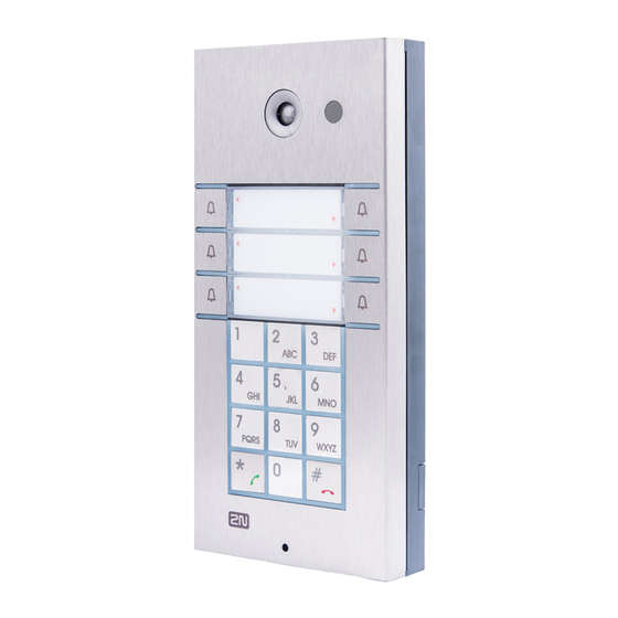
- Page 10 (C) Part No. 6 buttons 9137161(C)KU keypad control of one electric lock possibility of connecting card reader, extenders or information panel or additional switch available option with camera (C) 2N TELEKOMUNIKACE a.s., www.2n.cz 10/106...
- Page 11 Part No. 6 buttons 9137160(C)KDU graphic display keypad control of one electric lock possibility of connecting card reader, extenders or information panel or additional switch available option with camera (C) (C) = Integrated camera 2N TELEKOMUNIKACE a.s., www.2n.cz 11/106...
-
Page 12: Extending Modules
Extending Modules Part No. Extending module 9135181E 8 buttons Dimension of the module 100 x 210 x 29 mm Part No. Extending module 9135182E 16 buttons Dimension of the module 100 x 210 x 29 mm 2N TELEKOMUNIKACE a.s., www.2n.cz 12/106... - Page 13 Part No. Info panel 9135310E Backlit panel without buttons; used for insertion of a telephone directory, company logo, house number, etc. 2N TELEKOMUNIKACE a.s., www.2n.cz 13/106...
- Page 14 Info panel – name plate Replacing cover for four name tags. Helps you use a half of the extending module for insertion of a telephone directory, working hours, etc. Part No. 9135302E Spare double-button name plate 2N TELEKOMUNIKACE a.s., www.2n.cz 14/106...
- Page 15 All units can be surface mounted without needing any additional accessories. To make them even more robust and resistant, use a Vandal Resistant mask. Caution For flush or outdoor mounting you need to use the accessories; see the Mounting Accessories subsection. 2N TELEKOMUNIKACE a.s., www.2n.cz 15/106...
-
Page 16: Mounting Accessories
Wall hole: (110 x 220 x 50) ±5 mm Part No. 9135361E Wall mounting boxwith 1-module roof Roof dimensions: (129 x 240 x 41) mm (W x H x D) Wall hole: (110 x 220 x 50) ±5 mm 2N TELEKOMUNIKACE a.s., www.2n.cz 16/106... - Page 17 Dimensions: (203 x 218 x 60) mm (W x H x D) Part No. 9135352E Wall mounting boxwith 2-module frame Dimensions: (225 x 235 x 46) mm (W x H x D) Wall hole: (210 x 220 x 50) ±5 mm 2N TELEKOMUNIKACE a.s., www.2n.cz 17/106...
- Page 18 The box ® with frame (without roof) allows for installation of IP Vario in indoor applications so that the unit does not practically stick out (up to 1 mm). 2N TELEKOMUNIKACE a.s., www.2n.cz 18/106...
-
Page 19: Internal Units And Accessories
. On the panel’s display not only can you find out who is at the door, but also start a conversation with the visitor, open the lock or turn on the light in the entrance hall. 2N TELEKOMUNIKACE a.s., www.2n.cz 19/106... - Page 20 Part No. 91378382W ® Indoor Touch desk stand white 2N TELEKOMUNIKACE a.s., www.2n.cz 20/106...
-
Page 21: Voip Telephones
IP network. Touchscreen and keypad control. Part No. 91378358 Grandstream GXV3275 VoIP telephone GXV3275 is the successor to the popular GXV3175 model, which allows comfortable video calls in the IP network. Touchscreen control. 2N TELEKOMUNIKACE a.s., www.2n.cz 21/106... -
Page 22: Electric Locks
BEFO 11211MB with mechanical blocking 12 V / 230 mA DC low consumption Enables mechanically close or open the lock. When opened, the lock is open all the time. When closed, it behaves as standart electrical lock. 2N TELEKOMUNIKACE a.s., www.2n.cz 22/106... - Page 23 The failsafe lock is closed when electricity is switched on. When electricity is interrupted, the lock is opened. It contains a built-in contact to indicate whether the door is open or closed. FAQ: Electric locks – Difference between locks in 2N IP intercoms accesories 2N TELEKOMUNIKACE a.s., www.2n.cz 23/106...
-
Page 24: Power Supply
Part No. 91341481E Stabilised 12 V / 2 A power supply needs to be used when no PoE is available. Part No. 932928 For external power supply of the lock with 12 V AC voltage. 2N TELEKOMUNIKACE a.s., www.2n.cz 24/106... -
Page 25: Additional Modules
IP Vario intercom. Allows the use of EM4100, EM4102 and HID Proximity cards. Another two switches, two logical inputs and a Wiegand interface ® are available. It is compatible with all 2N IP Vario models. Part No. 9154004 Water-proof metal button (suitable for Internal RFID card reader) Part No. - Page 26 Wiegand Isolator ® Wiegand Isolator is designed for galvanic isolation of two devices separately power supplied and ® interconnected via the Wiegand bus. The 2N Wiegand Isolator protects the interconnected devices against communication errors and/or damage. Part No. 9137410E External IP Relay – 1 output...
- Page 27 (suitable for Internal RFID card reader or Security relay) A button for connection to a logic input for opening a door inside a building. Part No. 9159012 Magnetic door contact (suitable for Internal RFID card reader) 2N TELEKOMUNIKACE a.s., www.2n.cz 27/106...
- Page 28 (2 wires) from your original door bell or door intercom to connect any IP device. You don’t have to ® configure anything, and you only need one 2N 2Wire unit at each end of the cable and a power source connected to at least one of these units.
- Page 29 USB RFID card reader 125 kHz External RFID card reader for connection to a PC using a USB interface. Suitable for system management and the addition of EM41xx cards via the PC application, ® Access Commander 2N TELEKOMUNIKACE a.s., www.2n.cz 29/106...
- Page 30 NFC/HCE using a web interface or ® Access Commander application. It reads the same types of cards and devices as card readers in 2N IP intercoms ISO/IEC 14443A Mifare Classic 1k & 4k, DESFire EV1, Mini, Plus S&X, Ultralight, Ultralight C...
- Page 31 Use an external antenna with the induction loop, Part No. 9159050. A 170 cm long interconnecting cable is included. Part No. 916020 RJ-45 adapter For more accessories and particular advice please contact your local distributor of 2N products. 2N TELEKOMUNIKACE a.s., www.2n.cz 31/106...
-
Page 32: Terms And Symbols
Warning Always abide by this information to prevent damage to the device. Caution Important information for system functionality. Useful information for quick and efficient functionality. Note Routines or advice for efficient use of the device. 2N TELEKOMUNIKACE a.s., www.2n.cz 32/106... -
Page 33: Description And Installation
2. Description and Installation Here is what you can find in this section: 2.1 Before You Start 2.2 Mechanical Installation 2.3 Electric Installation 2.4 Completion 2.5 Extending Module Connection 2N TELEKOMUNIKACE a.s., www.2n.cz 33/106... -
Page 34: Product Completeness Check
Before you start please check whether the contents of the package of your new ® IP Vario complies with the following list. ® 1x 2N IP Vario 1x spare seal 1x drilling template 1x hexagonal wrench 1x spare name plate 1x terminal block plug 2x screw 2x dowel 2N TELEKOMUNIKACE a.s., www.2n.cz 34/106... -
Page 35: Mechanical Installation
® IP Vario surface Surface 1-module roof 9135331E or Surface 2- module roof 9135332E Outdoor, ® IP Vario flush mounting Wall mounting box with 1-module roof 9135361E or Wall mounting box with 2-module roof 9135362E 2N TELEKOMUNIKACE a.s., www.2n.cz 35/106... - Page 36 When the proper mounting instructions are not met, water might get in and destroy the electronics. It is because the intercom circuits are under continuous voltage and water infiltration causes an electro-chemical reaction. The manufacturer's warranty shall be void for products damaged in this way! 2N TELEKOMUNIKACE a.s., www.2n.cz 36/106...
-
Page 37: Surface Mounting
® 2. Use the hexagon key wrench included in the supply and remove the 2N IP Vario metal cover. Remove the screw in the lower part of the metal cover and fold out the cover. - Page 38 Carry the supply cables (Ethernet, lock, power cables) to the basic module box through one of the holes. Seal the screw hole carefully with some cement or non-aggressive silicone to avoid water infiltration. 2N TELEKOMUNIKACE a.s., www.2n.cz 38/106...
- Page 39 Make sure that the cables are not squeezed while installing the plastic cover. For the correct cable installation. ® 10.Remove the protective foil from the display (for display-equipped 2N IP Vario versions only). 11. Make sure that the cables are placed properly inside and that none of them obstructs a perfect cover closure.
- Page 40 19. Check whether a silicone seal is inserted in the top groove of the plastic cover. A spare seal package is included. 20. Close the metal cover and fix it with screws. 2N TELEKOMUNIKACE a.s., www.2n.cz 40/106...
-
Page 41: Outdoor Installation Rules
The product is not designed as a burglar protection device except when used in combination with a standard lock, which has the security function. 2N TELEKOMUNIKACE a.s., www.2n.cz 41/106... -
Page 42: Electric Installation
Part No. 91341481E. IP Vario is configured over an integrated administration web server, which can be controlled from any web browser, e.g., Mozilla Firefox. Video Tutorial: Door communication system 2N® IP Vario – Electrical Installation 2N TELEKOMUNIKACE a.s., www.2n.cz 42/106... -
Page 43: Description Of Printed Circuit Board Connectors
Ethernet connection is to be connected to the terminal block X2 as shown in table below. The terminal block can be removed from the PCB. The connection of each of the connectors is described in the subsections below. Description of Connectors, PCB Version 530v2 2N TELEKOMUNIKACE a.s., www.2n.cz 43/106... - Page 44 Description of Connectors, PCB Versions 535v1, 535v2 Description of Connectors, PCB Versions 535v5 2N TELEKOMUNIKACE a.s., www.2n.cz 44/106...
- Page 45 Description of Connectors, PCB Versions 535v8 2N TELEKOMUNIKACE a.s., www.2n.cz 45/106...
-
Page 46: Terminal Block X2 Connection
, disconnect it IP from the power supply. Then pull to remove the terminal block from the printed circuit board. Insert the wires under the respective terminals. Tighten the terminals using a flat screwdriver. Replace the terminal block to the printed circuit board. 2N TELEKOMUNIKACE a.s., www.2n.cz 46/106... -
Page 47: Ethernet Connection
7 and 8 and place them under terminal 5 of ® IP Vario Terminal Block Connections Caution We recommend the use of a LAN surge protection. We recommend the use of a shielded SSTP Ethernet cable. 2N TELEKOMUNIKACE a.s., www.2n.cz 47/106... -
Page 48: Electric Lock Connection
For this way of protection we recommend a diode 1A / 1000V (e.g., 1N4007, 1N5407, 1N5408) connected antiparallel to the device. 2N TELEKOMUNIKACE a.s., www.2n.cz 48/106... -
Page 49: External Power Supply Connection
Ethernet cable as shown in Tab. 1 above. Using a power adapter, Part No. 91341481E. The external power supply from a power adapter can be connected to terminals 1 and Terminal Block Connection for Power Adapter 2N TELEKOMUNIKACE a.s., www.2n.cz 49/106... -
Page 50: Configuration Connector Connection
Connection of Configuration Connector Jumpers Display Connector The display connector includes the name plate backlighting ON/OFF switching pins ® IP Vario resetting pins. The remaining pins are intended for display connection. 2N TELEKOMUNIKACE a.s., www.2n.cz 50/106... -
Page 51: Resetting Procedure (Version 535V5 And Earlier)
Remove the jumper from the resetting (default setting) position (put the display switch into the NORMAL position in the display-equipped models with 535v1 and 535v2 board versions). ® Switch IP Vario Configuration Jumpers on Display Connector 2N TELEKOMUNIKACE a.s., www.2n.cz 51/106... -
Page 52: Resetting Procedure (Version 535V8 And Later)
Press and hold the RESET button. Wait until the red and green LEDs on the device come on simultaneously (approx. 20 s). Release the RESET button. The device announces the current IP address via the loudspeaker connected automatically. 2N TELEKOMUNIKACE a.s., www.2n.cz 52/106... - Page 53 Release the RESET button. Caution In case of resetting the factory default settings on a device with a version of firmware 2.18 or higher it is necessary to reprogram the ® Security Relay using the instructions from section 2N TELEKOMUNIKACE a.s., www.2n.cz 53/106...
-
Page 54: Card Reader Connection
® IP Vario functions with an EM41XX RFID card reader, two relays for external load ® switching, two logical inputs and RS-485 and Wiegand interfaces. The current 2N Vario software version, however, supports the card reader and relays only. Caution ®... -
Page 55: Card Reader Mounting
Replace and screw back the metal cover. Grounding We recommend to ground the intercom in order to improve the static electricity resistance. For proper grounding you need a cable of the minimum cross-section of 4 mm2 and a cripm eye. 2N TELEKOMUNIKACE a.s., www.2n.cz 55/106... - Page 56 At the marked point push the nut genthly sliding it downwards. Insert a sufficiently long M3 screw, e.g. Push the screw down to make a gap for the crimp eye. At the marked point insert the crimped cable. Assemble the set and ground the cable. 2N TELEKOMUNIKACE a.s., www.2n.cz 56/106...
-
Page 57: Available Switches
Passive switch: NO and NC contacts, up to 30 V / 1 A AC/DC Card Reader (Card 125 kHz Reader) (Part No. 9137430 E) Relay 2 Passive switch: NO and NC contacts, up to 30 V / 1 A AC/DC (Card Reader) 2N TELEKOMUNIKACE a.s., www.2n.cz 57/106... - Page 58 If its bottom part is loose, the mounting wall is probably uneven. ® Support the corners to avoid IP Vario bending. Caution An improper mounting may significantly deteriorate the button function. A poor outdoor mounting may cause water in-leak and damage to the electronics. 2N TELEKOMUNIKACE a.s., www.2n.cz 58/106...
-
Page 59: Most Frequent Mounting Errors
Most Frequent Mounting Errors For illustration, a part of the plastic cover is removed in the figures below to reveal the sealed loudspeaker and the cover-seal touch point. The cross section plane is marked white for better orientation. 2N TELEKOMUNIKACE a.s., www.2n.cz 59/106... - Page 60 2N TELEKOMUNIKACE a.s., www.2n.cz 60/106...
-
Page 61: Extending Module Connection
(for connection of another, more remote unit). Be sure to maintain the correct orientation of the units and avoid connector mismatch to ensure a proper function of the device! Connection of One-Row-Button Extending Modules 2N TELEKOMUNIKACE a.s., www.2n.cz 61/106... -
Page 62: Maximum Count Of Extenders
The basic unit is always on the left. Extenders are chain-connected, i.e. each is linked with its neighbour. The cable cannot be driven through the box interconnecting holes until the boxes have been connected (see subsection 2.3 Mounting – Mechanical Installation). Connection of Two-Button-Row Extending Module 2N TELEKOMUNIKACE a.s., www.2n.cz 62/106... -
Page 63: Button Numbering - Whole-Button Sets
The extending modules must be connected mutually and with the basic unit by means of a formed piece supplied with the extending module!!! Button Numbering Button numbering – one-button with a whole-button set Button numbering – whole-button sets 2N TELEKOMUNIKACE a.s., www.2n.cz 63/106... -
Page 64: Button Numbering - Double-Button Set
Installing the info panel name plate, Part No. 9135311E, into any of the extending modules will not change the numbering system (the buttons on the info panel sides will remain functional). Connecting the info panel module, Part No. 9135310E, will result in omission of eight numbers. 2N TELEKOMUNIKACE a.s., www.2n.cz 64/106... -
Page 65: Additional Switch
Before installing the module, make sure that the current and voltage limits of the module will not be exceeded in your application (refer to the Technical Parameters chapter). In no case use this module for mains voltage switching! 2N TELEKOMUNIKACE a.s., www.2n.cz 65/106... -
Page 66: Module Mounting
Module mounting: Switch off the intercom before module installation. 2N TELEKOMUNIKACE a.s., www.2n.cz 66/106... -
Page 67: Module Settings
Module settings: Refer to the Configuration manual for 2N IP intercoms for details. Connection: Switch Connection Normally opened NO – C Normally closed NC – C 2N TELEKOMUNIKACE a.s., www.2n.cz 67/106... -
Page 68: Internal Rfid Card Reader 125 Khz
Card reader Compatible with EM4100 / EM4102 / HID® Prox RFID cards Working frequency: 125 KHz ® Minimum reading distance: 10 mm above IP Vario cover Relay outputs Switching contact 30V / 1A AC / DC 2N TELEKOMUNIKACE a.s., www.2n.cz 68/106... - Page 69 Connect the wires for the reader module interface(s) if necessary. Replace and fix the plastic cover using cross-head screws. Replace and screw back the metal cover. Module settings: Refer to the Configuration manual for 2N IP intercoms for details. Connection: 2N TELEKOMUNIKACE a.s., www.2n.cz 69/106...
-
Page 70: Security Relay
(outside the ® secured area) and the electric lock (inside the secured area). The 2N Security Relay includes a relay that can only be activated if the valid opening code is received from the intercom. -
Page 71: Installation
To the relay output with a serial external power supply. The device also supports a Departure button connected between the ‘PB’ and ‘- HeliosIP/IP Intercom’ terminals. Press the Departure button to activate the output for 5 seconds. 2N TELEKOMUNIKACE a.s., www.2n.cz 71/106... -
Page 72: Status Signalling
Configuration: ® Connect the Security Relay to the properly set intercom switch output; refer to the Configuration manual for 2N IP intercoms . Make sure that one LED at ® least on the Security Relay is on or blinking. ®... - Page 73 ® FAQ: 2N Security Relay – what it is and how to use it with 2N IP intercom? Video Tutorial: Door 2N IP intercoms – Security Relay Connection: 2N TELEKOMUNIKACE a.s., www.2n.cz 73/106...
-
Page 74: Wiegand Isolator
LED IN switched against GND on WIEGAND OUT side Open LED OUT switched against GND on WIEGAND IN side (up to 24 V / 50 5 to 16V / 10 mA power supply from Wiegand bus receiver side 500 V DC isolation strength 2N TELEKOMUNIKACE a.s., www.2n.cz 74/106... - Page 75 Connection: 2N TELEKOMUNIKACE a.s., www.2n.cz 75/106...
-
Page 76: Induction Loop
12 V power supply outlets to the B connector. Connect the special cable to the intercom and connect the power supply to the mains. You can place the mated A and B connectors into the 2N IP intercom cover. - Page 77 Output short-circuit resistance: unlimited time Frequency characteristics: 100 Hz – 5 KHz ±3 dB Temperature range: -20 - +50 °C Covering: IP65 (with round cable of 5–10 mm diameter) Dimensions: 144 x 100 x 31 mm Weight: 0.3 kg 2N TELEKOMUNIKACE a.s., www.2n.cz 77/106...
-
Page 78: Function And Use
3. Function and Use ® This section describes the basic and extending functions of the the 2N IP Vario product. Here is what you can find in this section: 3.1 Configuration 3.2 Intercom Control as Viewed by External User 3.3 Display-Equipped Intercom as Viewed by External User 3.4 Intercom Control as Viewed by Internal User... -
Page 79: Ip Address Retrieval
Wait for the second sound signal 1-button models: Press the quick dial button on the basic unit five times. 3-buttons models: Press the second quick dial button on the basic unit five 2N TELEKOMUNIKACE a.s., www.2n.cz 79/106... - Page 80 If the address is 0.0.0.0, it means that the intercom has not obtained the IP address from the DHCP server. Note Be sure to press the button sequence within thirty seconds after the sound signal for security reasons. Up to 2 s intervals are allowed between the presses. 2N TELEKOMUNIKACE a.s., www.2n.cz 80/106...
-
Page 81: Static Ip Address Setting
The inter-digit delay may be 2 s at most. The device will have the following network parameters after restart: IP address – 192.168.1.100 Network mask – 255.255.255.0 Default gateway – 192.168.1.1 2N TELEKOMUNIKACE a.s., www.2n.cz 81/106... -
Page 82: Dynamic Ip Address Setting
The 2, 1, 1, 2, 2, 3 sequence must be entered within 30 seconds after the first sound signal for security reasons. The inter-digit delay may be 2 s at most. ® IP Vario gets the IP address upon restart only if the DHCP server is configured properly. 2N TELEKOMUNIKACE a.s., www.2n.cz 82/106... -
Page 83: Mode Switching With 1-Button Models
The 15 times 1 sequence must be entered within 30 seconds after the first sound signal for security reasons. The inter-digit delay may be 2 s at most. The static IP address mode will be switched into the dynamic IP address mode and vice versa upon restart. 2N TELEKOMUNIKACE a.s., www.2n.cz 83/106... -
Page 84: Intercom Control As Viewed By External User
You can also hang up the call any time by pushing if the Hang-up by # button is enabled; refer to Intercom Configuration / Hardware / Keypad subsection of Configuration Manual. 2N TELEKOMUNIKACE a.s., www.2n.cz 84/106... -
Page 85: Incoming Call Answer And Reject
You can activate or deactivate a profile and define call routing to the telephone numbers assigned to the profile using the numeric keypad. For more details refer to the Intercom Configuration / Directory / Time Profiles subsection of Configuration Manual subsection. 2N TELEKOMUNIKACE a.s., www.2n.cz 85/106... - Page 86 Enter the profile activation or deactivation code using the numeric keypad and push for confirmation. A valid code is announced by acoustic signalling depending on the code type. An invalid code is announced by acoustic signalling 2N TELEKOMUNIKACE a.s., www.2n.cz 86/106...
- Page 87 Buttons 2, 4, 6 and 8 are cursor keys in the telephone directory mode. Buttons 3 and 6 are functional keys and initiate the action displayed in the right- hand and left-hand screen corners. 2N TELEKOMUNIKACE a.s., www.2n.cz 87/106...
-
Page 88: Advertisement Mode
IP Vario subsection. Push the quick dialling button 6 to move to the Telephone directory mode and the button to move to the Calling to number mode (only if the telephone function is enabled, see Miscellaneous 2N TELEKOMUNIKACE a.s., www.2n.cz 88/106... -
Page 89: Calling To Number
To dial and display the number to be called, use the numeric keypad and push for confirmation. Push the quick dialling button 6 to delete and re-enter the last- dialled number if necessary. 2N TELEKOMUNIKACE a.s., www.2n.cz 89/106... - Page 90 To retrieve a text, use the numeric keypad. The text to be searched is displayed in the centre of the status line. To delete the last character push the quick dialling button 3. Entering the text to be searched Selecting one of the contacts found 2N TELEKOMUNIKACE a.s., www.2n.cz 90/106...
-
Page 91: Status Information
Status Information ® In addition to the above described modes, the IP Vario display indicates various device statuses: Call being set up Ringing – outgoing call Call connected Call terminated Call set-up failure No response 2N TELEKOMUNIKACE a.s., www.2n.cz 91/106... - Page 92 Incoming call Door opened/unlocked 2N TELEKOMUNIKACE a.s., www.2n.cz 92/106...
-
Page 93: Intercom Control As Viewed By Internal User
Intercom Configuration / Services / Phone / Calls subsection of Configuration Manual). To prolong a call push the # button on your telephone any time. A short beep 10 s before the call end signals an automatic all termination. Calling to 2N ® IP Vario ® IP Vario allows to answer an incoming call too. - Page 94 Enter the profile activation or deactivation code using the numeric keypad and push for confirmation. A valid code is announced by acoustic signalling depending on the code type. An invalid code is announced by acoustic signalling 2N TELEKOMUNIKACE a.s., www.2n.cz 94/106...
-
Page 95: Maintenance
® IP Vario contains no environmentally harmful components. When the product's service life is exhausted and you would like to dispose of it please do so in accordance with applicable legal regulations. 2N TELEKOMUNIKACE a.s., www.2n.cz 95/106... - Page 96 3.6 Downloads Templates Nametags Software ® USB driver 1.0.6 ® IP Eye 1.1.4.0.19 ® Network Scanner 3.0.4 2N TELEKOMUNIKACE a.s., www.2n.cz 96/106...
-
Page 97: Technical Parameters
Codecs: G.711, G.729, G.722, L16/16kHz Camera Sensor: 1/4'' colour CMOS Resolution: 640 (H) x 480 (V) Picture frequency: Up to 30 snaps/s Sensitivity: 1.9 V/lux-sec (550 nm) Viewing angle: 55° (H), 39° (V) Focal length: 3.11 mm 2N TELEKOMUNIKACE a.s., www.2n.cz 97/106... - Page 98 Passive switch: NO and NC contacts, up to 30 V / 1 A AC/DC Active switch output: 10 up to 14 V DC depending on power supply (PoE: approx. 14 V; adaptor: same voltage as power supply), max 600 mA 2N TELEKOMUNIKACE a.s., www.2n.cz 98/106...
- Page 99 Storing temperature:−40 °C to 70 °C Dimensions: (210 x 100 x 29) mm Weight: 500 g Covering level: IP53 when the roof is used (see Mounting Accessories) IP50 when the roof is not used Resistance level: IK08 2N TELEKOMUNIKACE a.s., www.2n.cz 99/106...
-
Page 100: Supplementary Information
5. Supplementary Information Here is what you can find in this section: 5.1 Troubleshooting 5.2 Directives, Laws and Regulations 5.3 General Instructions and Cautions 2N TELEKOMUNIKACE a.s., www.2n.cz 100/106... -
Page 101: Troubleshooting
5.1 Troubleshooting For the most frequently asked questions refer to faq.2n.cz 2N TELEKOMUNIKACE a.s., www.2n.cz 101/106... -
Page 102: Directives, Laws And Regulations
Increase the separation between the equipment and receiver Connect the equipment into an outlet on a circuit different from that to which the receiver is connected Consult the dealer or an experienced radio/TV technician for help. 2N TELEKOMUNIKACE a.s., www.2n.cz 102/106... - Page 103 2N TELEKOMUNIKACE a. s. is not liable neither for any limitation of such a product’s functionality, nor for any damage, loss or injury relating to such a potential limitation of functionality.
-
Page 104: General Instructions And Cautions
The consumer shall, at its own expense, obtain software protection of the product. The manufacturer shall not be held liable and responsible for any damage incurred as a result of the use of deficient or substandard security software. 2N TELEKOMUNIKACE a.s., www.2n.cz 104/106... -
Page 105: Electric Waste And Used Battery Pack Handling
Make sure that the devices to be disposed of are complete. Do not throw battery packs into fire. Battery packs may not be taken into parts or short-circuited either. 2N TELEKOMUNIKACE a.s., www.2n.cz 105/106... - Page 106 2N TELEKOMUNIKACE a.s. Modřanská 621, 143 01 Prague 4, Czech Republic Phone: +420 261 301 500, Fax: +420 261 301 599 E-mail: sales@2n.cz Web: www.2n.cz v2.12 2N TELEKOMUNIKACE a.s., www.2n.cz 106/106...
Need help?
Do you have a question about the IP Vario and is the answer not in the manual?
Questions and answers