
Subscribe to Our Youtube Channel
Related Manuals for HIKVISION DS-2DP1618ZIXS-DE


Summary of Contents for HIKVISION DS-2DP1618ZIXS-DE
- Page 1 User Manual of PanoVu Series Network Camera PanoVu Series Network Camera User Manual...
- Page 2 User Manual of PanoVu Series Network Camera User Manual USE OF THIS PRODUCT, EVEN IF HIKVISION HAS BEEN COPYRIGHT © 2019 Hangzhou Hikvision Digital Technology ADVISED OF THE POSSIBILITY OF SUCH DAMAGES. Co., Ltd. REGARDING TO THE PRODUCT WITH INTERNET ACCESS, ALL RIGHTS RESERVED.
- Page 3 User Manual of PanoVu Series Network Camera harmonized European standards listed under the EMC Directive 2014/30/EU, the RoHS Warnings: Directive 2011/65/EU 2012/19/EU (WEEE directive): Products Please adopt the power adapter which can meet the marked with this symbol cannot be safety extra low voltage (SELV) standard.
- Page 4 User Manual of PanoVu Series Network Camera Please use the provided glove when open up the product cover. Do not touch the product cover with fingers directly, because the acidic sweat of the fingers may erode the surface coating of the product cover. ...
-
Page 5: Table Of Contents
User Manual of PanoVu Series Network Camera Table of Contents ABOUT THIS DOCUMENT ............................... 1 ................................1 VERVIEW OF ONTENTS ....................................1 OTICE CHAPTER 1 ACTIVATING AND ACCESSING TO THE CAMERA ....................2 ..............................2 YSTEM EQUIREMENT .............................. 2 CTIVATING THE AMERA 1.2.1 Setting the Camera over the LAN ........................ - Page 6 User Manual of PanoVu Series Network Camera 4.2.1 Configuring Basic PTZ Parameters ........................50 4.2.2 Configuring PTZ Limits ............................51 4.2.3 Configuring Initial Position ..........................52 4.2.4 Configuring Park Action ............................ 53 4.2.5 Configuring Privacy Mask for PTZ Camera Channel .................... 54 4.2.6 Configuring Scheduled Tasks ..........................
- Page 7 User Manual of PanoVu Series Network Camera ............................... 97 EOPLE ENSITY 6.5.1 Rule .................................. 97 6.5.2 Data Upload ..............................98 6.5.3 Advanced Configuration ............................ 99 6.5.4 Parameters ..............................100 ..............................100 MART ISPLAY CHAPTER 7 SYSTEM SETTINGS ............................101 ..............................101 ASIC NFORMATION 7.1.1...
-
Page 8: About This Document
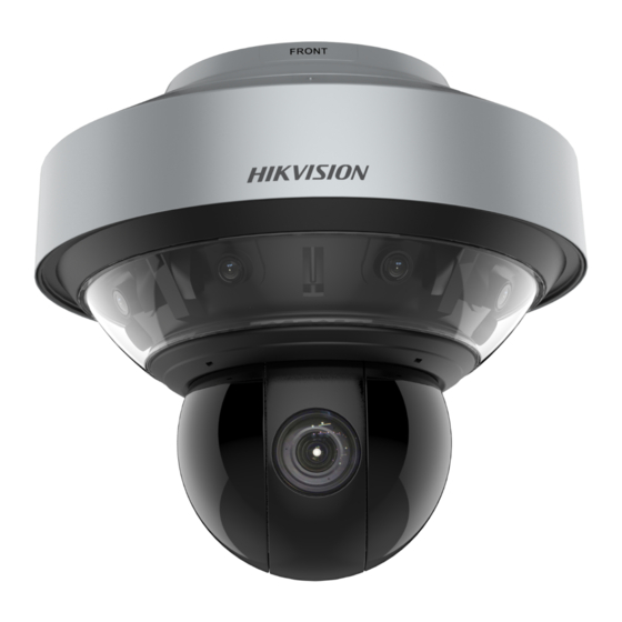
User Manual of PanoVu Series Network Camera About This Document This document introduces PanoVu series network camera, including 360° panoramic + PTZ camera, 270° panoramic + PTZ camera, 180° panoramic + PTZ camera, and 360° panoramic camera. It covers how to activate and access to the camera, and operate the camera in the network environment. -
Page 9: Chapter 1 Activating And Accessing To The Camera
User Manual of PanoVu Series Network Camera Chapter 1 Activating and Accessing to the Camera 1.1 System Requirement System requirements of web browser accessing are as follows: Operating System: Microsoft Windows 7 (32 bit/64 bit) and above version CPU: Intel Pentium IV 3.0 GHz or higher RAM: 1G or higher Display: 1024 ×... -
Page 10: Activating The Camera
User Manual of PanoVu Series Network Camera Network Cable Network Cable Network Camera Switch or Router Connecting via an Switch or a Router Figure 1-2 1.2.2 Activating the Camera Purpose: You are required to activate the camera first before you can use the camera. Activation via web browser, activation via SADP, and activation via client software are supported. - Page 11 User Manual of PanoVu Series Network Camera STRONG PASSWORD RECOMMENDED– We highly recommend you create a strong password of your own choosing (Using a minimum of 8 characters, including at least three of the following categories: upper case letters, lower case letters, numbers, and special characters.) in order to increase the security of your product.
- Page 12 User Manual of PanoVu Series Network Camera 5. Change the device IP address to the same subnet with your computer by either modifying the IP address manually or checking the Enable DHCP checkbox. Modify the IP Address Figure 1-5 6. Input the password and click Save to activate your IP address modification. ...
- Page 13 User Manual of PanoVu Series Network Camera Control Panel Figure 1-6 2. Click Device Management to enter the Device Management interface, as shown in the figure below. Device Management Interface Figure 1-7 3. Check the device status from the device list, and select an inactive device. 4.
- Page 14 User Manual of PanoVu Series Network Camera STRONG PASSWORD RECOMMENDED– We highly recommend you create a strong password of your own choosing (Using a minimum of 8 characters, including at least three of the following categories: upper case letters, lower case letters, numbers, and special characters.) in order to increase the security of your product.
-
Page 15: Setting The Camera Over The Wan (Optional)
User Manual of PanoVu Series Network Camera 1.3 Setting the Camera over the WAN (Optional) Purpose: This section explains how to connect the camera to the WAN with a static IP or a dynamic IP. 1.3.1 Static IP Connection Before you start: Apply a static IP from an ISP (Internet Service Provider). -
Page 16: Dynamic Ip Connection
User Manual of PanoVu Series Network Camera 1.3.2 Dynamic IP Connection Before you start: Apply a dynamic IP from an ISP. With the dynamic IP address, you can connect the camera to a modem or a router. Connecting the camera via a router ... -
Page 17: Accessing To The Camera
User Manual of PanoVu Series Network Camera Normal Domain Name Resolution Figure 1-13 Steps: 1. Apply a domain name from a domain name provider. 2. Configure the DDNS settings in the DDNS Settings interface of the camera. Refer to Section 2.2.1 Basic Settings - Configuring DDNS Settings for detailed configuration. -
Page 18: Accessing By Client Software
User Manual of PanoVu Series Network Camera 1.4.2 Accessing by Client Software The product CD contains the client software. You can view the live video and manage the camera with the client software. Follow the installation prompts to install the client software and. The configuration interface and live view interface of client software are shown below. -
Page 19: Power-Up Action
User Manual of PanoVu Series Network Camera 1.5 Power-up Action After the power is applied, the camera will perform self-test actions. It begins with lens actions and then pan and tilt movement. After the power-up self-test actions, the information shown in Figure 1-17 will be displayed on screen for 40 seconds. -
Page 20: Chapter 2 Setting Local Parameters And Network
User Manual of PanoVu Series Network Camera Chapter 2 Setting Local Parameters and Network 2.1 Configuring Local Parameters Note: The local configuration refers to the parameters of the live view and other operations using the web browser. Steps: 1. Enter the Local configuration interface: Configuration >... -
Page 21: Configuring Network Settings
User Manual of PanoVu Series Network Camera Record File Size: Select the packed size of manually recorded and downloaded video files. The size can be set to 256M, 512M or 1G. Save record files to: Set the saving path for the manually recorded video files. ... - Page 22 User Manual of PanoVu Series Network Camera TCP/IP Settings Figure 2-2 2. Configure the basic network settings, including the NIC Type, IPv4 or IPv6 Address, IPv4 or IPv6 Subnet Mask, IPv4 or IPv6 Default Gateway, MTU settings and Multicast Address. 3.
- Page 23 User Manual of PanoVu Series Network Camera the following categories: upper case letters, lower case letters, numbers, and special characters.) in order to increase the security of your product. Proper configuration of all passwords and other security settings is the responsibility of the installer and/or end-user.
- Page 24 User Manual of PanoVu Series Network Camera Configuring PPPoE Settings Purpose: If you have no router but only a modem, you can use Point-to-Point Protocol over Ethernet (PPPoE) function. Steps: 1. Enter the PPPoE settings interface: Configuration > Network > Basic Settings > PPPoE PPPoE Settings Figure 2-5 2.
- Page 25 User Manual of PanoVu Series Network Camera Port Settings Figure 2-6 HTTP port, RTSP port and port of the camera. Set the HTTP Port: The default port number is 80. The default port number is 554. RTSP Port: ...
-
Page 26: Advanced Settings
User Manual of PanoVu Series Network Camera To port mapping with the customized port numbers: Choose And you can customize the value of the port No. by yourself. Configure the Port No. Figure 2-7 4. Click to save the settings. 2.2.2 Advanced Settings Configuring SNMP Settings Purpose:... - Page 27 User Manual of PanoVu Series Network Camera SNMP Settings Figure 2-8 2. Check the corresponding version checkbox (Enable SNMP v1, Enable SNMP v2c, Enable SNMP v3) to enable the feature. 3. Configure the SNMP settings. Note: The configuration of the SNMP software should be the same as the settings you configure here. 4.
- Page 28 User Manual of PanoVu Series Network Camera FTP Settings Figure 2-9 2. Input the FTP address and port. Note: The server address supports both the domain name and IP address formats. 3. Configure the FTP settings. The user name and password are required for the FTP server login. ...
- Page 29 User Manual of PanoVu Series Network Camera Picture Name: Set the naming rule for captured picture files. You can choose Default in the drop-down list to use the default rule, that is, IP address_channel number_capture time_event type.jpg (e.g., 10.11.37.189_01_20150917094425492_FACE_DETECTION.jpg) Or you can customize it by adding a Custom Prefix to the default naming rule. 5.
- Page 30 User Manual of PanoVu Series Network Camera E-mail Encryption: Email encryption can be selected among None, SSL, and TLS. When you select SSL or TLS and disable STARTTLS, e-mails will be sent after encrypted by SSL or TLS. The SMTP port should be set as 465 for this encryption method.
- Page 31 User Manual of PanoVu Series Network Camera Create Certificate Figure 2-13 OPTION 1: Create the self-signed certificate 1) Select Create Self-signed Certificate. 2) Click Create to create the following dialog box. Create Self-signed Certificate Figure 2-14 3) Input the country, host name/IP, validity and other information. 4) Click OK to save the settings.
- Page 32 User Manual of PanoVu Series Network Camera Note: You can click configure the HTTPS port No. on your demand; refer Section 2.2.1 Basic Settings - Configuring Port Settings for details. 4. Check the Enable HTTPS checkbox and click Save. Configuring QoS Settings Purpose: QoS (Quality of Service) can help solve the network delay and network congestion by configuring the priority of data sending.
- Page 33 User Manual of PanoVu Series Network Camera Before connecting the network camera to the protected LAN, apply a digital certificate from a Certificate Authority. The network camera requests access to the protected LAN via the authenticator (a switch). The switch forwards the identity and password to the authentication server (RADIUS server).
- Page 34 User Manual of PanoVu Series Network Camera Check the Enable ***CGI checkbox and then select the authentication from the drop-down list. Then you can access to the camera through the third party platform. ONVIF Steps: 1. Check the Enable ONVIF checkbox to enable the function. 2.
-
Page 35: Chapter 3 Live View
User Manual of PanoVu Series Network Camera Chapter 3 Live View 3.1 Install the Plug-in Install the plug-in before viewing the live video and operating the camera. Follow the installation prompts to install the plug-in. Figure 3-1 Download and Install Plug-in Notes: ... -
Page 36: Live View Page
User Manual of PanoVu Series Network Camera 3.2 Live View Page 3.2.1 Descriptions of the live view page: Figure 3-2 Live View Page Menu Bar: Click each tab to enter Live View, Playback, Picture, and Configuration page respectively. Click to display the help file of the camera. Click to logout the system. - Page 37 User Manual of PanoVu Series Network Camera Starting Live View Click on the toolbar to start the live view of all channels of the network camera. Live view page of panoramic + PTZ camera and panoramic camera are different as shown below. Start Live View (Panoramic + PTZ Camera) Figure 3-3 Descriptions of Icons on Toolbar and Live View Interface are listed below:...
- Page 38 User Manual of PanoVu Series Network Camera stream and sub stream. The default setting of stream type is Plug-in Switch Click to select between and play the live video via player Webcomponents or Quick Time. The live video is played via webcomponents by default, and other types of players are supported for the browser, such as MJPEG, and VLC.
- Page 39 User Manual of PanoVu Series Network Camera Focus Click , the lens focus far and the items far away gets clear. Click , the lens focus near and the items nearby gets clear. Iris When the image is too dark, click to open the iris.
-
Page 40: Configuring Image Settings
User Manual of PanoVu Series Network Camera Hold down the left mouse button and drag the mouse to the lower right on the live video. The corresponding position will be moved to the center of the live video and zoomed in. - Page 41 User Manual of PanoVu Series Network Camera Display Settings Figure 3-5 Image Adjustment Brightness This feature is used to adjust brightness of the image. The value ranges from 0 to 100. Contrast This feature enhances the difference in color and light between parts of an image. The value ranges from 0 to 100.
- Page 42 User Manual of PanoVu Series Network Camera Manual Iris Figure 3-6 Shutter Priority: The value of shutter needs to be adjusted manually. The iris and gain values will be adjusted automatically according to the brightness of the environment. Manual Shutter Figure 3-7 ...
- Page 43 User Manual of PanoVu Series Network Camera The camera focuses automatically at any time according to objects in the scene. Semi-auto: The camera focuses automatically only once after panning, tilting and zooming. Manual: In Manual mode, you need to use on the control panel to focus manually.
- Page 44 User Manual of PanoVu Series Network Camera For detailed parameters configuration of IR light, you can enter the OSD menu by calling the special preset 95. When the IR Light Mode is auto, the day/night mode is adjusted automatically according to the IR Light Mode.
- Page 45 User Manual of PanoVu Series Network Camera Outdoor You can select this mode when the camera is installed in outdoor environment. Indoor You can select this mode when the camera is installed in indoor environment. Fluorescent Lamp You can select this mode when there are fluorescent lamps installed near the camera.
-
Page 46: Configuring Osd Settings
User Manual of PanoVu Series Network Camera Capture Mode: The Capture Mode can be selected from the list. Other Lens Initialization The lens operates the movements for initialization when you check the Lens Initialization checkbox. Zoom Limit You can set Zoom Limit value to limit the maximum value of zooming. -
Page 47: Configuring Text Overlay Settings
User Manual of PanoVu Series Network Camera 5. You can use the mouse to drag the text frame IPdome in the live view window to adjust the OSD position. 6. In Text Overlay, you can custom 8 more text. Check the checkbox, and the corresponding text will be displayed on live image. -
Page 48: Configuring Privacy Mask For Panoramic Camera Channel
User Manual of PanoVu Series Network Camera Text Overlay Settings Figure 3-17 3.3.4 Configuring Privacy Mask for Panoramic Camera Channel Purpose: Privacy Mask enables you to cover certain areas on the live video to prevent certain spots in the surveillance area from being live viewed and recorded. Note: This function is supported by certain camera models. - Page 49 User Manual of PanoVu Series Network Camera Configure Video Settings Figure 3-18 2. Select the Stream Type of the camera to Main Stream (Normal), Sub-Stream or Third Stream. Note: The main stream is usually for recording and live viewing with good bandwidth, and the sub-stream can be used for live viewing when the bandwidth is limited.
-
Page 50: Configuring Audio Settings
User Manual of PanoVu Series Network Camera SVC: SVC is a video encoding technology. It extracts frames from the original video and sends these frames to a video recorder which also supports SVC function when the network bandwidth is insufficient. Smoothing: Drag to adjust the value of video smoothing on your demand. - Page 51 User Manual of PanoVu Series Network Camera Region of Interest(1) Figure 3-19 Region of Interest (2) Figure 3-20 Stream Type: You can set the ROI function for main stream, sub-stream and third stream. Select a stream type and then configure the ROI settings. Fixed Region: The fixed region encoding is the ROI encoding for the manually configured area.
-
Page 52: Target Cropping
User Manual of PanoVu Series Network Camera 4. Click , and then drag the mouse to draw the region of interest on the live video. 5. Adjust the ROI level from 1 to 6. The higher the value, the better image quality in the red frame. 6. -
Page 53: Chapter 4 Ptz Control
User Manual of PanoVu Series Network Camera Chapter 4 PTZ Control 4.1 Operating PTZ Control Purpose: In the live view interface, you can use the PTZ control buttons to control panning, tilting and zooming. Refer to Section 3.2.2 Live View Operation for detailed information. 4.1.1 Setting/Calling a Preset Purpose: A preset is a predefined image position. - Page 54 User Manual of PanoVu Series Network Camera Calling a Preset Figure 4-2 For convenient preset selection, refer to the following steps to navigate to the preset you want. Steps: 1. Select any preset from the list. 2. Click the preset number you need on the keyboard. Note: The following presets are predefined with special commands.
-
Page 55: Setting/Calling A Patrol
User Manual of PanoVu Series Network Camera Note: You may need to use the OSD (On Screen Display) menu when controlling the camera remotely. To display the OSD menu on the live view screen, you can call the preset number 95. 4.1.2 Setting/Calling a Patrol Purpose: A patrol is a memorized series of preset function. -
Page 56: Setting/Calling A Pattern
User Manual of PanoVu Series Network Camera Calling a Patrol Figure 4-5 4.1.3 Setting/Calling a Pattern Purpose: A pattern is a memorized series of pan, tilt, zoom, and preset functions. It can be called on the pattern settings interface. There are up to 4 patterns for customizing. ... -
Page 57: Ptz Configuration
User Manual of PanoVu Series Network Camera 4.2 PTZ Configuration 4.2.1 Configuring Basic PTZ Parameters Purpose: You can configure the basic PTZ parameters, including proportional pan, preset freezing, preset speed, etc. 1. Enter the Basic PTZ parameter configuration interface: Configuration > PTZ > Basic Settings Basic PTZ Configuration Interface Figure 4-7 2. -
Page 58: Configuring Ptz Limits
User Manual of PanoVu Series Network Camera Non-motor Vehicle: Choose the Non-motor Vehicle when you monitor the non-motor vehicles. Motor Vehicle: Choose the Motor Vehicle when you monitor the motor vehicles. Auto: You are recommended to set it to be auto when the application scene of the camera is complicated. -
Page 59: Configuring Initial Position
User Manual of PanoVu Series Network Camera Configure the PTZ Limit Figure 4-8 2. Click the Enable Limit checkbox and choose the limit type as manual stops or scan stops. Manual Stops: When manual limit stops are set, you can operate the PTZ control panel manually only in the limited surveillance area. -
Page 60: Configuring Park Action
User Manual of PanoVu Series Network Camera PTZ Configuration Figure 4-9 2. Click the PTZ control buttons to find a position as the initial position of the camera; you can also call a defined preset and set it as the initial position of the camera. 3. -
Page 61: Configuring Privacy Mask For Ptz Camera Channel
User Manual of PanoVu Series Network Camera Action Types Figure 4-11 5. Click to save the settings. 4.2.5 Configuring Privacy Mask for PTZ Camera Channel Purpose: Privacy mask enables you to cover certain areas on the live video to prevent certain spots in the surveillance area from being live viewed and recorded. -
Page 62: Configuring Scheduled Tasks
User Manual of PanoVu Series Network Camera Click to save the privacy mask, and it will be listed in the Privacy Mask List area; set the value of Active Zoom Ratio on your demand, and then the mask will only appear when the zoom ratio is greater than the predefined value. - Page 63 User Manual of PanoVu Series Network Camera Configure Scheduled Tasks Figure 4-15 2. Check the Enable Scheduled Task checkbox. 3. Set the Park Time. You can set the park time (a period of inactivity) before the camera starts the scheduled tasks. 4.
-
Page 64: Clearing Ptz Configurations
User Manual of PanoVu Series Network Camera Edit the Schedule and Task Type Figure 4-17 7. After setting the record schedule, you can click a record segment to display the segment record settings interface to edit the segment record parameters. (Optional) Segment Record Settings Figure 4-18 :... -
Page 65: Configuring Panorama Tracking
User Manual of PanoVu Series Network Camera The camera can be controlled by network and RS-485 signals. You can set the control priority of these two signals. The operation of Operator is prior to that of User. When the Operator is controlling the camera, the User cannot control it. - Page 66 User Manual of PanoVu Series Network Camera 2. Check the Enable Tracking checkbox to enable panorama tracking function. 3. Select the calibration mode and perform the calibration. Auto Calibration: (1) Select the calibration mode as Auto. (2) Select mode for auto calibration: One-Touch Calibration and Single Scene Calibration. ...
-
Page 67: Rapid Focus
User Manual of PanoVu Series Network Camera Up to 12 calibration points are supported for each scene. At least 4 points should be configured. More calibration points can increase the rate for successful calibration. Scatter the calibration points evenly in live view image for better calibration effect. 4. -
Page 68: Chapter 5 Storage And Playback
User Manual of PanoVu Series Network Camera Chapter 5 Storage and Playback : Notes In this and the following chapters, operation of the camera by the web browser will be taken as an example. You can set recording and capture schedule for different channels of the camera. Refer to the actual configuration interface. -
Page 69: Hdd Management
User Manual of PanoVu Series Network Camera the following categories: upper case letters, lower case letters, numbers, and special characters.) in order to increase the security of your product. Proper configuration of all passwords and other security settings is the responsibility of the installer and/or end-user. -
Page 70: Configuring Record Schedule
User Manual of PanoVu Series Network Camera Quota Settings Figure 5-4 Note: Up to 8 NAS disks can be connected to the camera. 5.1.3 Configuring Record Schedule Before you start: Make sure a local memory card is inserted in the camera or the network storage is added to the camera. - Page 71 User Manual of PanoVu Series Network Camera Record Parameters Figure 5-6 Pre-record: The time you set to start recording before the scheduled time or the event. For example, if an alarm triggers recording at 10:00, and the pre-record time is set as 5 seconds, the camera starts to record at 9:59:55.
- Page 72 User Manual of PanoVu Series Network Camera If you select Continuous, the video will be recorded automatically according to the time of the schedule. Record Triggered by Motion Detection If you select Motion, the video will be recorded when the motion is detected. Besides configuring the recording schedule, you have to set the motion detection area and check the Trigger Channel checkbox in the Linkage Method of Motion Detection settings interface.
-
Page 73: Configuring Capture Schedule
User Manual of PanoVu Series Network Camera 5.1.4 Configuring Capture Schedule Purpose: You can configure the scheduled snapshot and event-triggered snapshot. The captured picture can be stored in the local storage or network storage. Steps: 1. Enter the Capture settings interface: Configuration >... -
Page 74: Cloud Storage
User Manual of PanoVu Series Network Camera 10. Click to save the settings. 5.1.5 Cloud Storage Purpose: The captured pictures can be saved on Cloud Storage when the function is configured. Note: Cloud storage function varies according to different camera models. Steps: 1. -
Page 75: Playback
User Manual of PanoVu Series Network Camera 3. Select one picture and click Preview to preview the picture. 4. Check the checkbox in front of the files that you need to download. 5. Click to download the files. Note: Configure the saving path from Configuration > Local Configuration >Save snapshots in live view. 5.3 Playback Purpose: This section explains how to view the remotely recorded video files stored in the memory card or... - Page 76 User Manual of PanoVu Series Network Camera 3. Click to play the video files found on this date. The toolbar on the bottom of Playback interface can be used to control playing process. Playback Toolbar Figure 5-13 Descriptions of Icons on PTZ Control Panel are listed below: Playback Click to start playback and the icon turns into...
-
Page 77: Downloading Video Files
User Manual of PanoVu Series Network Camera The different colors of the video on the progress bar stand for the different video types as shown in Figure 5-16. Video Types Figure 5-16 5.3.2 Downloading Video Files Steps: 1. Click on the playback interface. The pop-up menu is shown in Figure 5-17. 2. -
Page 78: Chapter 6 Events Settings
User Manual of PanoVu Series Network Camera Chapter 6 Events Settings Purpose: This section explains how to configure the camera to respond to alarm events, including motion detection, video tampering, video loss, alarm input, alarm output, exception, and audio exception detection. - Page 79 User Manual of PanoVu Series Network Camera Motion Detection Settings-Normal Figure 6-1 Expert Motion Detection Settings-Expert Figure 6-2 Steps: (1) Set the Scheduled Image Settings, there are OFF, Auto-Switch and Scheduled-Switch selectable. If the switch mode is enabled, you can configure the detection rule for the day and night separately.
- Page 80 User Manual of PanoVu Series Network Camera Scheduled-Switch: Switch to the day mode at 6:00 a.m., and switch to the night mode at 18:00 p.m. (2) Select Area to configure in the dropdown list. (3) Set the values of Sensitivity. Sensitivity: The greater the value is, the easier the alarm will be triggered.
- Page 81 User Manual of PanoVu Series Network Camera Segment Arming Settings Figure 6-5 (5) Click to save the settings. Note: The time of each period cannot be overlapped. Up to 8 periods can be configured for each day. 6. Set the Alarm Actions for Motion Detection. Click tab to enter the Linkage Method interface.
-
Page 82: Configuring Video Tampering Alarm
User Manual of PanoVu Series Network Camera Trigger Recording Record a video when an event occurs. Note: You have to set the recording schedule to realize this function. Refer to Section 5.1 Storage Settings for settings the recording schedule. ... -
Page 83: Configuring Alarm Input
User Manual of PanoVu Series Network Camera 5. Click tab to select the linkage method taken for the video loss alarm. Send Email, Notify Surveillance Center, and Trigger Alarm Output are selectable. Refer to Step 6 in Section 6.1.1 Configuring Motion Detection. 6. -
Page 84: Configuring Alarm Output
User Manual of PanoVu Series Network Camera Linkage Method Figure 6-9 6.1.4 Configuring Alarm Output Steps: 1. Enter the Alarm Output settings interface: Configuration> Event > Basic Event > Alarm Output 2. Select one alarm output channel in the Alarm Output dropdown list. 3. -
Page 85: Handling Exception
User Manual of PanoVu Series Network Camera 6. You can copy the settings to other alarm outputs. 7. Click to save the settings. 6.1.5 Handling Exception The exception type can be HDD full, HDD error, network disconnected, IP address conflicted and illegal login to the cameras. - Page 86 User Manual of PanoVu Series Network Camera Note: This function is only supported by certain camera models. Steps: 1. Enter the audio exception detection interface: Configuration > Event > Smart Event > Audio Exception Detection Audio Exception Detection Figure 6-12 2.
-
Page 87: Configuring Intrusion Detection
User Manual of PanoVu Series Network Camera 6.2.2 Configuring Intrusion Detection Intrusion detection can set an area in the surveillance scene and once the area is entered, a set of alarm action is triggered. Steps: 1. Enter the intrusion detection interface: Configuration >... -
Page 88: Configuring Line Crossing Detection
User Manual of PanoVu Series Network Camera configuration is the same as the settings of the arming schedule for motion detection. Refer to Step 5 in Section 6.1.1 Configuring Motion Detection. 7. Click tab to select the linkage method taken for intrusion detection, Notify Surveillance Center, Send Email, Upload to FTP/Memory Card/NAS, Trigger Alarm Output and Trigger Recording are selectable. -
Page 89: Configuring Region Entrance Detection
User Manual of PanoVu Series Network Camera selectable. Sensitivity: Range [1-100]. The value of the sensitivity defines the size of the object which can trigger the alarm, when the sensitivity is high, a very small object can trigger the alarm. ... -
Page 90: Configuring Region Exiting Detection
User Manual of PanoVu Series Network Camera 5. Click on the live video to specify the four vertexes of the detection region, and right click to complete drawing. Repeat the step to configure other regions. You can click the button to clear all pre-defined regions. -
Page 91: Configuring Unattended Baggage Detection
User Manual of PanoVu Series Network Camera 4. Click the button to start the region drawing. 5. Click on the live video to specify the four vertexes of the detection region, and right click to complete drawing. Repeat the step to configure other regions. Up to 4 regions can be set. You can click the button to clear all pre-defined regions. -
Page 92: Configuring Object Removal Detection
User Manual of PanoVu Series Network Camera 3. The event triggered and park action related PTZ movement will be locked for 180 seconds after you enter the unattended baggage detection interface. Optionally, you can click the button to manually activate the movement, or lock the movement when the button turns to by clicking it. - Page 93 User Manual of PanoVu Series Network Camera Figure 6-18 Configuring Object Removal Detection Steps: 1. Enter the Object Removal Detection settings interface: Configuration> Event > Smart Event> Object Removal Detection 2. Check the checkbox of Enable to enable the Object Removal Detection function. 3.
-
Page 94: Behavior Analysis
User Manual of PanoVu Series Network Camera 9. Click tab to select the linkage method taken for the object removal alarm, Notify Surveillance Center, Send Email, Upload to FTP, Trigger Channel, Smart Tracking and Trigger Alarm Output are selectable. Refer to Section 6.1.1 Configuring Motion Detection for more details. Click button to save the settings. -
Page 95: Shield Region
User Manual of PanoVu Series Network Camera 3. Set the Snapshot: You can check the checkbox to upload JPEG image to surveillance center when VCA alarm occurs. You can also set the quality of the picture. 4. Click to save the settings. - Page 96 User Manual of PanoVu Series Network Camera Figure 6-21 Draw Line 4) Click the dropdown list in the rule list to select the crossing direction. Figure 6-22 Select Crossing Direction 5) Enable rules: Check the Enable checkbox of each rule in the rule list to enable the rule. 6) Click to save the settings.
- Page 97 User Manual of PanoVu Series Network Camera Click on the tool bar of the live view panel. Click the mouse on the live view panel. Right click the mouse to finish drawing. Figure 6-24 Draw Area 4) Set the duration from 1to 100. 5) Enable rules: Check the Enable checkbox of each rule in the rule list to enable the rule.
- Page 98 User Manual of PanoVu Series Network Camera Figure 6-26 Draw Area 4) Enable rules: Check the Enable checkbox of each rule in the rule list to enable the rule. 5) Click to save the settings. Region Exiting Purpose: This function can be used for detecting people, vehicles and objects exiting the pre-defined region. The alarm will be triggered if the rule is broken.
-
Page 99: Advanced Configuration
User Manual of PanoVu Series Network Camera Figure 6-28 Draw Area 4) Enable rules: Check the Enable checkbox of each rule in the rule list to enable the rule. 5) Click to save the settings. 4. Click Save to save the settings. 5. -
Page 100: Face Capture
User Manual of PanoVu Series Network Camera 4) Click Save to save the settings. 4. Click to save the settings. 6.4 Face Capture Face capture function detects and captures faces in surveillance scenes. When the grading of the detected face exceeds an algorithm-defined value, the PTZ camera channel captures the face and triggers linkage actions. -
Page 101: Rule
User Manual of PanoVu Series Network Camera Display on Picture: Check the checkbox, then there will be a frame on the target on the uploaded alarm picture if the checkbox is checked. Snapshot Settings: You can set the quality and resolution for the captured picture. ... -
Page 102: Advanced Configuration
User Manual of PanoVu Series Network Camera (1) Select a Detection Scene from the dropdown list. (2) Adjust the live image to a desired scene. you can use PTZ control panel or click to locate a scene with a face. Click Lock to lock PTZ for further settings. (3) Click and draw detection area on live image. - Page 103 User Manual of PanoVu Series Network Camera Advanced Face Capture Parameters Figure 6-33 Following parameters can be configured on this interface: Generation Speed: The speed to identify a target can be set by adjusting the slider, ranging from 1 to 5.
-
Page 104: People Density
User Manual of PanoVu Series Network Camera Restore Default: Click to restore all the settings in advanced configuration to the factory default. 6.5 People Density This function can detect the level of people density in the configured area. 6.5.1 Rule Purpose: Set up detection areas, density levels and linkage method on this page. -
Page 105: Data Upload
User Manual of PanoVu Series Network Camera 3. Set Density Level, including Number of People. Three levels can be configured in total, and the density increases from level 1 to level 3. Note: The number you input means the lower limit of each level. For example, set the Number of People of Level 1 as 10, Level 2 is 100, and level 3 is 1000. -
Page 106: Advanced Configuration
User Manual of PanoVu Series Network Camera 1. Check Enable Data Uploading checkbox, and the data of people density detection will be uploaded to surveillance center. 2. Check Enable Picture Uploading checkbox, the alarm will be uploaded to surveillance center with pictures. -
Page 107: Parameters
User Manual of PanoVu Series Network Camera 6.5.4 Parameters Check the version of people gathering density algorithms library on this page. 6.6 Smart Display Click Smart Display to display captured pictures in face capture function. Note: The function requires the support of camera and certain web browser. Adjust your browser settings according to the pop-up notification. -
Page 108: Chapter 7 System Settings
User Manual of PanoVu Series Network Camera Chapter 7 System Settings 7.1 Basic Information 7.1.1 Viewing Basic Information Enter the Basic Information interface: Configuration > System > System Settings > Basic Information In the Basic Information interface, you can edit the Device Name and Device No. Other information of the camera, such as Model, Serial No., Firmware Version, Encoding Version, Web Version, Plugin Version, Number of Channels, Number of HDDs, Number of Alarm Input and Number of Alarm Output are displayed. - Page 109 User Manual of PanoVu Series Network Camera Time Settings Figure 7-2 Configuring Time Synchronization by NTP Server Steps: (1) Check the radio button to enable the NTP function. (2) Configure the following settings: Server Address: IP address of NTP server. NTP Port: Port of NTP server.
-
Page 110: Configuring Rs-485
User Manual of PanoVu Series Network Camera You can also check the Sync. with computer time checkbox to synchronize the time of the camera with the time of your computer. Time Sync Manually Figure 7-4 Select the Time Zone Purpose: When the camera is taken to another time zone, you can use the Time Zone function to adjust the time. -
Page 111: Configuring Dst (Daylight Saving Time)
User Manual of PanoVu Series Network Camera Note: The Baud rate, PTZ Protocol and PTZ Address parameters of the camera should be exactly the same as those of the control device. 7.1.4 Configuring DST (Daylight Saving Time) Purpose: If there is the habit of adjusting clocks forward in your country in certain time period of a year, you can turn this function on. -
Page 112: Open Source Software
User Manual of PanoVu Series Network Camera Image Stitching Interface Figure 7-8 5. Configure the following settings: Encoder Track: Stream can be divided into several tracks in order to make up for the deficiency of decoder. 1 track and 3 tracks are selectable, and it is recommended to select 3, when the decoder is in poor performance. - Page 113 User Manual of PanoVu Series Network Camera Restoring Default Settings Steps: 1. Enter the Maintenance interface: Configuration > System > Maintenance > Upgrade & Maintenance: 2. Click to restore the default settings. Note: Clicking button will restore all the parameters to default settings including the IP address and user information.
-
Page 114: Log Searching
User Manual of PanoVu Series Network Camera Firmware: when you select Firmware, you need to find the firmware in your computer to upgrade the device. Firmware Directory: You need to find the directory where the firmware locates. The device can find the firmware in the directory automatically. -
Page 115: System Service
User Manual of PanoVu Series Network Camera 2. Set the log search conditions to specify the search, including the Major Type, Minor Type, Start Time and End Time as shown in Figure 7-12. 3. Click to search log files. The matched log files will be displayed on the Log List. 4. -
Page 116: Configuring Ip Address Filter
User Manual of PanoVu Series Network Camera Steps: 1. Enter the Authentication interface: Configuration> System> Security > Authentication 2. Select the authentication type. Digest is the recommended safer authentication way. 3. Click to save the settings. 7.3.2 Configuring IP Address Filter Purpose: With this function on, the camera allows certain IP addresses whether to log in or not. -
Page 117: Configuring Security Service
User Manual of PanoVu Series Network Camera Add an IP Figure 7-15 (3) Click OK to finish adding. Modify an IP Address Steps: (1) Left-click an IP address from filter list and click Modify. (2) Modify the IP address in the text filed. Modify an IP Figure 7-16 (3) Click OK to finish modifying. -
Page 118: Online User
User Manual of PanoVu Series Network Camera The administrator can add, delete or modify user accounts, and grant them different permissions. We highly recommend administrator to manage the device accounts and user permissions properly. Up to 31 user accounts can be created. Administrator need to input correct admin password when changing settings of other operators or users. -
Page 119: Appendix
User Manual of PanoVu Series Network Camera Appendix Appendix 1 SADP Software Introduction Description of SADP SADP (Search Active Devices Protocol) is a kind of user-friendly and installation-free online device search tool. It searches the active online devices within your subnet and displays the information of the devices. - Page 120 User Manual of PanoVu Series Network Camera You can click on each column heading to order the information; you can click to expand the device table and hide the network parameter panel on the right side, or click to show the network parameter panel. ...
-
Page 121: Appendix 2 Statics, Interference Lightning And Surge Protection
User Manual of PanoVu Series Network Camera Appendix 2 Statics, Interference Lightning and Surge Protection This product adopts TVS plate lightning protection technology to avoid damage caused by pulse signal that is below 3000V, like instantaneous lighting stroke, surging, etc. According to the actual outdoor situation, necessary protection measures must be taken, besides ensuring the electrical safety. - Page 122 User Manual of PanoVu Series Network Camera Power Power Display Power supply board Power supply board Video cable Operating center Control line Keyboard Cement pole/wall 1.5m underground Figure A.3.2 Grounding in Cement Pole/Wall Installation Notes: Because the signal transmission media of fiber optical camera and camera are isolated from the control center, they must be grounded locally to protect camera against damages.
- Page 123 User Manual of PanoVu Series Network Camera Grounding for Metal Pole Installation: When the camera is installed in environment where is conductive to the earth, e.g., metal pole, then the grounding of camera can be achieved by the properly grounded metal pole, meanwhile, the control center must be grounded locally as well.
-
Page 124: Appendix 3 Waterproof
User Manual of PanoVu Series Network Camera Appendix 3 Waterproof Notes: The long-arm wall mount is recommended for the outdoor application of camera. You cannot use the short-arm wall mount or pendant mount for outdoor application, because it is not water-proof. -
Page 125: Appendix 4 Bubble Maintenance
User Manual of PanoVu Series Network Camera Appendix 4 Bubble Maintenance The bubble is a transparent plastic. The dust, oil and finger print, etc. will cause scratch or image blur. Refer to the following method to clean the bubble. Handling dust Use oil free soft brush or blowing dust ball to clean the dust. -
Page 126: Appendix 5 Rs-485 Bus Connection
User Manual of PanoVu Series Network Camera Appendix 5 RS-485 Bus Connection General Property of RS-485 Bus According to RS-485 industry bus standard, RS-485 is a half-duplex communication bus which has 120Ω characteristic impendence, the maximum load ability is 32 payloads (including controller device and controlled device). - Page 127 User Manual of PanoVu Series Network Camera Controller Figure A.6.3 Star Shape Connection For such case, the best way is adding a RS-485 distributor. This product can effectively change the star-shape connection to which satisfies the requirement of RS-485 industry standard, in order to avoid those problems and improve the communication reliability.
-
Page 128: 24Vac Wire Gauge & Transmission Distance
User Manual of PanoVu Series Network Camera Appendix 6 24VAC Wire Gauge & Transmission Distance The following table describes the recommended max. distance adopted for the certain wire gauge when the loss rate of 24VAC voltage is less than 10%. For the AC driven device, the maximum voltage loss rate is 10% allowable. -
Page 129: 12Vdc Wire Gauge & Transmission Distance
User Manual of PanoVu Series Network Camera Appendix 7 12VDC Wire Gauge & Transmission Distance The following table describes the recommended max. distance adopted for the certain wire gauge when the loss rate of 12VDC voltage is less than 15%. For the DC driven device, the maximum voltage loss rate is 15% allowable. -
Page 130: Appendix 8 Table Of Wire Gauge Standards
User Manual of PanoVu Series Network Camera Appendix 8 Table of Wire Gauge Standards American Cross-sectional Bare Wire British Wire Wire Gauge Area of Bare Gauge(mm) Gauge SWG Wire(mm 0.750 0.4417 0.800 0.5027 0.900 0.6362 1.000 0.7854 1.250 1.2266 1.500 1.7663 2.000 3.1420... -
Page 131: Appendix 9 Alarm In/Out Connections
User Manual of PanoVu Series Network Camera Appendix 9 Alarm In/Out Connections Note: This section is only for the cameras with alarm in/out functions. The camera can be connected with alarm inputs (0~5VDC) and alarm outputs. Refer to the following diagrams for alarm output: JQC- 3FG GND OUT... -
Page 132: Appendix 10 Camera Function Description
User Manual of PanoVu Series Network Camera Appendix 10 Camera Function Description Note: The functions vary depending on different camera models. Limit Stops The camera can be programmed to move within the limit stops (left/right, up/down). Scan Modes The camera provides 5 scan modes: auto scan, tilt scan, frame scan, random scan and panorama scan. Preset Freezing This feature freezes the scene on the monitor when the camera is moving to a preset. - Page 133 User Manual of PanoVu Series Network Camera (Backlight Compensation) function can compensate light to the object in the front to make it clear, but this causes the over-exposure of the background where the light is strong. Wide Dynamic Range (WDR) The wide dynamic range (WDR) function helps the camera provide clear images even under back light circumstances.
- Page 134 UD15124B...
Need help?
Do you have a question about the DS-2DP1618ZIXS-DE and is the answer not in the manual?
Questions and answers