
Related Manuals for ITech IT-M3900C Series


Summary of Contents for ITech IT-M3900C Series
- Page 1 Bi-directional Programmable DC Power Supply IT-M3900C Series User Manual Model: IT-M3900C Series Version: V1.0/01,2022...
- Page 2 CAUTION sign until the in- pose. ITECH shall not be held liable Manual Part Number dicated conditions are for errors or for incidental or indirect fully understood and met.
-
Page 3: Warranty
Warranty ITECH warrants that the product will be free from defects in material and work- manship under normal use for a period of one (1) year from the date of delivery (except those described in the Limitation of Warranty below). -
Page 4: Safety Symbols
Failure to comply with these precautions or specific warn- ings elsewhere in this manual will constitute a default under safety standards of design, manufacture and intended use of the instrument. ITECH assumes no li- ability for the customer’s failure to comply with these precautions. - Page 5 This instrument is used for industrial purposes, do not apply this product to IT power supply system. • Never use the instrument with a life-support system or any other equipment subject to safety requirements. Copyright © Itech Electronic Co., Ltd.
-
Page 6: Environmental Conditions
Make sure the vent hole is always unblocked. Environmental Conditions The instrument is designed for indoor use and an area with low condensation. The table below shows the general environmental requirements for the instrument. Copyright © Itech Electronic Co., Ltd. -
Page 7: Regulation Tag
The service life of the product is 10 years. The product can be used safely within the environmental protection period; oth- erwise, the product should be put into the recycling system. Copyright © Itech Electronic Co., Ltd. -
Page 8: Waste Electrical And Electronic Equipment (Weee) Directive
According to the equipment classifi- cation in Annex I of the WEEE direc- tive, this instrument belongs to the “Monitoring” product. If you want to return the unnecessary instrument, please contact the near- est sales office of ITECH. Copyright © Itech Electronic Co., Ltd. -
Page 9: Compliance Information
2. Connection of the instrument to a test object may produce radiations beyond the specified limit. 3. Use high-performance shielded interface cable to ensure conformity with the EMC standards listed above. Safety Standard IEC 61010-1:2010+A1:2016 Copyright © Itech Electronic Co., Ltd. -
Page 10: Table Of Contents
4.5.5 Set Under-Voltage Protection (UVP)............60 4.5.6 Over-Temperature Protection (OTP)............61 4.5.7 Sense Reverse Protection................61 4.6 Function Menu for Power Supply................62 4.6.1 LIST Function ....................62 4.6.2 Battery Charging/Discharging Test Function ..........69 Copyright © Itech Electronic Co., Ltd. VIII... - Page 11 7 Routine Maintenance ..................... 191 7.1 Instrument Self-Test..................... 191 7.2 Cleaning and Maintenance .................. 191 7.3 Contact of ITECH Engineers ................192 7.4 Return for Repair....................193 A Appendix ........................195 A.1 Specifications of Red and Black Test Cables ............. 195 A.2 Troubleshooting....................
-
Page 12: Quick Reference
Which makes IT-M3900 meet customers' high accuracy automatic ATE testing requirements, while extensively used in aspects of automotive elec- tronics, new energy vehicles, photovoltaic energy storage, intelligent industrial equipment, battery simulation, etc. FEATURE Copyright © Itech Electronic Co., Ltd. - Page 13 Automatic detection of power grid status to realize reliable grid connection function • Pre-charge function, to prevent overshoot of DC loading current • Standard build-in USB/CAN/LAN/digital IO communication interface, option- al GPIB/Analog & RS232 Copyright © Itech Electronic Co., Ltd.
- Page 14 160A IT-M3906C-32-240 240A IT-M3912C-32-480 480A 12KW IT-M3902C-80-40 IT-M3904C-80-80 IT-M3906C-80-120 120A IT-M3912C-80-240 240A 12KW IT-M3902C-300-20 IT-M3904C-300-40 300V IT-M3906C-300-60 IT-M3912C-300-120 120A 12KW IT-M3902C-500-12 IT-M3904C-500-24 500V IT-M3906C-500-36 IT-M3912C-500-72 12KW IT-M3902C-800-8 IT-M3904C-800-16 800V IT-M3906C-800-24 IT-M3912C-800-48 12KW 1500V IT-M3906C-1500-12 Copyright © Itech Electronic Co., Ltd.
-
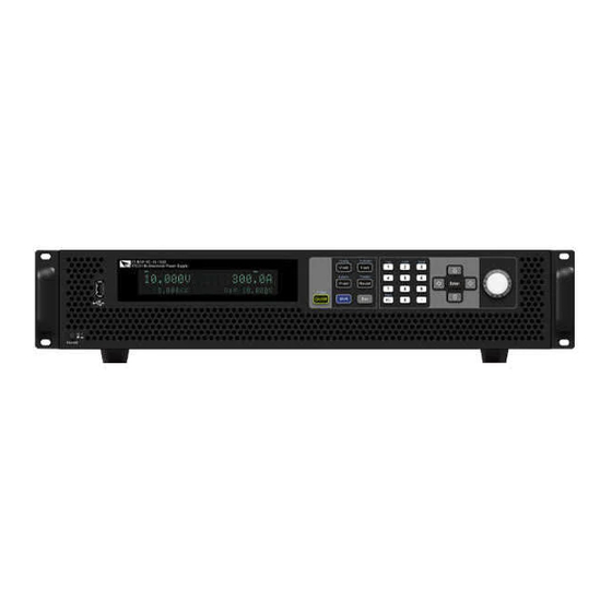
Page 15: Front-Panel Overview
1 Power On/Off switch 5 Numeric and composite keys 2 USB storage device connec- 6 Push-on knob tion port 7 Left, and right cursor navigation keys 3 Vacuum fluorescent display (VFD) 4 Function and composite keys Copyright © Itech Electronic Co., Ltd. -
Page 16: Keyboard Introduction
Enter key 3 Vacuum fluorescent display 7 Push-on knob (VFD) 4 Function and composite keys 1.3 Keyboard Introduction The keyboard introduction of this series instrument is shown as follows. 1U Model 2U Model Copyright © Itech Electronic Co., Ltd. - Page 17 Positive and negative signs Decimal point Left / Right The left and right navigation keys are used to adjust the cur- navigation sor to the specified position or scrolls pages to view menu keys items. Copyright © Itech Electronic Co., Ltd.
-
Page 18: Push-On Knob
Turn the keyboard lock on or off. [Shift]+[3] (Local) Switch remote control mode to local control mode. 1.4 Push-on Knob This series Bi-directional Programmable DC Power Supply provides a knob on the front panel as shown in the next figure. Copyright © Itech Electronic Co., Ltd. -
Page 19: Rear Panel Introduction
[Enter] key to confirm the operation. 1.5 Rear Panel Introduction The rear panel of the of the this series model (after removing the protective cov- er) is shown below. 1U Models 2U Models Copyright © Itech Electronic Co., Ltd. -
Page 20: Vfd Indicator Lamps Description
3 seconds. The keyboard lock Indicates that the instrument is turned on. is working in remote control mode. The power supply Error Error occur (Sink) is in constant resistance state. Copyright © Itech Electronic Co., Ltd. -
Page 21: Configuration Menu Function
Press [Esc] key to return to the previous menu level. The descriptions of configuration menu of the power supply are listed in the ta- ble below. Config Configuration menu of the power supply CC/CV priority mode setting Mode Constant voltage loop priority mode Copyright © Itech Electronic Co., Ltd. - Page 22 Once the voltage upper limit is Voltage Max modified here, the parameters related to the voltage setting will be limited by the upper limit here. Copyright © Itech Electronic Co., Ltd.
-
Page 23: System Menu Function
Set the sense function state. Turn the sense function off. Turn the sense function on. ListTrig Source Set the trigger method for the List files running. Immediate Trigger immediately Manual trigger Manual Bus trigger Copyright © Itech Electronic Co., Ltd. - Page 24 IP Mode: Auto IP: 0.0.0.0 Mask: 0.0.0.0 Gateway: 0.0.0.0 DNS1: 0.0.0.0 DNS2: 0.0.0.0 MAC: 8C:C8:F4:40:01:E1 MDNS Status: HostName: HostDesc: Domain: TCPIP:INSTR Socket Port: 30000 Configure LAN IP information. IP-Conf Configure LAN IP mode. IP-Mode Copyright © Itech Electronic Co., Ltd.
- Page 25 Configure the LAN services. Serv-Conf MDNS: MDNS service state. • • PING: PING service state. • • Telnet-scpi: telnet-scpi service state. • • Web: Web service state. • • VX-11: VX-11 service state. • • Copyright © Itech Electronic Co., Ltd.
- Page 26 Set Digital I/O By default, the menu item displays 7 options. You can set parameters Digital Port for each option respectively. After setting, the corresponding change to each option becomes valid immediately. When re-entering DigPort, Copyright © Itech Electronic Co., Ltd.
-
Page 27: Options Introduction
2.5.4 GPIB Interface (Optional). – IT-E177: Interface card that includes RS-232 communication interface, external analog and other functions. The accessory has a total of 10 pins, and the details of each pin are as follows: Copyright © Itech Electronic Co., Ltd. - Page 28 Fiber optic modules and cables are used for data transmission and commu- nication between parallel units, and are highly resistant to interference. The fiber optic module and cable are the necessary accessories for the parallel Copyright © Itech Electronic Co., Ltd.
- Page 29 • IT-E165B: Anti electromotive force module It is suitable for motor products, which can prevent the electromotive force generated during the operation of the motor from damaging the power sup- ply products. Copyright © Itech Electronic Co., Ltd.
-
Page 30: Inspection And Installation
Depending on the instru- ment model. For details, see 2.3 Con- necting the Power Cord. USB communication This accessory is se- cable lected when the USB in- terface is used for starting up remote operation. Copyright © Itech Electronic Co., Ltd. -
Page 31: Instrument Size Introduction
The instrument should be installed at well-ventilated and rational-sized space. Please select appropriate space for installation based on the instrument size. The detailed dimension drawings of this series instrument are as follows (unit: mm, deviation: ±1 mm): Copyright © Itech Electronic Co., Ltd. - Page 32 Inspection and Installation 1U Models Copyright © Itech Electronic Co., Ltd.
-
Page 33: Connecting The Power Cord
Inspection and Installation 2U Models 2.3 Connecting the Power Cord Precautions To prevent electric shock and damage to the instrument, observe the following precautions. Copyright © Itech Electronic Co., Ltd. - Page 34 Categories of Power Cords The standard power cord specifications for this series instruments are divided into the following types according to different regions: Copyright © Itech Electronic Co., Ltd.
- Page 35 High Input 3-Phase 3-Phase Rated Output Range Range Range Power -145 180-200 200-264 180-264 342-520 1.7kW 1.7kW 1.7kW 1.7kW 1.7kW 3.4kW 2.3kW 3.4kW 3.4kW 5.1kW 2.3kW 3.5kW 5.1kW 10.2kW 4.6kW 7.1kW 10.2kW 2.3kW 3.5kW Copyright © Itech Electronic Co., Ltd.
- Page 36 When the instrument is connected to the three phases of the three-phase power supply terminal, there is no need to pay attention to the current shar- ing problem, just connect it directly. The wiring diagram is as follows: Copyright © Itech Electronic Co., Ltd.
- Page 37 2. Confirm that the power switch is in the OFF position and verify that there is no dangerous voltage on the connection terminals. 3. Remove the protective cover outside the AC input terminal on the rear panel. Copyright © Itech Electronic Co., Ltd.
-
Page 38: Connecting The Device Under Test (Dut)
2.4 Connecting the Device Under Test (DUT) This section describes how to connect the test cables between the instrument and DUT. Precautions To prevent electric shock and damage to the instrument, observe the following precautions. Copyright © Itech Electronic Co., Ltd. - Page 39 Provision must be made to disconnect the external energy source before touching the output or sense terminals. • Always use test cables provided by ITECH to connect the equip- ment. If test cables from other factories are used, please confirm the maximum current that the test cables can withstand.
- Page 40 The connection diagram and steps of remote measurement are as follows: Copyright © Itech Electronic Co., Ltd.
- Page 41 Lethal voltages may remain at the output terminals after turn-off. Verify that there is no dan- gerous voltage on the output or sense terminals before touching them. Copyright © Itech Electronic Co., Ltd.
-
Page 42: Remote Interface Connection
• VCP: Virtual serial port. For Win7 system, you can download IT-M3900 VCP driver from ITECH official website or contact technical support engineer; for Win10 system, you do not need to install VCP driver. The operation steps to change the USB interface type in System Menu are as follows. -
Page 43: Lan Interface
3. Press the Left/Right key to select LAN and press [Enter]. 4. Press the Left/Right key to select Info and press [Enter]. 5. Rotate the knob to view the LAN parameters. See the information in 1.8 Sys- tem Menu Function for details. Copyright © Itech Electronic Co., Ltd. - Page 44 Socket Port: This value indicates the port number corresponding to the service. Serv-Conf Configurable services include: MDNS, PING, Telnet-scpi, Web, VXI-11, and Raw Socket. How to Configure • IP-Conf Take manual configuration as an example. The steps are as follows: Copyright © Itech Electronic Co., Ltd.
- Page 45 PC over LAN interface and enter the instrument's IP address into the address bar at the top of your PC's Web browser, you can access the front pan- el control functions including the LAN configuration parameters. Copyright © Itech Electronic Co., Ltd.
- Page 46 This page allows you to monitor and control the instrument; • LAN Configuration: Reconfigure the LAN parameters; • Manual: Go to the ITECH official website and view or download the relevant documents. • Upload: Performs a system upgrade. Copyright © Itech Electronic Co., Ltd.
-
Page 47: Can Interface
The instruments allow any combination of up to six simultaneous socket and telnet connections to be made. ITECH instruments have SCPI socket services, which can be used to send and receive SCPI commands, queries, and query responses. All commands must be terminated with a newline for the message to be parsed. - Page 48 Ensure you have used the correct communication cable (CAN_H, CAN_L). Please pay attention that some cable may not have a correct internal wiring even it is with an appropriate plug. • The interface cable is correctly connected (CAN_H to CAN_H, CAN_L to CAN_L). Copyright © Itech Electronic Co., Ltd.
-
Page 49: Gpib Interface (Optional)
1. Ensure that the instrument's power switch is off, that is, the instrument is in Power Off state. 2. Insert the separately purchased GPIB interface card into the card slot on the rear panel of the instrument. Copyright © Itech Electronic Co., Ltd. -
Page 50: Interface (Optional)
When using the RS-232 interface for communication, connect the pin 1, pin 2, and pin 3 of the IT-E177 to the PC. The pin description is as follows: Pins Description TXD, transmit data RXD, receive data DGND, ground Copyright © Itech Electronic Co., Ltd. - Page 51 Make sure the correct cable and adapter are connected. Note that internal wiring may not be correct even if the cable has a suitable plug; • The cable must be connected to the correct serial ports (COM1, COM2, etc) of PC. Copyright © Itech Electronic Co., Ltd.
-
Page 52: Getting Started
When you turn the POWER switch on for the first time after purchase, the instru- ment starts with its factory default settings. Each time thereafter, the instrument starts according to the setting that you selected as outlined in 5.6 Set the Power-on State (PowerOn). Copyright © Itech Electronic Co., Ltd. - Page 53 AC input power to the unit. Power Switch Introduction The power switch is located in the lower left corner of the front panel. The power switch is a button, and pressing once indicates ON and pressing again indicates OFF. Copyright © Itech Electronic Co., Ltd.
- Page 54 Error message Error Description Eeprom Failure The EEPROM is damaged. Main FrameInitializeLost The system setting data is lost. Calibration Data Lost The factory calibration data in EE- PROM is lost. Copyright © Itech Electronic Co., Ltd.
- Page 55 There can only be one single unit as the Master, and the other single units must be set to Slave. After the setting is completed, power off and restart each single unit. 5. If the instrument still does not start, contact ITECH technical support engineer. Copyright © Itech Electronic Co., Ltd.
-
Page 56: Set Output Value
• The user can set the parameters related to instrument protection function in the Protect menu, including OCP /OVP/OPP /UCP/UVP. • Function menu includes output list, batterycharging test function and so on. Copyright © Itech Electronic Co., Ltd. -
Page 57: On/Off Control
DUT. If the power supply has no output after the output is turned on, check the voltage and current setting value, set the voltage and current to a non-zero value, and then turn on the output. Copyright © Itech Electronic Co., Ltd. -
Page 58: Power Supply Function
When [I-set] key is pressed, the key light is lit and the output current value can be set. Press numeric keys or rotate the knob to adjust the value in the current setting area indicated by the cursor. This value takes effect when you press [Enter]. Copyright © Itech Electronic Co., Ltd. -
Page 59: Set The Output Power
Do not use CV priority mode with low-impedance sources such as batteries, power supplies, or large charged capacitors. Copyright © Itech Electronic Co., Ltd. - Page 60 When the output voltage exceeds the over-voltage protection setting, the output will shut down. Copyright © Itech Electronic Co., Ltd.
- Page 61 A CC (constant current) status flag indicates that the output current is being regulated and the output voltage is within its limit settings. Copyright © Itech Electronic Co., Ltd.
- Page 62 Press the [I-set] key on the front panel to set the output current value b. Press the [V-set] key on the front panel to set the voltage upper limit Vh, and press [V-set] again to set the voltage lower limit Vl. Copyright © Itech Electronic Co., Ltd.
-
Page 63: Set The Internal Resistance
Set the DUT (power supply) to output 80V, 10A. At this time, 10Ω in sink mode (according to the formula I=U/R, sink current is 80÷10=8A), due to the limitation of Is=–5A in CC priority mode, the actual Copyright © Itech Electronic Co., Ltd. -
Page 64: Set The Output-On/Output-Off Delay
Protection function menu for the power supply Protect Overvoltage protection Turn the OVP function off. (Def) Turn the OVP function on. Level OVP limit Protection delay time, Delay Protection Delay. Overcurrent protection Turn the OCP function off. (Def) Copyright © Itech Electronic Co., Ltd. - Page 65 Protection delay time, Delay Protection Delay. Undervoltage protection Turn the UVP function off. (Def) Turn the UVP function on. Indicates the instrument warm-up time. This time Warm-up is set to prevent the in- strument from triggering Copyright © Itech Electronic Co., Ltd.
- Page 66 The first row shows the meter voltage and the meter current value. • The left side of the second row shows the specific protection information (such as overvoltage protection OVP), the right side shows the duration of Copyright © Itech Electronic Co., Ltd.
-
Page 67: Set Over-Voltage Protection (Ovp)
The external (AC input) inputs a higher voltage. • The power supply outputs a high voltage due to a fault. Please avoid inputting a external voltage higher than 120% rated value, or the instrument will be damaged. Copyright © Itech Electronic Co., Ltd. -
Page 68: Set Over-Current Protection (Ocp)
(1U Model) 2. Press the composite keys [Shift]+[Recall] (Protect) on the front panel to en- ter the protection menu. (2U Model) 3. Rotate the knob to select 2. OCP (Off) and press [Enter]. Copyright © Itech Electronic Co., Ltd. -
Page 69: Set Over-Power Protection (Opp)
4. Press the left/right key or rotate the knob to select On and press [Enter] to enter the setting interface. 5. Set the protection limit Level and the delay time Delay in sequence, and press [Enter] to confirm. Copyright © Itech Electronic Co., Ltd. -
Page 70: Set Under-Current Protection (Ucp)
4. Press the left/right key or rotate the knob to select On and press [Enter] to enter the setting interface. 5. Set the warm-up time Warm-up, protection limit Level and delay time Delay in sequence, and then press [Enter] to confirm. Copyright © Itech Electronic Co., Ltd. -
Page 71: Set Under-Voltage Protection (Uvp)
[Enter] to confirm. The VFD screen returns to the Protect menu and the UVP setting (take 10S, 1V, 1S as an example) is displayed as follows: PROTECT 5.UVP 10S, 1V, 1.000S Copyright © Itech Electronic Co., Ltd. -
Page 72: Over-Temperature Protection (Otp)
When you return power to the instrument, verify that the cooling fan is running. If not, please contact ITECH Technical Support. Leaving the instrument powered on with an inoperative cooling fan may result in damage to the instrument. -
Page 73: Function Menu For Power Supply
This series power supply supports a total of 10 List files (List01 to List10), each of which can be set up to 200 steps. You need to edit the voltage/current value, slope and time width of each step, or you can set repeat times (1 to 65535) for Copyright © Itech Electronic Co., Ltd. - Page 74 Step 1 Slope value setting for Step1. Slope Step 1 Dwell time setting for Step1. The range is from Width 0.001 to 21000 in seconds. Repeat Set the number of list file repetitions. Copyright © Itech Electronic Co., Ltd.
- Page 75 1. Press the composite keys [Shift]+[I-set] (Function) on the front panel to en- ter the function menu. 2. Select 1. LIST: Off and press [Enter]. 3. Rotate the knob to select Edit and press [Enter] to enter the editing interface. Copyright © Itech Electronic Co., Ltd.
- Page 76 XXX.csv Not-Load Load YY/ZZ XXX indicates the name of the List file; YY indicates the serial number of the current List file; ZZ indicates the total number of the List file. Copyright © Itech Electronic Co., Ltd.
- Page 77 4. Press the Left/Right key to select Open and press [Enter]. 5. Press the Left/Right key to select Internal and press [Enter]. 6. Set the name of the List file to be recalled (that is, the file name set in Edit), and press [Enter]. Copyright © Itech Electronic Co., Ltd.
- Page 78 8. Based on the selected trigger method, perform the trigger operation. Take the manual trigger as an example. Press [Shift]+[On/Off](Trigger) on the front panel to run the selected List file. For details about the List trigger method, see 5.8 Select Trigger Source (Trig Source). Copyright © Itech Electronic Co., Ltd.
- Page 79 Import via U disk The instrument supports importing the edited .csv format file (the template can be downloaded from ITECH official website or contact ITECH to obtain) through the USB interface on the front panel, and generating voltage or cur- rent values after parsing, and then outputting complex voltage or current waveforms according to the time width specified by the user.
-
Page 80: Battery Charging/Discharging Test Function
4.6.2 Battery Charging/Discharging Test Function This series power supply provides the battery charging/discharging test function based on its unique bidirectional power supply properties. Suitable for charging/ discharging tests on all types of portable batteries. Copyright © Itech Electronic Co., Ltd. - Page 81 Set the voltage Charge / value for charging Discharge or discharging ac- cording to the se- lected test mode. Set the current val- Charge / ue for charging or Discharge I discharging Copyright © Itech Electronic Co., Ltd.
- Page 82 (Charge I) or discharging current (Discharge I) and the other parameters, and then press [Enter] to confirm. After the parameter setting is completed, the interface returns to the Battery function main interface and displays as follows: FUNCTION BATTERY Run Edit Copyright © Itech Electronic Co., Ltd.
-
Page 83: Built-In Waveform Function
The protocols/standards involved in the built-in waveforms include the following: • DIN40839 • ISO16750-2 • ISO21848 • SAEJ1113–11 • LV123 • LV124 This series 10V model do not support built-in waveform function. Copyright © Itech Electronic Co., Ltd. - Page 84 Run the Vehicle Waveform After turning on [On/Off], the output of the vehicle waveform is triggered accord- ing to the selected trigger method. Copyright © Itech Electronic Co., Ltd.
- Page 85 In this way, the user can create waveform between 8V to 32V. Evaluation of automotive starting DIN40839 waveform Select the automotive starting waveform with a starting voltage of 12V. Select the automotive starting waveform with a starting voltage of 24V. Copyright © Itech Electronic Co., Ltd.
- Page 86 User-defined the automotive starting waveform. User-de- fined volt- V=8.00V age value DIN40839 for 12V System Steps Voltage (V) Current(A) Width(mS) Slope(mS) 2000 DIN40839 for 24V System Steps Voltage (V) Current(A) Width(mS) Slope(mS) 2000 Copyright © Itech Electronic Co., Ltd.
- Page 87 12V; when the waveform program is divided into 16V-32V, the wave- form is consistent with the standard 24V waveform. The waveform diagram is shown below. How to Use Recall the self-defined DIN waveform operation (taking 12.5V voltage waveform as an example): Copyright © Itech Electronic Co., Ltd.
- Page 88 This test is applicable to equipment with re- Reset-Test set function. The minimum supply voltage Us- min (Usmin≤80V) Usmin This test verifies the behavior of a DUT dur- Starting- ing and after cranking. Profile Select the 12V test system. Copyright © Itech Electronic Co., Ltd.
- Page 89 Load-Dump Load dump curve Select centralized load dump Test A unsuppression Select the 12V voltage system Pulse width Peak voltage Select the 24V voltage system Pulse width Peak voltage Test B Select centralized load dump suppression Copyright © Itech Electronic Co., Ltd.
- Page 90 This test simulates the effect when a conventional fuse element melts in another circuit. • 12V system • 24V system How to recall this waveform from menu (take 12V system as an example): Copyright © Itech Electronic Co., Ltd.
- Page 91 2. Use the knob to select 3.Road-Vehicles = Off and press [Enter]. 3. Press the Left/Right key to select ISO16750-2 and press [Enter] to confirm. 4. Press the Left/Right key to select Reset-Test, and press [Enter] to confirm. Copyright © Itech Electronic Co., Ltd.
- Page 92 Curve should be selected based on actual test requirements. To create waveform within 12V, follow the set standards as below: I, II, III, and IV defined in the above standard correspond to levels 1, 2, 3, and 4 in the setup menu. Copyright © Itech Electronic Co., Ltd.
- Page 93 • The pulse duration of load dump is mainly determined by the time constant and pulse amplitude of the excitation circuit. Copyright © Itech Electronic Co., Ltd.
- Page 94 ≤350 (ms) – – If not otherwise agreed, use the upper voltage level with the upper value for internal resistance or use the lower voltage level with the lower value for in- ternal resistance. Copyright © Itech Electronic Co., Ltd.
- Page 95 ≤350 (ms) – – If not otherwise agreed, use the upper voltage level with the upper value for in- ternal resistance or use the lower voltage level with the lower value for internal resistance. Copyright © Itech Electronic Co., Ltd.
- Page 96 8. Press [On/Off] on the front panel to turn on the output. 9. According to the selected trigger method (same as the trigger method of the LIST function), for example, press [Shift]+[On/Off](Trigger) to trigger the output of the waveform. Copyright © Itech Electronic Co., Ltd.
- Page 97 LIST function), for example, press [Shift]+[On/Off](Trigger) to trigger the output of the waveform. Test Pulse max,dyn Detect the function when the DUT is under maximum dynamic Voltage U max,dyn and simulate the maximum dynamic Voltage of high-energy pulse raised from Copyright © Itech Electronic Co., Ltd.
- Page 98 DUT, the rise and fall time be- tween U and 16V level shall not be longer than 100ms. • t: Time (in ms) • U: Voltage (in V) Copyright © Itech Electronic Co., Ltd.
- Page 99 After turning on [On/Off] and triggering the waveform output, the instrument will apply the startup characteristic parameters as shown in the figure and table be- low to related input terminals of the DUT simultaneously. • t: Time time (in ms) t1: 5ms Copyright © Itech Electronic Co., Ltd.
- Page 100 Test–4 Starter motor engagement disturbance pulse Select the 12V voltage system For details, see Table 4–1 Parameter Description Select the 24V voltage system For details, see Table 4–1 Parameter Description Test–5 Load dump waveform Copyright © Itech Electronic Co., Ltd.
- Page 101 Test B Select centralized load dump suppression Select the 12V volt- age system Test pulse width Peak voltage Clamping voltage Select the 24V volt- age system Test pulse width Peak voltage Clamping voltage Copyright © Itech Electronic Co., Ltd.
- Page 102 Power Supply Function Test–2B Transient from DC motors acting as generators after ignition switch OFF: Parameters ≤0.05Ω ≤0.05Ω 0.2–2s 0.2–2s 1ms±50% 1ms±50% 1ms±50% 1ms±50% 1ms±50% 1ms±50% Test–4 Starter motor engagement disturbance pulse. Copyright © Itech Electronic Co., Ltd.
- Page 103 The relevant pa- rameters are introduced as follows: Please pay attention to whether the voltage value defined in the LV123 standard matches the rated voltage of the instrument, otherwise some waveforms cannot be recalled. Copyright © Itech Electronic Co., Ltd.
- Page 104 Range of lower limited operating ca- limited pability, includes the following options: • HV_1 • HV_2a • HV_2b • HV_3 highly- Range of highly limited operating ca- limited pability, includes the following options: • HV_1 • HV_2a • HV_2b Copyright © Itech Electronic Co., Ltd.
- Page 105 V4: Voltage in interval 4 upper- Range of upper limited operating ca- limited pability, with the following settings: • V1: Voltage in interval 1 • V2: Voltage in interval 2 • V3: Voltage in interval 3 Copyright © Itech Electronic Co., Ltd.
- Page 106 Set the number of test repetitions, ranging from 1 to 65535. The actual number of test executions = count * Save To Set the save address of the waveform File file, range: 1~10. Copyright © Itech Electronic Co., Ltd.
- Page 107 520V 140V 255V 350V 635V 300S 300S 300S 300S 300S 300S 300S 300S 10mS 12mS 300S 300S 300S 300S Actual num- Count*3 Count*3 Count*3 Count*3 ber of tests Upper-limited The waveform is as follows: Copyright © Itech Electronic Co., Ltd.
- Page 108 190V 340V 450V 750V 200V 360V 470V 770V 190V 340V 450V 750V 195V 350V 460V 760V 140V 255V 350V 635V Actual Count*3 Count*3 Count*3 Count*3 number of tests Lower-limited The waveform is as follows: Copyright © Itech Electronic Co., Ltd.
- Page 109 140V 255V 350V 635V 170V 250V 520V 160V 200V 450V 170V 250V 520V 165V 225V 485V 140V 255V 350V 635V Actual Count*3 Count*3 Count*3 Count*3 number of tests Highly-limited The waveform is as follows: Copyright © Itech Electronic Co., Ltd.
- Page 110 255V 350V 10mS Actual number Count*3 Count*3 Count*3 of tests How to Use The following is an example of how to use this function by recalling the LV123 standard regulation Unlimited and HV_1 waveform. Copyright © Itech Electronic Co., Ltd.
- Page 111 LV124 waveform protocol E-02 Transient overvoltage test waveform E-04 Jump start test waveform E-05 Load dump test waveform E-07 Slow decrease and increase of the supply voltage test waveform Ubmax Start voltage Ubmin Holding voltage Copyright © Itech Electronic Co., Ltd.
- Page 112 These overvoltages are simulated by means of this test. This test may be used for the electrical life test. The test pulse of E-02 Transient overvoltage is shown in the figure below: Copyright © Itech Electronic Co., Ltd.
- Page 113 Dumping of an electric load, in combination with a battery with reduced buffering ability, results in an energy-rich overvoltage pulse due to the generator charac- teristics. The test pulse of E-05 Load Dump is shown in the figure below: Copyright © Itech Electronic Co., Ltd.
- Page 114 The reset behavior is represented by a voltage variance and a time variance. Two different test sequences are required to simulate different switchoff times. A component must always undergo both sequences. Copyright © Itech Electronic Co., Ltd.
- Page 115 In order to cover both cases, two different test sequences are required. A component must al- ways undergo both sequences. • Cold Start Test Pulse • Warm Start Test Pulse Copyright © Itech Electronic Co., Ltd.
- Page 116 The related parameters of the built-in waveform of the instrument are introduced as follows: LV148 LV148 E-01 Long-term overvoltages The component's resistance to long-term overvoltage is tested. A generator control fault during driving operation is simulated. E-02 Transient overvoltages Copyright © Itech Electronic Co., Ltd.
- Page 117 0V and the sudden reconnect the system volt- age by a charged or new energy storage battery. T1 Holding Holding time Time T1 Rising Rising time Time E-08 Reset behavior Copyright © Itech Electronic Co., Ltd.
- Page 118 E-18 Overvoltage range The test is to show the load cut-off during storage charging and check the changes of the operating behavior into the overvoltage range. E-01 The waveform is as follows: Copyright © Itech Electronic Co., Ltd.
- Page 119 Power Supply Function E-02 The waveform is as follows: Copyright © Itech Electronic Co., Ltd.
- Page 120 Power Supply Function E-03 The waveform is as follows: E-04 The waveform is as follows: Copyright © Itech Electronic Co., Ltd.
- Page 121 Power Supply Function E-06A The waveform is as follows: Copyright © Itech Electronic Co., Ltd.
- Page 122 Power Supply Function E-06B The waveform is as follows: E-07 The waveform is as follows: Copyright © Itech Electronic Co., Ltd.
- Page 123 Power Supply Function T1 and tr1 need to be manually set by the user. E-08 The waveform is as follows: Copyright © Itech Electronic Co., Ltd.
- Page 124 Power Supply Function E-10 The waveform is as follows: E-15 The waveform is as follows: Copyright © Itech Electronic Co., Ltd.
- Page 125 Power Supply Function E-16 The waveform is as follows: Copyright © Itech Electronic Co., Ltd.
- Page 126 Power Supply Function E-18 The waveform is as follows: Copyright © Itech Electronic Co., Ltd.
- Page 127 1. Press the composite keys [Shift]+[I-set] (Function) on the front panel to en- ter the function menu. 2. Use the knob to select 3.Road-Vehicles = Off and press [Enter]. Copyright © Itech Electronic Co., Ltd.
-
Page 128: Solar Photovoltaic Curve Simulation Function (Sas)
Edit Edit a fixed format PV curve. Set the maximum power. Set the maximum power voltage. Formula Regulatory settings. The choice of solar panel materi- als under different regulations is different. Copyright © Itech Electronic Co., Ltd. - Page 129 You can edit the static PV curve and save it inside the instrument (up to 100 curve records can be saved), or you can customize the editing of the PV curve (up to 1 can be saved). Copyright © Itech Electronic Co., Ltd.
- Page 130 You can select the Curve file saved in the instrument to be in the Open state for later running. 1. Press the composite keys [Shift]+[I-set] (Function) on the front panel to en- ter the function menu. 2. Use knob to select 4. SAS: Off and press [Enter]. Copyright © Itech Electronic Co., Ltd.
- Page 131 At this point, the instrument enters the SAS mode, and the VFD screen is displayed as the main interface of the system, waiting to trigger the User-defined curve to run. 4. Turn on the [On/Off]. Copyright © Itech Electronic Co., Ltd.
-
Page 132: Battery Simulation Function
Run the currently selected user-de- fined battery simulation file. • Set the initial state of charge (SOC) of the battery. 0~100% cor- responds to the volt- Initial Value age range from no- load voltage to full- load voltage. Copyright © Itech Electronic Co., Ltd. - Page 133 Serial teries in series. Positive current limit val- ue, which simulates the maximum discharge cur- rent of the battery pack. Negative current limit value, which simulates the maximum charge current of the battery pack. Copyright © Itech Electronic Co., Ltd.
- Page 134 • Edit battery simulation curve file 1. You can contact ITECH Technical Support to obtain a template for the battery simulation curve file (.csv format). 2. Use the Excel tool to open the template file, edit the relevant parameters, and save.
- Page 135 3. Press the composite keys [Shift]+[I-set] (Function) on the front panel to enter the function menu. 4. Use knob to select 5.Battery Emulator: Off and press [Enter]. The interface is displayed as follows: FUNCTION BEMULATOR Copyright © Itech Electronic Co., Ltd.
- Page 136 If you want to stop running during the battery simulation test, you can do the fol- lowing: Press the composite keys [Shift]+[I-set] (Function) on the front panel to enter the function menu. Copyright © Itech Electronic Co., Ltd.
- Page 137 Function menu item will be displayed, you can re-enter the Function menu for editing; if Reset is selected, it means to stop the present run- ning and return to the main interface to wait for the next trigger operation. Copyright © Itech Electronic Co., Ltd.
-
Page 138: Basic Operation
This function can prevent the power supply from the panel keys misoperation during usage. Press the composite keys [Shift]+[2] (Lock) to lock front panel keys and the lock symbol “*” is shown on the front panel display. All panel keys, Copyright © Itech Electronic Co., Ltd. -
Page 139: Save And Recall Operations
Internal resistance of the power supply: Output Res Protect menu OCP/OVP/OPP/UCP/UVP switch status: On/Off OCP/OVP/OPP/UCP/UVP limit setting: Level OCP/OVP/OPP/UCP/UVP delay time: Delay UCP/UVP warm-up time: Warm-up 5.3.1 Save Operation The save operation procedures are as follows: Copyright © Itech Electronic Co., Ltd. -
Page 140: Recall Operation
Records current and voltage data during the data acquisition period. Configure the Function Menu 1. Press the composite button [Shift]+[1] (Log) on the front panel to enter the configuration menu of the data logging function. Copyright © Itech Electronic Co., Ltd. - Page 141 2. Set the value of Sample Period and press [Enter]. 3. Set the value of Duration and press [Enter]. 4. Set the value of Source and press [Enter]. 5. Set the value of Data Type and press [Enter]. Copyright © Itech Electronic Co., Ltd.
- Page 142 When the DC terminals detect that the voltage reaches the trigger voltage setting value and is within the range of the upper and lower trigger limits, a data recording operation is triggered. – Level: Trigger threshold. – Up-Level: Trigger upper limit value. Copyright © Itech Electronic Co., Ltd.
-
Page 143: Set The Beeper Status (Beep)
The first displayed menu item Beep is used to set the beeper status. 2. Press [Enter] key to enter the parameter setting interface. 3. Press the Left / Right key or turn the knob to adjust the value of this parameter. Copyright © Itech Electronic Co., Ltd. -
Page 144: Set The Power-On State (Poweron)
Voltage setting: Vs 0.002V interface Current setting: Is One percent of the rated current of the instrument Upper limit of voltage: Vh, and Upper limit value: lower limit of voltage: Vl 0.002V Lower limit value: 0 Copyright © Itech Electronic Co., Ltd. -
Page 145: Sense Function (Sense)
This series power supply supports two connection methods: Local measure- ment and Remote sensing. The remote sensing is used for maximizing meas- urement accuracy. (Refer to 2.4 Connecting the Device Under Test (DUT)) The procedures to set the menu item are as follows. Copyright © Itech Electronic Co., Ltd. -
Page 146: Select Trigger Source (Trig Source)
– Level: Trigger threshold. – Up-Level: Trigger upper limit value. – Down-Level: Trigger lower limit value. • External: Indicates the trigger occurs via the pin 4 of the digital I/O interface (P-IO). Copyright © Itech Electronic Co., Ltd. -
Page 147: Set The Communication Information (I/O Con)
2. Turn the knob to select the I/O and press [Enter]. 3. Press the Left / Right key or turn the knob to adjust the value of this parameter. 4. After the parameter settings are complete, press [Enter]. Copyright © Itech Electronic Co., Ltd. -
Page 148: Set Parallel Operation Mode (Parallel)
Total pa- rameter. For example, setting Total = 3 means that the total number of units in the parallel relationship is 3. Copyright © Itech Electronic Co., Ltd. - Page 149 (1 Master and 2 Slave) in parallel as an example. 1. Ensure that the power switches of the three units and the main switch of the AC power distribution box are off. 2. Refer Figure 5–1 Wiring connection diagram to connect three units. Copyright © Itech Electronic Co., Ltd.
- Page 150 2. Power off the three instruments and turn off the main switch of the AC distri- bution box. 3. Remove the cables connection of the System Bus and DC output terminals between three units. Copyright © Itech Electronic Co., Ltd.
-
Page 151: Digital I/O Function (Digital Port)
Input/Output Sync-On, synchronous on Pulse signal control. Input/Output Sync-Off, synchronous off Pulse signal control. Ground terminal, that is, the negative terminal Level signal corresponding to each of the above 7 pins. Copyright © Itech Electronic Co., Ltd. - Page 152 (False) or low level (True) can be Output. – When pins 1 to 7 are configured to Input function, an external signal can be Input to this pin, and the instrument can detect the state of the exter- nal signal. Copyright © Itech Electronic Co., Ltd.
-
Page 153: Io-1. Ps-Clear, Not-Invert
IO-1 pin can be set to 【Ps-Clear】, 【Input】, 【Output】. Parameter Description IO–1. Ps-Clear, Parameter setting for pin 1. Not-Invert Not- Indicates whether to invert the input/output Invert pulse or level signal. • Invert: Yes Invert • Not-Invert: No Copyright © Itech Electronic Co., Ltd. - Page 154 Pulse input: When the instrument is under protection, the instrument will clear protection after receiving the pulse signal from external input. 1. Refer to the figure below to connect pin 1 to the external oscilloscope. Copyright © Itech Electronic Co., Ltd.
-
Page 155: Io-2. Ps, Not-Invert
IO-2 pin can be set to 【Ps】, 【Input】, 【Output】. Parameter Description IO–2. Ps, Not- Parameter setting for pin 2. Invert Not- Indicates whether to invert the input/output Invert pulse or level signal. • Invert: Yes Invert Copyright © Itech Electronic Co., Ltd. - Page 156 2 outputs high level; when the instrument is under protection, pin 2 outputs low level. When pin 2 is set to Invert, the output level is completely opposite. 1. Refer to the figure below to connect pin 2 to the external oscilloscope. Copyright © Itech Electronic Co., Ltd.
-
Page 157: Io-3. Off-Status, Not-Invert
This default function indicates the exist- Status ing [On/Off] state of the instrument. Input Pin 3 receives the level signal from the outside. Output Pin 3 sends the digital signal (1, 0, PWM) to the outside. Copyright © Itech Electronic Co., Ltd. - Page 158 1. Refer to the figure below to connect pin 3 to the external oscilloscope. 2. Confirm that pin 3 function is set to the default option, namely IO-3. Off-Status, Not-Invert. 3. Turn on [On/Off]. Copyright © Itech Electronic Co., Ltd.
-
Page 159: Io-4.Trig(In), Not-Invert
Meter Triggers the run- ning of Meter function. This function needs to be triggered at the upper com- puter side through SCPI in- struction. For de- tails, refer to instructions Copyright © Itech Electronic Co., Ltd. - Page 160 Taking the triggering of List function as an example, the text below will introduce how to use pin 4’s default function Ext-Trig. • Trig–Out 1. Refer to the figure below to connect pin 4 to the external oscilloscope. Copyright © Itech Electronic Co., Ltd.
- Page 161 5. Check the oscilloscope and confirm whether pin 4 has following pulse signal output. Level rise slope 10us Level fall slope Minimum time width 30us for low level keep • Trig-In 1. Refer to the figure below to connect pin 4 to the external oscilloscope. Copyright © Itech Electronic Co., Ltd.
-
Page 162: Io-5. Inh-Living, Not-Invert
IO-5 pin can be set to 【Inhibit】, 【Input】, 【Output】. Parameter Description IO–5. Living, Parameter setting for pin 5. Not-Invert Not- Indicates whether to invert the input/output pulse or Invert level signal. • Invert: Yes Invert Copyright © Itech Electronic Co., Ltd. - Page 163 The [On/Off] button light is lighted on and VFD still displays On, but the actual output is 0; when pin 5 receives high level sig- nal again, the output state is recovered. Copyright © Itech Electronic Co., Ltd.
- Page 164 The pa- rameter requirements of this pulse signal are as follows: Level rise slope 10us Level fall slope Minimum time width 30us for low level keep Copyright © Itech Electronic Co., Ltd.
-
Page 165: Io-6. Sync-On, Not-Invert
In addition, the VFD screen on the front panel displays Inhibit-Ps. When the protection state is cleared, manually turn on [On/Off] again. 5.11.6 IO–6. Sync-On, Not-Invert IO-6 pin can be set to 【Sync-On】, 【Input】, 【Output】. Copyright © Itech Electronic Co., Ltd. - Page 166 When pin 6 is set to default Sync-On function, pin 6 has bi-directional I/O func- tion, which can receive pulse signal input from the external instrument and also can output pulse signal to external instrument. The parameter requirements of this pulse signal are as follows: Copyright © Itech Electronic Co., Ltd.
- Page 167 4. Set the voltage to 10V on the front panel of instrument A, and turn on [On/Off]. At this time, check the oscilloscope. The instrument A’s pin 6 outputs pulse signal and the instrument B’s output function is synchronously turned on. Copyright © Itech Electronic Co., Ltd.
-
Page 168: Io-7. Sync-Off, Not-Invert
When pin 7 is set to default Sync-Off function, pin 7 has bi-directional I/O func- tion, which can receive pulse signal input from the external instrument and also can output pulse signal to external instrument. The parameter requirements of this pulse signal are as follows: Copyright © Itech Electronic Co., Ltd. - Page 169 4. Press [On/Off] on the front panel of instrument A to turn off the output function. At this time, check the oscilloscope. The instrument A’s pin 7 outputs pulse signal and the instrument B’s output function is synchronously turned off. Copyright © Itech Electronic Co., Ltd.
-
Page 170: Analogue Function (Ext-Program) (Optional)
The analog function interface is located on the optional IT-E177. The pins de- scription is as below. Pins Name Type Description 1, 2, 3 TXD, Commu- RS232 interface connection terminal. RXD, nication DGND terminal Ground Ground for analog inputs and outputs. Copyright © Itech Electronic Co., Ltd. - Page 171 The analog quantity menu items and parame- ters are described below: Ext-Program External analog function menu On / Off Function switch: • On: Turns on the external analog function. In this state, the channel parameters cannot be set. Copyright © Itech Electronic Co., Ltd.
- Page 172 Mx and Mb according to the following formulas, and then set the two values through the front panel keys or SCPI remote commands. The principle of parameter setting of Ch1 and Ch2 and Ch3 is the same, so the description will not be repeated. Copyright © Itech Electronic Co., Ltd.
- Page 173 CV priority • CC priority How to Use The following takes the CV priority mode as an example to introduce the usage steps. 1. Refer to the figure below to complete the pin connection. Copyright © Itech Electronic Co., Ltd.
- Page 174 Press the composite keys [Shift]+[P-set] (System) on the front panel to enter the system menu. b. Use knob key to select Ext-Program and press [Enter]. c. Set the Ext-Program→On / Off to On to turn on the analog function. Copyright © Itech Electronic Co., Ltd.
-
Page 175: View The System Information (System Info)
Display the version information of the control panel 2. Date Display the system time. Voltage Max Display the maximum voltage value. Voltage Min Display the minimum voltage value. Current Max Display the maximum current value. Copyright © Itech Electronic Co., Ltd. -
Page 176: Restored To Factory Setting (System Reset)
Voltage setting: Vs 0.002V interface Current setting: Is One percent of the rated current of the instrument Upper limit of voltage: Vh, and Upper limit value: lower limit of voltage: Vl 0.002V Lower limit value: 0 Copyright © Itech Electronic Co., Ltd. - Page 177 • DNS1/DNS2: 0.0.0.0 • Socket Port: 30000 LAN→Serv-Conf MDNS/PING/Telnet- scpi/Web/VX-11/ Raw-socket: On • VCP: 9600,8,N,1 • (Optional) RS232: 9600,8,N,1 • (Optional) External analog: Off • (Optional) GPIB: Ad- dress=1 • Digital Port IO–1: Ps-Clear Copyright © Itech Electronic Co., Ltd.
-
Page 178: System Upgrade
UCP/UVP Protection point: Level OVP/OCP/OPP/UCP/UVP Delay time: Delay UCP/UVP Warm time: Warm-up 5.15 System Upgrade This series power supply supports the upgrade of the system version. System upgrade includes the following two methods: Copyright © Itech Electronic Co., Ltd. - Page 179 For example, when there are multiple system upgrading package post- fixed with .itech in the root directory of your USB flash drive, you need to use a text editing tool to open the configuration file and specify the up- grade package name corresponding to the present upgrade operation.
- Page 180 2. Power on the instrument. At this point, press Shift for several times till the instrument can detect the system upgrading files in the USB flash drive. After the system upgrading files are detected, the interface displays as follows: Copyright © Itech Electronic Co., Ltd.
- Page 181 The system will automatically perform upgrading. If No is selected, it means to exit upgrading, and the system will di- rectly enter into the main interface. 5. After the upgrading is completed, you need to restart the instrument manually. Copyright © Itech Electronic Co., Ltd.
-
Page 182: Technical Specification
Besides, we will introduce the working environment and storage temperature. ♦ Main Specification ♦ IT-M3901C-10-170 ♦ IT-M3903C-10-340 ♦ IT-M3905C-10-510 ♦ IT-M3910C-10-1020 ♦ IT-M3906C-80-120 ♦ IT-M3912C-80-240 ♦ IT-M3906C-300-60 ♦ Supplemental Characteristics 6.1 Main Specification Copyright © Itech Electronic Co., Ltd. -
Page 183: M3901C-10-170
≤0.03% + 0.03%FS Read Back Current ≤0.1% + 0.1%FS Accuracy Power ≤0.5% + 0.5%FS Vp-p ≤65mVpp Voltage ripple Vrms ≤10mV Voltage ≤50ppm/℃ Setup Temperature Coefficient ≤50ppm/℃ Current Voltage ≤50ppm/℃ Read Back Temper- ature Coefficient ≤50ppm/℃ Current Copyright © Itech Electronic Co., Ltd. - Page 184 Voltage 0 to 10V corresponds to external monitor- voltage monitor ing voltage 0 to 10V Other parameters: 3 phase: 110V~520V Voltage AC Input Single phase: 85V~300V Frequency 50Hz/60Hz Max. apparent 1.85kVA power Max. input current 12.5Aac1 Max. efficiency Copyright © Itech Electronic Co., Ltd.
-
Page 185: M3903C-10-340
-240A~340A Power -2400W~3400W Rated value Resistance in series (CV 0~0.03Ω priority) Load resistance (CC 0.006Ω~2Ω priority) Voltage 0.001V Current 0.01A Power Setup Resolution Resistance in series (CV 0.001Ω priority) Load resistance (CC 0.001Ω priority) Copyright © Itech Electronic Co., Ltd. - Page 186 Voltage ≤10ms Time Voltage ≤0.05% + 0.05%FS Line Regulation Current ≤0.05% + 0.05%FS Voltage ≤0.002%*I + 0.05%FS Load Regulation Current ≤0.05% + 0.05%FS -245A or 345A Output protection 10.5V Overpower protection -2448W or 3468W Copyright © Itech Electronic Co., Ltd.
- Page 187 Standard Interface Command Response Time 0.1ms Parallel Number ≤16 Working Temperature 0~40℃ Storage Temperature -10℃~70℃ IP20 Isolation DC to GND 300Vdc Isolation AC to GND 3500Vdc Cooling Dimension ( mm) 660mm*437mm*43.5mm Weight( net) 12.5kg Copyright © Itech Electronic Co., Ltd.
-
Page 188: M3905C-10-510
≤0.03% + 0.03%FS Read Back Current ≤0.1% + 0.1%FS Accuracy Power ≤0.5% + 0.5%FS Vp-p ≤65mVpp Voltage ripple Vrms ≤10mV Voltage ≤50ppm/℃ Setup Temperature Coefficient ≤50ppm/℃ Current Voltage ≤50ppm/℃ Read Back Temper- ature Coefficient ≤50ppm/℃ Current Copyright © Itech Electronic Co., Ltd. - Page 189 Voltage 0 to 10V corresponds to external voltage monitor monitoring voltage 0 to 10V Other parameters: 3phase 110V~520V Voltage AC Input Single phase 85V~300V Frequency 50/60Hz Max. apparent 5.55kVA power Max. input current 12.5Aac Max. efficiency Copyright © Itech Electronic Co., Ltd.
-
Page 190: M3910C-10-1020
-720A~1020A Power -7200W~10200W Rated value Resistance in series 0~0.02Ω (CV priority) Load resistance 0.00015Ω~0.5Ω (CC priority) Voltage 0.001V Current 0.1A Power Setup Resolution Resistance in series 0.001Ω (CV priority) Load resistance 0.001Ω (CC priority) Copyright © Itech Electronic Co., Ltd. - Page 191 Voltage ≤10ms Time Voltage ≤0.05% + 0.05%FS Line Regulation Current ≤0.05% + 0.05%FS Voltage 0.0035%*I + 0.05%FS Load Regulation Current ≤0.05% + 0.05%FS -740A or 1040A 10.5V Output protection Overpower -7344W or 10710W protection Copyright © Itech Electronic Co., Ltd.
- Page 192 Current harmonics ≤3% Standard: USB/LAN/CAN/IO Standard Interface Optional: GPIB/Analog/RS232 Command Re- 0.1ms sponse Time Parallel Number ≤8 Working 0~40℃ Temperature Storage -10℃~70℃ Temperature IP20 Isolation DC to GND 300Vdc Isolation AC to GND 3500Vdc Copyright © Itech Electronic Co., Ltd.
-
Page 193: M3906C-80-120
Resistance in series ≤1%FS (CV priority) Load resistance Lower limit: 1/(1/Rset+(1/Rset)*0.05+0.0005) (CC priority) Upper limit: 1/(1/Rset-(1/Rset)*0.05-0.0005) Voltage ≤0.03% + 0.03%FS Read Back Current ≤0.1% + 0.1%FS Accuracy Power ≤0.5% + 0.5%FS Voltage ripple Vp-p ≤200mVpp Copyright © Itech Electronic Co., Ltd. - Page 194 External analog (optional) External programming voltage 0 to 80V Corre- voltage program sponding voltage 0 to 10V Voltage 0 to 80V corresponds to external monitor- voltage monitor ing voltage 0 to 10V Other parameters: Copyright © Itech Electronic Co., Ltd.
-
Page 195: M3912C-80-240
Isolation AC to GND 3500Vdc Cooling Dimension ( mm) 660mm*437mm*43.5mm Weight( net) 15kg 6.1.6 IT-M3912C-80-240 Parameter IT-M3912C-80-240 Voltage 0~80V Current -240A~240A Power -12000W~12000W Rated value Resistance in series 0~0.3Ω (CV priority) Load resistance 0.005Ω~400Ω (CC priority) Copyright © Itech Electronic Co., Ltd. - Page 196 ≤30ms Fall Time( no load ) Voltage ≤30ms Fall Time( full load ) Voltage ≤15ms Transient Response Time Voltage ≤1ms change from 20% to 90% of rated current Line Regulation Voltage ≤0.01% + 0.01%FS Copyright © Itech Electronic Co., Ltd.
- Page 197 13kVA power Max. input current 25Aac Max. efficiency Power Factor 0.99 DC component ≤0.2A Current harmonics ≤3% Standard: USB/LAN/CAN/IO Optional: GPIB/Analog/RS232 Standard Interface Command Re- 0.1ms sponse Time Parallel Number ≤16 Working 0~40℃ Temperature Copyright © Itech Electronic Co., Ltd.
-
Page 198: M3906C-300-60
0.001A Resolution Power Voltage ≤0.03% + 0.03%FS Current ≤0.1% + 0.1%FS Power ≤0.5% + 0.5%FS Setup Accuracy Resistance in ser- ≤1%FS ies (CV priority) Load resistance Lower limit: 1/(1/Rset+(1/Rset)*0.05+0.0001) (CC priority) Upper limit: 1/(1/Rset-(1/Rset)*0.05-0.0001) Copyright © Itech Electronic Co., Ltd. - Page 199 -10V to 10V External analog (optional) External programming voltage 0 to 300V Corre- voltage program sponding voltage 0 to 10V Voltage 0 to 300V corresponds to external moni- voltage monitor toring voltage 0 to 10V Copyright © Itech Electronic Co., Ltd.
- Page 200 Isolation DC to GND 600Vdc Isolation AC to GND 3500Vdc Cooling Dimension ( mm) 660mm*437mm*43.5mm Weight( net) 15kg * At low voltage input, the set power will decrease. For more information, please contact ITECH. Copyright © Itech Electronic Co., Ltd.
-
Page 201: Supplemental Characteristics
Technical Specification 6.8 Supplemental Characteristics State storage capacity: 10 sets Recommended calibration frequency: once a year Cooling style: fans Copyright © Itech Electronic Co., Ltd. -
Page 202: Routine Maintenance
During self-test, errors may be induced by signals present on ex- ternal wiring, such as long test leads that can act as antennae. 7.2 Cleaning and Maintenance To ensure the safety function and performance of the instrument, please clean and maintain the instrument properly. Copyright © Itech Electronic Co., Ltd. -
Page 203: Contact Of Itech Engineers
If there are still some problems, carefully read the Warranty and Limitation of Warranty in the preface of the manual. Confirm that your instrument complies with warranty service conditions. If after your warranty expires, ITECH offers re- pair services at competitive prices. -
Page 204: Return For Repair
4006-025-000 for technical support and services. 7.4 Return for Repair If your instrument fails during the warranty period, ITECH will repair or replace it under the terms of your warranty. After your warranty expires, ITECH offers re- pair services at competitive prices. Also you can purchase an extended mainte- nance service contract that exceeds the standard warranty period. - Page 205 ITECH recommends that you retain the original shipping carton for return ship- ments and always insure shipments. To ship the unit to ITECH for service or repair: 1. Download the ITECH maintenance service application from our website, complete it and place it in the box with the instrument.
-
Page 206: A Appendix
♦ Fuse Replacement A.1 Specifications of Red and Black Test Cables ITECH provides you with optional red and black test cables, which are sold indi- vidually and you can select for test. For specifications of ITECH test cables and maximum current values, refer to the table below. -
Page 207: Troubleshooting
Larger diameter wire sizes will help minimize wire voltage drops. Twisting or bundling wires will help reduce transient voltage drops. A.2 Troubleshooting The fault information of this series of instruments is described below. Copyright © Itech Electronic Co., Ltd. - Page 208 Master, and the oth- er units are Slave. FIBER EXT UNLOCK The outer ring of the fiber is Fiber multi-master not locked. parallel: set the par- allel in the System menu in turn. For details, see 5.10 Copyright © Itech Electronic Co., Ltd.
-
Page 209: Fuse Replacement
If there are no fuse assembly on the instrument rear panel, it means that you can’t replace the fuse by yourself. Please contact the ITECH engineer on the condition of the same malfunction. - Page 210 2. Have a visual inspection of the fuse to see whether it is burnt out; if yes, replace it with another fuse of the same specification. Re- fer to the corresponding technical specifi- cations for fuse rating. Copyright © Itech Electronic Co., Ltd.
- Page 211 3. Please replace with a fuse of the same specification. Refer to the technical specifi- cation of the corresponding instrument. 4. When install, put into the fuse box firstly. Then Push and turn the fuse box to 90 de- grees clockwise. Copyright © Itech Electronic Co., Ltd.
- Page 212 Facebook LinkedIn YouTube...
Need help?
Do you have a question about the IT-M3900C Series and is the answer not in the manual?
Questions and answers