Table of Contents
Advertisement
Quick Links
Advertisement
Table of Contents

Related Manuals for Bay-Tek Lil Ticket Monster


Summary of Contents for Bay-Tek Lil Ticket Monster
- Page 1 SERVICE MANUAL PLACE SERIAL NUMBER LABEL HERE...
-
Page 2: Factory Contact Information
FACTORY CONTACT INFORMATION BAY TEK ENTERTAINMENT Pulaski Industrial Park 1077 East Glenbrook Drive Pulaski, WI 54162 USA SIGN UP TO RECEIVE OUR E-MAILS! Stay up to date on the latest game information, new product launches, early notification of parts specials, updates of retro fit parts, software upgrades, best practices and more! Visit baytekent.com and enter your email to sign up! You can also register your new game at baytekent.com/register SALES... -
Page 3: Table Of Contents
TABLE OF CONTENTS FACTORY CONTACT INFORMATION ………...………….………….. 2 TABLE OF CONTENTS …………………..……………….…………….. 3 WELCOME TO LIL’ TICKET MONSTER ……….…….……………….. 4 GAME SPECIFICATIONS …………….……………………………….. 5 SAFETY PRECAUTIONS ……………………...……………………….. 6 REMOVABLE MARQUEE ……..………..………………..…………….. 6 GAME SET UP …………………………………………………..…. 7 - 12 CARD SWIPE INSTALLATION ……………………………………….. 13 AVAILABLE BLANKING PLATES …………………………………….. -
Page 4: Welcome To Lil Ticket Monster
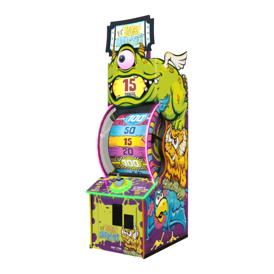
WELCOME TO LIL TICKET MONSTER Congratulations on your purchase! The beloved Lil’ Monsters : Burb, Grunt, and Toot are delighted to be a part your game room! The Lil’ Monsters are fun and friendly to all age groups, creating multi-generation appeal to anyone that steps through your doors! Please take a moment to read through this manual and be sure to contact our factory if you have any questions, or would like some more information. -
Page 5: Game Specifications
GAME SPECIFICATIONS WEIGHT POWER REQUIREMENTS GAME WEIGHT 386 lbs. 175 kg 100-120 220-240 SHIP WEIGHT 471 lbs. 214 kg INPUT VOLTAGE GAME DIMENSIONS INPUT FREQUENCY 60 Hz 50/60 Hz WIDTH 30.75” 79 cm MAX OPERATING CURRENT DEPTH 43" 110 cm HEIGHT 106.25"... -
Page 6: Safety Precautions
SAFETY PRECAUTIONS REMOVABLE MARQUEE 8’ 10 1/4” (106.25 Inches) The marquee artwork can be removed to accommodate a lower ceiling height. 7’ 7” (91 Inches) Remove the marquee artwork to lower game to 7’ 7” (91 Inches) -
Page 7: Game Set Up
LIL TICKET MONSTER GAME SETUP The game will arrive on one pallet. Please inspect the pallet for shipping damage and report immediately to the freight company if any damage is found. Remove the cardboard from the pallet. Carefully remove the plastic wrap securing the printed plexi wrapped to the side of the cabinet. - Page 8 LIL TICKET MONSTER GAME SETUP Hardware kits consist of: 32 of A5SCPH151 used to install the eyeball light and printed plexi wrap. 2 of A5SCPH230 and 2 of A5NULO030 used to secure plexi wrap below A5SCPH151 monitor. 1 of A5BOHH060 , 1 of A5WASI020, and 1 of A5WAFL060 are to be...
- Page 9 LIL TICKET MONSTER GAME SETUP Rotate upper marquee in place: Remove the lower bolt (A5BOPH320) from both left and right sides of marquee arm. Leave the top bolt in place. Rotate the marquee upward and re-insert the same bolts previously removed into the left hole.
- Page 10 LIL TICKET MONSTER GAME SETUP Pull the printed plexi wrap around the front of the game tightly, with the eyeball light through the round cutout in the plexi. Continue wrapping the top of the cabinet and get ready to insert one screw in this location.
- Page 11 LIL TICKET MONSTER GAME SETUP Continue installing the black screws from the hardware kit using a #2 square bit screwdriver in both the left side and right side printed plexi wrap. A5SCPH151 There are a total of 15 screws in each side.
- Page 12 LIL TICKET MONSTER GAME SETUP Install the 2 center bolts and nuts under the monitor. The printed plexi wrap is secured to small “L” brackets using a Phillips bolt and nut from the hardware kit. A5NULO030 A5SCPH230 Push the 2 bolts through the printed plexi, through the hole in the “L”...
-
Page 13: Card Swipe Installation
CARD SWIPE SYSTEM INSTALLATION The Lil Ticket Monster game is pre-wired with an UCL (Universal Card Link) connector to accept Card Swipe systems from many different manufacture’s. Please follow these instructions to make full use of this capability. AACE26013 Power In... -
Page 14: Game Play Theory Of Operation
GAME PLAY THEORY OF OPERATION The game is designed to give tickets after the player lifts, then pushes down on the plunger handle. Upon coin up, the solenoid on the left side of the wheel will engage and provide a mechanical link from the plunger handle to the wheel. -
Page 15: Main Menu Functions
MAIN MENU FUCTIONS The Menu and Menu Select buttons are located inside the front door. Hold the MENU button down for 1 second to open the main menu on the monitor. Press MENU to scroll through the options, and MENU SELECT to change the settings. MAIN MENU Clear Credits Press the... -
Page 16: Audio Settings
ATTRACT AND VOLUME MENU Scroll through the options by pressing the “MENU” button. Change selection with the “SELECT” button. Scroll to “BACK” and press the “SELECT” button to go back to the main menu. Default settings are highlighted in yellow below. ATTRACT TIME DISABLED Sets the amount of minutes between the attract mode cycles. -
Page 17: Payout Settings Menu
PAYOUT SETTINGS MENU Scroll through the options by pressing the “MENU” button. Change selection with the “SELECT” button. Scroll to “BACK” and press the “SELECT” button to go back to the main menu. Default settings are highlighted in yellow below. CREDITS FREE …... -
Page 18: Ticket Patterns
TICKET PATTERNS There are 4 base ticket patterns to choose from. These base patterns can be adjusted by adding cover-up decals to the wheel over the minor and major bonus values. Base ticket values and minor and major bonus values can be changed in the “Payout Settings Menu” Tickets per game shown are average payout over time. - Page 19 TICKET PATTERNS There are 4 base ticket patterns to choose from. These base patterns can be adjusted by adding cover-up decals to the wheel over the minor and major bonus values. Base ticket values and minor and major bonus values can be changed in the “Payout Settings Menu” Tickets per game shown are average payout over time.
-
Page 20: Game Settings Menu
GAME SETTINGS MENU Scroll through the options by pressing the “MENU” button. Change selection with the “SELECT” button. Scroll to “BACK” and press the “SELECT” button to go back to the main menu. Default settings are highlighted in yellow below. ENTERTAINMENT ONLY “ON”... -
Page 21: Diagnostic Menu
DIAGNOSTIC MENU Ticket value on the wheel where arrow is pointing. Important: The wheel must be spun downward for this to be correct. Explained on the bottom of this page. Stop time: Amount of time the Graphic wheel coasts to a stop representation Revolutions of wheel speed... -
Page 22: How To Locate Circuit Boards
HOW TO LOCATE CIRCUIT BOARDS All circuit boards can be accessed from the back door of the game. A5PS1021 Power Supply AACB5156 AACB9600A Power Dist. Board Audio Board AACB8001-LTM AACB8001-LTM Light Board Light Board AACB26000 AAMB12-HD/LTM AACB26000 Wheel Control Motherboard Wheel Control AACB9605-CBL I/O Aux Board... -
Page 23: Circuit Board Layout
CIRCUIT BOARD LAYOUT Note: All boards are located in the back of the game. AACE26017 AACE26018 Power to Power to 8001 Board 9600 Board AACB9600A Audio Amplifier AACE26018 12 VDC In CE26014 CE26004 CE22504 CE26004 AACE26001 A5CE2300 Speakers Audio Cable AACB5156 CE26015 CE26013... -
Page 24: Wiring Diagrams
FRONT DOOR WIRING DIAGRAM Coin Switches and Lights To 12 Volt Bill Acceptor AACBL4A-DOORA Part # A5AC9101 4-5 VDC normally Red is 12 Volts DC on switches. White is Coin Up Signal Goes to 0 when Black is Ground activated. Normally 4-5 VDC between white and black wires AACE26013... - Page 25 WHEEL CONTROL BOARD WIRING DIAGRAM 13.5 Ohms 12 VDC when engaged AASO26001 Solenoid Assembly AACE26015 Normally Red and AACB4403 Power in from Orange LEDs are Home Reflector Sensor Power Dist Bd on solid AACE26000 AACB26000 Wheel Control A5CBL5900 Small USB AACE26007 communication Home Sensor...
- Page 26 LIGHTING WIRING DIAGRAM AACE22503 Marquee LED Color Lights AACE22502 Marquee White Lights Marquee Top of Game AACE22504 Marquee Power AACE26029 AACE26029 AACE26030 AACE26030 Left Window Right Window Left Window Right Window White Lights White Lights AACE22505 Colored LED’s Colored LED’s AACE22504 Marquee Power AACE26032...
- Page 27 SPEAKERS AND MOTHERBOARD COMMUNICATION Speaker AACE8811 3.3 Ohms AACE26001 A5MO2221 22” Monitor AACE26018 AACB9600A 12 VDC In From Audio Amplifier Power Distribution Board A5CORD20 VGA Cable to Monitor A5CE2300 Audio Filter Plug “input” cable into end of A5CORD21 AACB9605-CBL I/O Aux Board Red and yellow LEDs are normally flashing all the time.
- Page 28 AC IN & DC VOLTAGE WIRING DIAGRAM AACE26029 AACE26029 Left Window Right Window White Lights White Lights A5MO2221 22” Monitor AACE26018 AACB9600A Audio Amplifier AACE26004 AACE26004 Wheel Lights Wheel Lights A5CORD5 AACE26017 AACB8001-LTM Light Board A5PS1021 Power Supply CE22504 CE26014 CE26004 AACB5156 Power Dist.
-
Page 29: Troubleshooting Guide
TROUBLESHOOTING GUIDE Troubleshooting Strategy Use common sense and a systematic method of troubleshooting to determine the exact problem, probable cause and remedy. Use the process of elimination to find the faulty component. Always check for the simple and obvious causes first such as unplugged, loose or broken wires and bad sensors, bent, pinched, stuck or jammed components. - Page 30 TROUBLESHOOTING GUIDE Problem Probable Cause Remedy If all colored cabinet lights Check power to Light Board from Power Distribution are not functioning, check Board. Cable # CE26017. Check USB cable to Light Colored player Light Board Board from motherboard. Cable # A5CORD58 (AACB8001-LTM) console lighting not working...
- Page 31 TROUBLESHOOTING GUIDE Problem Probable Cause Remedy Opto Sensor on ticket Blow dust from sensor and clean with Tickets do dispenser dirty. isopropyl alcohol. not dispense Faulty ticket dispenser. Replace with working dispenser to isolate the or Wrong Tickets on problem. (A5TD1) amount monitor does dispensed.
- Page 32 TROUBLESHOOTING GUIDE Problem Probable Cause Remedy I/O Aux Board Issue Green power LED If it is off, then check 12 & 5 Volts DC coming into board on Game does not coin should be flashing. cable CE26014 from Power Distribution Board. up, and has no other If solid on, then it is not communicating with the motherboard.
- Page 33 TROUBLESHOOTING GUIDE Problem Probable Cause Remedy Inspect assembly for There are 2 identical sensor boards in the arrow housing. physical obstruction 2 sets of optos watch the notches on the edge of the wheel. These sensors keep track of how many notches pass by to Encoder Sensors determine wheel position.
-
Page 34: Bill Acceptor Diagnostics
TROUBLESHOOTING GUIDE Problem Probable Cause Remedy Check for I/O board USB Refer to “I/O Aux Board Issue” diagnostic cable communication. Section. Game not coining up Ensure game makes sound Check coin switches—both should be wired when coin switch is triggered. normally open. -
Page 35: Power Supply Diagnostics
POWER SUPPLY DIAGNOSTICS 1.) Verify AC power to game. Check power strip in front door. The rocker switch should be illuminated. 2.) Check connection to power supply. 3.) Ensure Power Supply switch is set to 115V (or 230V) (Some model power supplies may not have this) 4.) Ensure Power switch is on. -
Page 36: How To Change Software
HOW TO CHANGE SOFTWARE New Software Installation: The hard drive contains all the information about the game: Credits per play, ticket pattern, etc. Be sure to check this information after finishing installing new software. Turn off game by flipping the power switch on the power strip. Locate hard drive on motherboard. -
Page 37: How To Open The Front Plexi
HOW TO OPEN THE FRONT PLEXI The front plexi can be removed from the game to allow monthly cleaning. Instructions: Remove the back door of the game and set aside. Open the front door and locate the 2 latches securing the front plexi in place. -
Page 38: How To Adjust Arrow Sensor
HOW TO ADJUST ARROW SENSOR The wheel sensor “sees” the notches on the right side of the wheel. As the game is played, the wheel spins downward and the ticket value changes as the point of the arrow crosses the dividing line. If the wheel value changes too early or too late, the sensor must be adjusted. -
Page 39: How To Remove Home Sensor
HOW TO REMOVE HOME SENSOR The home sensor is located on the left side of the wheel, when looking from the back of the game. Tools needed: 7/16” Wrench Instructions: Unlock the back door using a H95 key. Remove the back door by using both handles to lift upwards and pull out. To allow more room to remove sensor, first remove the top nut of wood side brace using a 7/16”... -
Page 40: How To Replace Solenoid
HOW TO REPLACE SOLENOID The wheel must be swung outward to access and replace the solenoid assembly. Tools Needed: Phillips Screwdriver # 2 Square bit 7/16” wrench 1/2” wrench Instructions: The arrow sensor must be removed so it does not damage the wheel, refer to “How to Remove Arrow Sensor”... - Page 41 HOW TO REPLACE SOLENOID Slowly pivot the wheel cradle downward to rest on wood side braces. Before we disassemble the center wheel hub to remove the solenoid assembly, the wheel itself needs to be supported. This will prevent the wheel from twisting and causing damage. There are 2 wood blocks that are shipped with the game in the coin box, with a bolt, lock washer, and washer.
- Page 42 HOW TO REPLACE SOLENOID After wheel is supported, remove the retaining ring and side metal arm from solenoid assembly. Remove the 6 screws using a Phillips screwdriver. Remove the center bolt and star washer using a 7/32” Allen wrench. Remove the metal plate, and remove the white plastic spacer from the wheel shaft.
-
Page 43: Handle Assy Exploded View
PIVOT ASSEMBLY EXPLODED VIEW Lil Ticket Monster Pivot Assembly Exploded View Diagram A5RICZ010 AASO4010 A5PICZ010 A5ME4420 A5WAFL080 A5CO4400 A5ME4417 A5ME4418-BLK A5PICZ001 AAME4415 A5PICZ010 WAWM0036 A5WAFL080 Screws are A5SCSQ001 (8 per assembly) A5ME8812 A5ME4414-BLK A5ME4420 WAWM0036 A5WAFL080 A5PICZ010 A5SCHH030 AATURU001 A5WAFL050... -
Page 44: Decal Diagram
DECAL DIAGRAM A5DE22516 A5DE22500 A5DE22523 A5DE22501 A5DE22502 A5DE22504 A5DE22506 A5DE22507-3 A5DE22509 A5DE22510 A5DE22511 A5DE22512 A5DE22513 A5DE22514 A5DE22515 PARTS NOT VISIBLE A5DE22503 Left Bottom Side Cabinet Decal A5DE22505 Left Cabinet Rail Decal A5DE22508 Left Wheel Side Decal A5DE22522 Left Marquee Arm Decal... -
Page 45: Parts List
PARTS LIST PART # DESCRIPTION PART # DESCRIPTION A5BK9999 Bracket, Power Supply Mounting A5DE22511 Decal, Plunger Wrap A5BRMP010 2 1/2" X 3/4"W Flat Mending Plate A5DE22512 Printed Plexi, Plunger Base A5BRMP020 5 1/8" X 3/4"W A5DE22513 Printed Plexi, Console A5BURU075 Bumper, Black Rubber,2 1/4x2 5/8 A5DE22514 Decal, Cabinet Bottom Front... - Page 46 Power Distribution Board to CB9605 AACB9600A Audio Amplifier Board AACE26015 Power Distribution Board to CB26000 AACB9605-CBL Door Interface Board AACE26017 Power Distribution to CB8001 Power AAHD0032-LTM M2 SATA, Lil Ticket Monster AACE26018 Power Distribution to CB9600 Power AAMB12-HD/LTM Motherboard, Lil Ticket Monster W/Sata...
-
Page 47: Parts Pictures
PARTS PICTURES A5BK9999 A5BRMP010 A5BRMP020 A5BURU075 A5CB8020 A5CL1004 A5CO4400 A5GU4400 A5LK2001 A5LK5002 A5PL0010 A5RO8800 A5SLSX001 A5SP5021 A5SREX050 AASW220 AAWH26000 AABK1013 AACO1020 AAHA26000 AAPO26000 AASO26001 AATURU001 W5HG1025 W5HG1065 W5KE5000 A5DE0042 A5DE0044 A5DE22500 A5DE22501 A5DE22502 A5DE22503 A5DE22504 A5DE22505 A5DE22506 AADE22510 A5DE22507-1 A5DE22507-2 A5DE22507-3 A5DE22507-4 A5DE22508 A5DE22509 A5DE22510... - Page 48 PARTS PICTURES WACA26056 WACA26030 WAWM0036 W5TM2300 W5TM4006 AAVF22500 A5ME2034 A5ME26000 A5ME26001 A5ME26005 A5ME26006 A5ME26007 A5ME26008 A5ME26009 A5ME26010 A5ME26011 A5ME26012 A5ME26013 A5ME4167 A5ME4182 A5ME4414-BLK AAME4417 A5ME4418-BLK A5ME4420 A5ME4429 A5ME4430 A5ME8812 A5ME8816 A5PL4200 A5PICZ001 A5PICZ010 A5PL8900 A5PL9998 A5CBL5900 A5CE2300 A5CORD1 A5CORD20 A5CORD21 A5CORD5 A5CORD5000 AACE1710 AACE1715 AACE22500 AACE22501...
- Page 49 PARTS PICTURES AACE26004 AACE26007 AACE26008 AACE26010 AACE26011 AACE26012 AACE26013 AACE26014 AACE26015 AACE26017 AACE26018 AACE26019 AACE26020 AACE26021 AACE26023 AACE26029 AACE26030 AACE26032 AACE26033 AACE8811 AAPB2700 AACBL4A-DOORA A5FI9010 A5AC9101 A5MO2221 A5OU5000 A5PS1021 A5TD1 AACB15001 AACB26000 AACB4403 AACB5156 AACB8001-LTM AACB9600A AACB9605-CBL AAHD0032-LTM AAMB12-HD/LTM...
-
Page 50: Maintenance Log
REPAIR/MAINTENANCE LOG If you need to make repairs or order replacement parts it is a good idea to keep a log. Below is a chart you can use to track repairs and maintenance. DATE MAINTENANCE PERFORMED PARTS ORDERED MISC. NOTES... -
Page 51: Technical Support
TECHNICAL SUPPORT Excellent customer service is very important to Bay Tek Entertainment! We know that keeping your games in great operating condition is important to your business. When you need us, we are here to help. You can call us for free technical assistance, and you can count on us to have parts on-hand to support your game. -
Page 52: Warranty
WARRANTY OPTIONS Bay Tek Entertainment warrants to the original purchaser that the game will be free of defects in workmanship and materials for a period of 12 months from the date of shipping. Bay Tek Entertainment will, without charge, repair or replace at it's option defective product or component parts upon notification to the parts/service department.
Need help?
Do you have a question about the Lil Ticket Monster and is the answer not in the manual?
Questions and answers