Table of Contents
Advertisement
Advertisement
Table of Contents

Related Manuals for Bay-Tek Skee-Ball Glow 22


Summary of Contents for Bay-Tek Skee-Ball Glow 22
- Page 1 SERVICE MANUAL PLACE SERIAL NUMBER LABEL HERE...
-
Page 2: Factory Contact Information
FACTORY CONTACT INFORMATION BAY TEK ENTERTAINMENT Pulaski Industrial Park 1077 East Glenbrook Drive Pulaski, WI 54162 USA SIGN UP TO RECEIVE OUR E-MAILS! Stay up to date on the latest game information, new products launches, early notification of parts specials, updates of retro fit parts, software upgrades, best practices and more! Visit baytekent.com and enter your email to sign up! You can also register your new game at baytekent.com/register SALES... -
Page 3: Table Of Contents
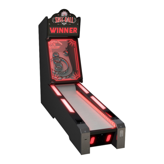
TABLE OF CONTENTS FACTORY CONTACT INFORMATION ……………………………….. TABLE OF CONTENTS ……………………….……………………….. WELCOME TO SKEEBALL GLOW ……….………………………….. GAME SPECIFICATIONS …………….……………………………….. SAFETY PRECAUTIONS …………….……………………………….. GAME SET UP ………………………………………………...…….. AVAILABLE OPTIONS TO LINK GAMES ……………..…………….. 9 BAYTEK GO APP ……………………………………….……….… 9-11 CARD SWIPE INSTALLATION ………………………….…………….. 12 HOW TO SET COIN COMPARITOR MECHS …….…………………... - Page 4 WELCOME TO SKEE-BALL Congratulations on your Skee-Ball purchase! Skee-Ball has been entertaining audiences at boardwalks, fairs and entertainment centers for over 110 years. Please take a moment to read through this manual as it contains a lot of helpful information. Be sure to contact our factory if you have any questions, or would like more information.
-
Page 5: Game Specifications
GAME SPECIFICATIONS WEIGHT POWER REQUIREMENTS NET WEIGHT 645 lbs 293 kg INPUT VOLTAGE 100 to 120 220 to 240 SHIP WEIGHT 695 lbs 318 kg RANGE INPUT FREQUENCY SHIPPING DIMENSIONS (1 Pallet) 60 Hz 50/60 Hz RANGE 80" x 32" x 92" at 695 lbs (Class 125) MAX OPERATING CURRENT GAME DIMENSIONS 2 AMPS @ 110 VAC / 1.3 AMP @ 220VAC... - Page 6 SKEEBALL GLOW SET UP The game will arrive on 1 pallet. Dimensions of pallet is 80” long by 32” wide by 92” tall. Please inspect the pallet for shipping damage and report immediately to the freight company if any damage is found. There will be about 1/2 hour of assembly time needed.
- Page 7 SKEEBALL GLOW SET UP Begin plugging the connectors from the ramp into the appropriate connectors from the target section. The green ground wire is located inside the target section. There are 2 of the red, white, and black 3 pin connectors. It does not matter how these plugs are connected.
- Page 8 SKEEBALL GLOW SET UP Install Top Marquee: The top marquee is lowered and reversed for shipping. This will now be removed and installed. Remove the hardware kit from the box with the balls. Remove the screws securing marquee for shipping using a Phil- lips screwdriver.
-
Page 9: Available Options To Link Games
AVAILABLE OPTIONS TO LINK GAMES The games can be linked with an Overhead Sign Part # AASIGN-SBG Linking features: Adjustable jackpot ticket increment per game. • Adjustable jackpot ticket win. • Synchronizes scrolling of displays during attract • mode. Auto selects alley color lighting so each alley is •... - Page 10 BAYTEK GO APP Expand the menus to view current message settings. Turn messages on or off by hitting the red buttons. You can add up to 5 custom messages by clicking the + message tab at the bottom of the screen. Edit messages and select the display color.
- Page 11 BAYTEK GO APP “Over-Scroll” is an option which the selected message will override the game’s display. (Including during game play) Messages can then be shown even in a busy game room. Press the “Override Scroll” tab to open the “Over Scroll Menu” Select how often the messages will scroll on the game’s displays.
-
Page 12: Card Swipe Installation
CARD SWIPE INSTALLATION The Skee Ball game is pre-wired with a UCL (Universal Card Link) connector to accept Card Swipe systems from many different manufactures. Please follow these instructions to make full use of this capability. This would normally plug into coin mechanism. -
Page 13: How To Set Coin Comparitor Mechs
HOW TO SET COIN COMPARITOR MECHS Coin comparators come standard on a Skee Ball game that is not specifically ordered for use with a card swipe system. These mechs are specifically designed to work with any size coin or token. Coin mechs can be swapped between games to identify a faulty mech. -
Page 14: Game Play Theory Of Operation
GAME PLAY THEORY OF OPERATION The game is designed to give points for balls scored through the target playfield. The Playfield Sensor under each hole will score the points, and will flash the light strip surrounding the score hole. Balls not reaching the target playfield will return to the ball track and the Ball Count Sensor will register them as zero points. -
Page 15: How To Access Menu Buttons & I/O Aux Board
HOW TO ACCESS MENU BUTTONS & I/O AUX BOARD Unlock the lock in the bottom, middle door below the ramp. Menu buttons, Speaker, and I/O Aux Board can now be accessed. HOW TO ACCESS MOTHERBOARD AND POWER SUPPLY Unlock the 2 locks in the marquee on the top of game. Tilt the marquee down. -
Page 16: Main Menu Functions
MAIN MENU FUNCTIONS The Menu and Menu Select buttons are located inside the lower alley front door. Press the “Menu Select” button during attract mode to dispense balls. This is useful to balance the amount of balls in each alley. Hold the MENU button down for 1 second to open the main menu on the display. - Page 17 GAME MENU Scroll through the menu with the “MENU” button. Make your selection with the “SELECT” Button. Hold the “SELECT” button to scroll faster. Default settings are highlighted in yellow below. N1 - SOFTWARE VERSION SKEEBALL - 1.1.7 Shows the software version of the game. Feb 5 2020 09: 05 : 52 N2 - SET CREDITS Sets the amount of coin pulses needed to start a game.
- Page 18 GAME MENU Scroll through the menu with the “MENU” button. Make your selection with the “SELECT” Button. Hold the “SELECT” button to scroll faster. Default settings are highlighted in yellow below. N7 - BALLS PER GAME Sets the amount of balls to be played per game. N8 - BALL TIMEOUT Sets the time the game will wait before going to “Game Over”...
- Page 19 GAME MENU The following menu options (N12-N27) are available if dipswitch # 4 is OFF Scroll through the menu with the “MENU” button. Make your selection with the “SELECT” Button. Hold the “SELECT” button to scroll faster. Default settings are highlighted in yellow below. N12 - EXTRA LAST BALL 10 Sec 20 Sec...
- Page 20 GAME MENU Scroll through the menu with the “MENU” button. Make your selection with the “SELECT” Button. Hold the “SELECT” button to scroll faster. Default settings are highlighted in yellow below. N18 - GAME STATISTICS Reports: The total number of games. Average score of these games.
- Page 21 GAME MENU Scroll through the menu with the “MENU” button. Make your selection with the “SELECT” Button. Hold the “SELECT” button to scroll faster. Default settings are highlighted in yellow below. N23 - GAME MODE TICKETS POINTS / AMUSEMENT ONLY PRIZES COUPONS Tickets - Will show tickets won on screen, and dispense tickets.
- Page 22 SIGN MENU The following menu options (N28-N36) are available if dipswitch #4 is OFF An overhead sign is attached and only accessible from the right hand game. Scroll through the menu with the “MENU” button. Make your selection with the “SELECT” Button. Hold the “SELECT”...
- Page 23 SIGN MENU Scroll through the menu with the “MENU” button. Make your selection with the “SELECT” Button. Hold the “SELECT” button to scroll faster. Default settings are highlighted in yellow below. N33 - SIGN ATTRACT TIMER Sets the amount of time that the sign celebration will remain on when the Bonus Score is reached. N34 - CELEBRATION TIMER 1m 30s Sets the amount of time that the sign celebration will remain on when the Bonus Score is reached.
-
Page 24: I/O Aux Board Dipswitch Settings
I/O AUX BOARD DIPSWITCH SETTINGS DESCRIPTION SWITCH SHOW GAME Set to ON to not dispense tickets and clears all accumulated credits AMUSEMENT ONLY Set to ON to not dispense tickets NJ LOCKOUT Set to ON to save tickets owed and unused credits after a power loss 1/2 TICKET PAYOUT Dispenses 1/2 the amount of tickets as shown on screen, rounding up odd amounts. -
Page 25: Motherboard Dipswitch Settings
MOTHERBOARD DIPSWITCH SETTINGS All dipswitches on the Motherboard are normally set to OFF DESCRIPTION ON OFF AAMB18000-SBG Motherboard Red Lane Lights Set to OFF to have RED lane covers and front plexi lights Blue Lane Lights Set to ON to have BLUE lane covers and front plexi lights Not Used Home Use Game... -
Page 26: Error Codes
ERROR CODES ROLL BALLS MESSAGE The game thinks there are balls in the ball track waiting to be rolled. This will disable the motor from releasing more balls. Remove right side lane cover and check the overflow sensor in ball track. -
Page 27: Circuit Board Pinouts
ALLEY CIRCUIT BOARD OVERVIEW AACE180012 AACE18010 Speaker 12 VDC to Coin Door AACE18003 Power to Motherboard AACE18045 AAMB18000-SBG 5VDC to AACE18000 Ramp Lights Display Motherboard Used AACE18045 AACE18041 5VDC to Playfield Shield LEDs Ramp Lights AACE18006 Ball track AACE18042 A5CB5156B sensors, Ramp LEDs AACE18004... -
Page 28: Wiring Diagrams
TICKET DISPENSER, COIN MECH, COUNTERS, AND MENU BUTTONS AACM-AS-COMP Coin Mechanism The AACM-AS-COMP coin mechanism will come with a cable. 2 Options: AACE1527-P To 12 Volt DC Large Connector Bill Acceptor A5AC9101 (AE2454 U5E) AACE18014 AACE1527 Small Connector AACE18009 AACE18014 12 VDC AACE18008 AACE18005... - Page 29 COMMUNICATION, PLAYFIELD AND RAMP LIGHTS A5CB5156B AAMB18000-SBG Power Dist. Board Motherboard AACE18012 Speaker from motherboard AACE18004 AACE18006 5 &12VDC Power to I/O Board AACE18004 Com to AACE18010 Motherboard Back of Game Front of Game Ball Count Sensor AACB3850A AACE18009 12VDC Coin Door Power Green LED on sensor is normally AACE18013...
- Page 30 ALLEY LED LIGHTS & BANG SENSOR A5CB5156B AAMB18000-SBG Power Dist. Motherboard Board AACE18041 AACE18050 Front Window LED’s AACE18045 AACE18042 AACE18045 5 VDC Power 5 VDC Power to Ramp Lights to Ramp Lights AACE18038 AACE18038 AACE18036 Back of Game Housings are colored RED Front of Game AACE18081...
- Page 31 AC POWER & POWER SUPPLY WIRING AACE18010 AACE18045 12 VDC to 5VDC to Coin Door Ramp Lights A5SW18000 AACE18045 On/Off Rocker 5VDC to Switch on the top Ramp Lights of game AAMB18000-SBG Motherboard AACE18003 5 &12VDC Power to Motherboard A5CB5156B Power Dist.
- Page 32 DISPLAY WIRING AAMB18000-SBG Motherboard AACE18003 A5CB5156B 5 &12VDC Power Dist. Power to Board Motherboard AACE18000 AACE18011 5 VDC Power to Display AACE18033 12 VDC Power to LED lights 5 VDC Power AACE18000 to Display in Marquee AACE18002 AACE18001 A5LD1052 A5LD1052 A5CE9736 Display Display...
- Page 33 PLAYFIELD SENSOR WIRING DIAGRAM CE18025 CE18024 CE18023 CE18022 CE18021 CE18020 CE18019 Cables plugged across top of motherboard correspond to score sensors. AAMB18000-SBG Motherboard AACE18032 AACB3851A-B AACB3851A-B AACE18054 AACB3851A-B AACE18052 AACE18053 Cables continue on AACE18052 pass-thru AACE18052 board to the motherboard AACB3851A-B CE18025 AACE18052...
-
Page 34: Troubleshooting Guide
Troubleshooting Guide TROUBLESHOOTING GUIDE Problem Probable Cause Remedy Unplugged. Check wall outlet to line filter in back of game. (A5FI9011) Faulty Line Filter Replace Line Filter. (A5FI9011) No power to the Faulty Cable Refer to wiring diagram. Check cables CE18035, CE18034 game Rocker Switch on top Check rocker switch on top of game. - Page 35 TROUBLESHOOTING GUIDE Problem Probable Cause Remedy Faulty Cable Check cables from LED strips to Power Distribution Board (CE18083, CE18033) LED marquee Verify 12 Volts DC from Check for 12 volts DC on CE18033 on Power Distribution lighting not Power Distribution Board working Board LED strip faulty...
- Page 36 TROUBLESHOOTING GUIDE Problem Probable Cause Remedy Pinched, broken, or Refer to wiring diagram. Ensure 5 volts DC on CE18011, Display not disconnected wiring. CE18002 & CE18001 cables from power distribution board. working Check communication ribbon cable from Motherboard to Display Boards.
- Page 37 TROUBLESHOOTING GUIDE Problem Probable Cause Remedy Game also does not Check communication cable from Motherboard to I/O Aux Board. Menu Buttons coin up? CE18004, CE18005. Check Molex connector at the rear of the not working ramp. Ensure power to I/O Aux Board. Pinched, broken, or Refer to wiring diagram.
- Page 38 TROUBLESHOOTING GUIDE Problem Probable Cause Remedy Lane matting or Matting will get dirty with Clean with “Scrubbing Bubbles” brand cleaner. target area is use. dirty Too many balls in the ball Open the middle lower door to access Green Dot on track.
-
Page 39: Power Supply Diagnostics
POWER SUPPLY DIAGNOSTICS 1.) Verify AC power to game. Check the rocker switch on top of the cabinet. 2.) Check power in connection to power supply. 3.) Ensure Power Supply switch is set to 115V (or 230V) (Some model power supplies may not have this) 4.) Ensure Power switch is on. -
Page 40: How To Access Target Sensors
HOW TO ACCESS TARGET SENSORS Remove the 4 bolts (A5SCBH027) from the front plexi using a 5/32” Allen Wrench. Lower front plexi slightly and unplug the square Molex connector and then remove front plexi from cabinet. Remove the 2 screws in the left and right rubber ends using a Phillips screwdriver Pivot and pull the playfield to the left to access the cables on the lower left corner. -
Page 41: How To Change Ball Release Motor
HOW TO CHANGE BALL RELEASE MOTOR Unlock the lock on the right lane cover of the alley using a H95 Key. Slide lane cover up and remove from alley. Remove the balls in the track. Slide up both wood blocks holding the sensors. Unplug the connectors, and remove the sensors from the cabinet. - Page 42 HOW TO CHANGE BALL RELEASE MOTOR Pivot motor/bracket and lift upward out of channel. Remove 4 bolts using 5/16” wrench to re- move old motor from bracket. Unplug motor power from the yellow & black wire connector. Install new motor onto bracket, plug new motor into yellow &...
-
Page 43: How To Update Software
HOW TO UPDATE SOFTWARE The motherboard software can be easily updated with a USB flash drive stick. Instructions: AAMB3852-SBG Copy the program file onto a blank USB thumb drive stick. Motherboard Make sure the game is turned ON. Insert the USB thumb drive into the slot on the motherboard assembly. -
Page 44: Playfield Parts
PLAYFIELD PARTS AATA18000-10000R A5DE18006 10000 Point Target AABU8701 Backboard Decal Right Ring Anti-ball Jam Obstacle (Set of 2) AABU8101 AATA18000-10000L Bumper for 100/10000 10000 Point Target Score Rings Left Ring AATA18000-5000 5000 Point Target Ring AABA8100 Small Sand Bag AATA18000-4000 4000 Point Target Ring AABA8101 Medium Sand Bag... -
Page 45: Parts List
PARTS LIST PART # DESCRIPTION PART # DESCRIPTION A5BA5810 Blue Ball (9 Per Game) AABK1013 Push Buttons/Counter Bracket W/Decal AACM-AS-COMP Coin Comparator with Cable A5ME8123 Metal Rear Carpet Clamp W5TM4000 7/8" Black T-Molding (18 feet per game) A5ME8714 Metal Plate for Obstacle Bumpers (2/game) A5FO8103 Foam Black Neoprene Set A5ME15005... - Page 46 PARTS LIST AACE18029 Playfield Sensor #4 From Playfield Cable A5DE18009 Plexi Light Covers on holes (4") (4 per game) AACE18030 Playfield Sensor #5 From Playfield Cable A5DE18010 Plexi Light Covers on holes (7 1/4") (2 per game) AACE18031 Playfield Sensor #6 From Playfield Cable A5DE18011 Window Cling Decal AACE18032...
-
Page 47: Parts Pictures
PARTS PICTURES A5BA5810 AACM-AS-COMP W5TM4000 A5FO8103 A5PL8600 A5CL3401 A5PIRO015 A5PICV015 A5SCBH027 A5WR3800 A5FC0080 AASW200 A5SW18000 A5LK2001 A5LK5002 A5HA3850 A5KIT-SBG22 A5BU8100 AABU8100 AABU8101 AABU8701 A5BA17000 AABA17001 AABA17002 AABA8100-SET A5LA3850 A5LA3851 A5CA2102 A5ME5150 AAME17016 A5BK6035 A5BK9999 AABK1013 A5ME8123 A5ME8714 A5ME15005 A5ME17011 A5ME17012 A5ME17013 A5ME17014 A5ME17015... - Page 48 PARTS PICTURES AACE18008 AACE18009 AACE18010 AACE18011 AACE18012 AACE18013 AACE18014 AACE18015 AACE18016 AACE18017 AACE18018 AACE18019 AACE18020 AACE18021 AACE18022 AACE18023 AACE18024 AACE18025 AACE18026 AACE18027 AACE18028 AACE18029 AACE18030 AACE18031 AACE18032 AACE18033 AACE18034 AACE18035 AACE18036 AACE18037 AACE18038 AACE18039 AACE18040 AACE18041 AACE18042 AACE18043 AACE18044 AACE18045 AACE18046 AACE18048 AACE18049...
- Page 49 PARTS PICTURES A5DE18009 A5DE18010 A5DE18011 A5DE18013 A5DE18014 A5LD1052 A5FI9011 AACO1020 AACE8811A A5TD1 A5PS1021 AACB3850A AACB3851A-B A5CB5156 AACB15001 AACB18001 AACB9605A-SBG AAMB18000-SBG...
-
Page 50: Maintenance Log
REPAIR/MAINTENANCE LOG If you need to make repairs or order replacement parts it is a good idea to keep a log. Below is a chart you can use to track repairs and maintenance. DATE MAINTENANCE PERFORMED PARTS ORDERED MISC. NOTES... -
Page 51: Technical Support
TECHNICAL SUPPORT Excellent customer service is very important to Bay Tek Entertainment! We know that keeping your games in great operating condition is important to your business. When you need us, we are here to help. You can call us for free technical assistance, and you can count on us to have parts on-hand to support your game. -
Page 52: Skeeball Glow Overhead Sign Supplement
SIGN MANUAL SUPPLEMENT... - Page 53 SKEEBALL GLOW OVERHEAD SIGN AACE18068 AACE18057 Ribbon Cable AACE18060 Bell to Display 12 VDC to top lights AAMB18000-SBG-SIGN A5CB5156B Power Dist. Motherboard Board AACE18073 Interface Bd Com AACE18062 5 VDC to AACE18065 Display Bluetooth Cable AACE18067 5 &12VDC Power to Motherboard AACE18060 Comm to top...
- Page 54 SKEEBALL GLOW OVERHEAD SIGN A5LD18001 A5LD18001 Sign has 9 identical A5CB10002 light spires. A5CB10002 A5LD18001 This wiring is duplicated on all 9 A5CE18000 spires. A5CE18000 A5CB10002 A5CB10002 A5CE18000 A5CB10002 AALB18058 A5CB5156B Power Dist. Board 12 VDC AACE18060 AAMB18000-SBG-SIGN Motherboard AACE18067 5 &12VDC Power to Motherboard...
- Page 55 LINKING GAMES, BLUETOOTH & BELL AABE18000 AACE18057 Bell 4.8 MOhm AACB3853A Bluetooth Board AAMB18000-SBG-SIGN AACE18065 Bluetooth Cable Motherboard AACE18073 Interface Bd Com This end only used in case of linking more AACE18063 than 8 games AACE1806 Interface Bd Cable AACE18063 Interface Bd Cable Used AACB2205-D...
- Page 56 POWER IN AACE18060 12 VDC to Light Spires A5CB5156B Power Dist. Board AACE18062 5 VDC Power to Display AACE18067 Power 5 &12VDC Supply Power to Voltage Motherboard AAMB18000-SBG-SIGN Motherboard AACE18061 12 VDC to LED A5PS1021 Power Supply A5SW18000 On/Off Rocker Switch on the side of the sign AACE18072...
- Page 57 TROUBLESHOOTING GUIDE Troubleshooting Guide Problem Probable Cause Remedy Unplugged. Check wall outlet to line filter in back of sign. (A5FI9011 Faulty Line Filter Replace Line Filter. (A5FI9011 No power to the Faulty Cable Refer to wiring diagram. Check cable CE18072 sign Rocker Switch onside Check rocker switch on side of sign.
- Page 58 TROUBLESHOOTING GUIDE Problem Probable Cause Remedy Loose connection Check cable connections at Bluetooth Board and at motherboard. Ensure the phone cable is plugged into the top socket on the motherboard. Bluetooth not Does the phone If not - replace the Bluetooth Board. Part # AACB3853A communicating “See”...
- Page 59 HOW TO LINK GAMES AAMB18000-SBG-SIGN Motherboard Important: If games do not appear to link, go into the menu of all lower connect alley games and do a “Restore Factory Settings” (N36) AACE18073 Interface Bd Com This end only used in case of linking more than 8 games AACE1806...
Need help?
Do you have a question about the Skee-Ball Glow 22 and is the answer not in the manual?
Questions and answers