Table of Contents
Advertisement
Advertisement
Table of Contents

Related Manuals for Bay-Tek Skee Ball


Summary of Contents for Bay-Tek Skee Ball
-
Page 2: Factory Contact Information
FACTORY CONTACT INFORMATION BAY TEK GAMES INC. Pulaski Industrial Park 1077 East. Glenbrook Drive Pulaski, WI 54162 USA JOIN OUR SERVICE FIRST NETWORK! This free service is intended to keep you up to date on the latest game information, early notification of parts specials, pertinent technical bulle- tins, updates on retro fit parts, software upgrades, and much more. -
Page 3: Welcome To: Skee Ball Classic
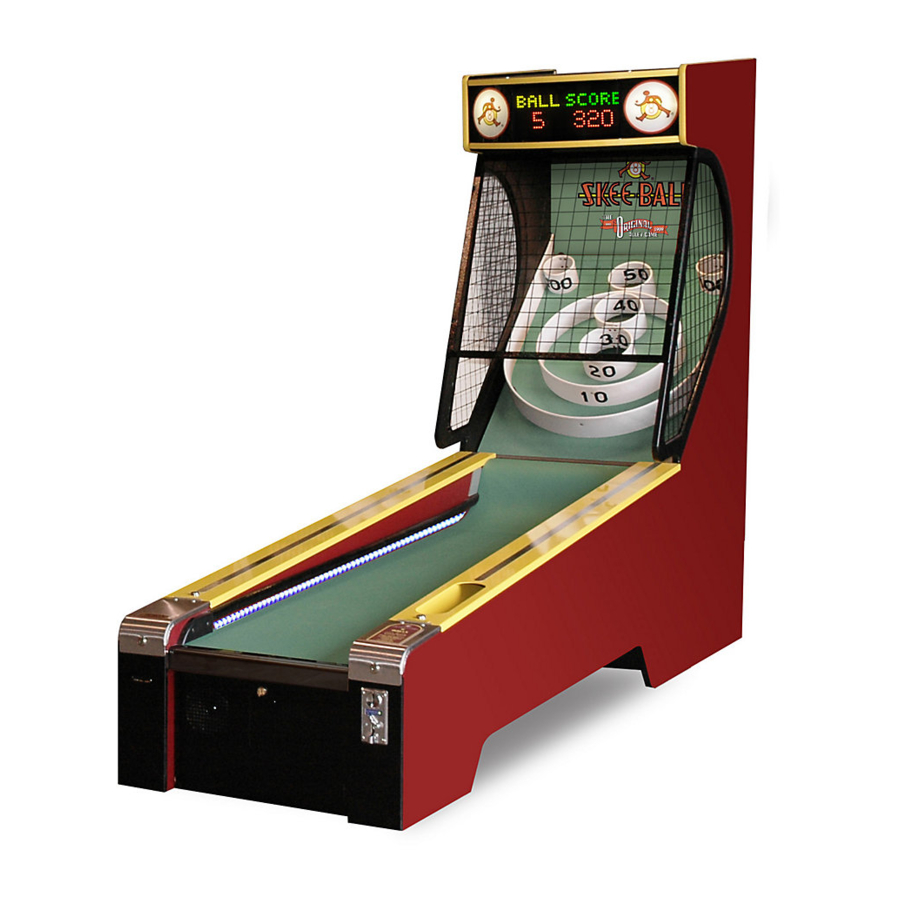
WELCOME TO: Skee Ball Classic Congratulations on your Skee Ball Classic purchase! This original alley is a staple for any venue and is a proven revenue producer! The Classic game entices players to play game after game, improving their skill and is... -
Page 4: Table Of Contents
WELCOME TO: Skee Ball Classic ........ - Page 5 TABLE OF CONTENTS TICKET MINIMUM ........... . 25 TICKET MAXIMUM .
-
Page 6: Warnings
WARNINGS Read this manual thoroughly before assembling your game. Failure to follow the instructions could cause damage to your game and void your warranty. In addition, the manual explains the game in detail and the options you have so that you and your players can enjoy the game to its fullest. A. -
Page 7: Assembly Instructions
ASSEMBLY INSTRUCTIONS PRE-ASSEMBLY Remove all parts from the shipping boxes and inspect for any possible damage during handling. Use the list on the specifications page to inventory the items. If any part(s) are missing, call your salesperson immediately. If shipping damage is noted, call the trucking company making the delivery. - Page 8 2. Move alley nearly into position and connect cables. 3. Move alley tight against back cabinet and fasten using the 5/16” allen wrench provided.
- Page 9 4. Connect the linking cables. Insert cable into one of the two ‘phone jacks’ . On two side-by-side games, to create a ‘daisy chain’ . Routing cable through the large holes in the rear of the electronics area or the Alley. If a Jackpot Sign is being used, connect it to the game on one end. 5.
-
Page 10: Functional Description
FUNCTIONAL DESCRIPTION MAJOR GAME COMPONENTS BACK CABINET ASSEMBLY: This portion of the game houses the score display panel and target board assembly. RUNWAY ASSEMBLY (ALLEY): This assembly houses the ball release assembly, coin mech., ticket dispenser, ball count sensor, ball release sensor, ticket counter, coin counter and prog/aux switches and all control electronics. -
Page 11: Scoreboard Display Cover
SCOREBOARD DISPLAY COVER: Located in front of the score panel. It is easily removable by bowing slightly and pulling on the knob at the top center to gain access to the light bulbs, and display board. CONTROLLER ASSEMBLY: This assembly is located in the electronics area below the runway at the front of the game. The CPU is on one printed circuit board and is referred to as the Universal Controller (P/N: 632065-10), normally mounted on door. -
Page 12: Power Supply And Solenoid Relay
When DBA option is included, CPU is mounted on a plate on wall of electronics area to allow room for DBA. POWER SUPPLY AND SOLENOID RELAY: The power supply (P/N: 800758-1) and the solenoid relay (P/N: 801716-1) are located in the electronics area below the runway at the front of the game. -
Page 13: Opto-Sensors
OPTO-SENSORS: Used at all pockets on target board, they are Omron Opto-interrupters (P/N: 800773-3). They are located on a rail and two small brackets, on the underside of the target board. This part is also used for the ball count and ball release functions. SINGLE BALL RELEASE ASSEMBLY: Located on underside of the right side channel cover. -
Page 14: Ball Count Sensor
BALL COUNT SENSOR: Located in the right side ball return channel and mounted to the rear end of the alley right side Channel Cover. It counts balls that are played. The main function is to count balls that do not enter a pocket and it decides the game end when the total number of balls is returned. -
Page 15: Target Board Protective Net (Cages)
TARGET BOARD PROTECTIVE NET (CAGES): There are 3 different panels fabricated out of hard PVC frame and metal mesh. These are fastened to the back cabinet assembly to protect the Target Board from players trying to cheat by throwing balls directly into the targets and to reduce the possibility of the ball going astray. -
Page 16: Ticket Dispenser
TICKET DISPENSER: Located in the left front portion of the alley behind Ticket Door. This device dispenses tickets to the player. COIN MECH / CASH BOX Located in the right front portion of the alley inside the Coin Door. This unit collects coins/tokens and contains the cash box. -
Page 17: Program/Counter Pcb
DISPLAY: Located behind the display panel. This display is referred to as 14x45 Tricolor Display (P/N: 632084-1). This LED display shows the score, ball count, credits and all programmable options and settings. PROGRAM/COUNTER PCB: Located in the electronics area below the runway at the front of the game. Is used to programs all game options, and counts tickets and coins. -
Page 18: Dba (Optional)
DBA (OPTIONAL): An optional Dollar Bill Acceptor maybe located on the right side of the electronics area door. -
Page 19: Runway Led Option
RUNWAY LED OPTION Located under Banking Strips. They add extra light to the runway if this option has been added. BALANCE BUTTON Located under right front channel cover. Press to release balls to balance without coining up game. -
Page 20: Major Jackpot Sign Components
MAJOR JACKPOT SIGN COMPONENTS JACKPOT CONTROLLERASSEMBLY This assembly is located inside the Jackpot Sign, directly behind the display. It is attached to a plate mounted in the rear. The CPU is on one printed circuit board and is referred to as the Universal Controller (P/N: 632065-10). -
Page 21: Fluorescent Lights
FLUORESCENT LIGHTS: Three Fluorescent light fixtures are attached to the rear on the cabinet. ROPE LIGHT: Used to accent sign, two strands run around along the outside edge of the sign. -
Page 22: Programming Overview
PROGRAMMING OVERVIEW The programming mode is entered and exited by pushing the “RESET” button on the prog/counter pcb located on the inside of the electronics area, under the front of the alley, on the door. NOTE: PROGRAMMING INFORMATION WILL BE SHOWN ON THE DISPLAY PANEL OF THE GAME. To VIEW the various game options, use the AUX 1 button on the counter / control panel of the game. -
Page 23: Notes For Initial Link Set Up
NOTES FOR INITIAL LINK SET UP Link the games together as described in the game unit id section below. Once the games are linked together, all games will program together. From then on, setting one game will set them all. Any game can be used to program the games or jackpot sign. Games must be linked together with the supplied link cables to work together. -
Page 24: To Play (Money)
TO PLAY (MONEY): This option is used to set what the player sees when they walk up to the game as far as inserting money is concerned. Controls the wording of the messages, based on what you set. The options for this are as follows: COINS TOKENS... -
Page 25: Ticket Span Points
TICKET SPAN POINTS This option determines the intervals that tickets will be issued. For example, if the INITIAL TICKET THRESHOLD is set for 150 and the ticket span is set to 30, the first ticket is issued at 150 and the next one would be issued at 180, then 210, and every 30 points thereafter. The range for this option is NONE-300. -
Page 26: Extra Ball Quantity
EXTRA BALL QUANTITY If the EXTRA BALL option above is active, set this option to determine how many extra balls will be given. The range for this option is 1-10. The default value for this option is “3”. BONUS POCKET MULTIPLIER This option is used to DOUBLE the value of the 100 point bonus pocket to 200 for consecutive 100 point scores. -
Page 27: Lost / Unplayed Ball Timeout
LOST / UNPLAYED BALL TIMEOUT This option is used in case a ball is lost or not thrown soon enough. If a ball is not played within the allotted time, the ball counter will advance. The time (in seconds) for this option is 0-60. Setting a “0” turns this option off. -
Page 28: Jackpot Sign Payout
JACKPOT SIGN PAYOUT This option is used to determine HOW the SIGN TICKETS are paid out to the player. There are 3 different ways to dispense the SIGN Tickets. DISPENSE - In this mode, the tickets are dispensed as soon as the player wins the bonus. ALSO, additional games can be played while tickets are being dispensed from the game. -
Page 29: Game Play
GAME PLAY After the proper number of coins have been inserted, the controller turns the Ball Release Solenoid ON, and the proper number of balls are released. The following conditions should exist: a. Score is 000 b. Balls played is 0 c. - Page 30 TICKET DISPENSER CONTROLLER BOARD: Attached to the ticket machine is a transistor motor controller that provides dynamic braking to ensure accurate and repeatable ticket stopping after issuing any number of tickets. Included as part of the controller is ticket sensing by means of an opto beam breaker sensor. Also included is signal conditioning, which provides high electrical noise immunity.
-
Page 31: General Troubleshooting
GENERAL TROUBLESHOOTING CAUTION: High voltage is present in some areas of the alley (power supply, SCR, solenoid, etc.). Unplug line cord before performing any troubleshooting. PROBLEM RECOMMENDATION NO DISPLAY 1. Make sure power is applied to the alley. 2. Check the connections on the cable from the controller to the display. -
Page 32: Maintenance Notes
MAINTENANCE NOTES: WHEN REMOVING CHANNEL COVERS, DO NOT LEAVE KEY IN LOCK BECAUSE IT WILL DAMAGE THE RUNWAY CARPET. WHEN REINSTALLING CHANNEL COVERS SLIDE TABS ON REAR OF COVER INTO SLOTS IN THE ALLEY TO SECURE. -
Page 33: Parts List
PARTS LIST: PART NUMBER DESCRIPTION 212099-1 ART SET,SKEEBALL 2010 212099-2 ART,MARQUEE PANEL 212099-3 ART,TICKET DECAL,SKEEBALL 2010 386096-13 ASSY,BALLAST,DUAL BULB,JACKPOT 212018-1 ASSY,BRACKET,LOCK MTG 212024-1 ASSY,CAGE,LEFT SIDE 212025-1 ASSY,CAGE,RIGHT SIDE 212138-1 ASSY,DOOR,FRONT CTR,WO/DBA 212141-1 ASSY,LOCK MOUNTING,RUNWAY 212023-1 ASSY,MARQUEE FRONT COVER 212123-1 ASSY,TICKET BIN 800179-52 BALL, SKEE 3-1/8”...
Need help?
Do you have a question about the Skee Ball and is the answer not in the manual?
Questions and answers